Transcription
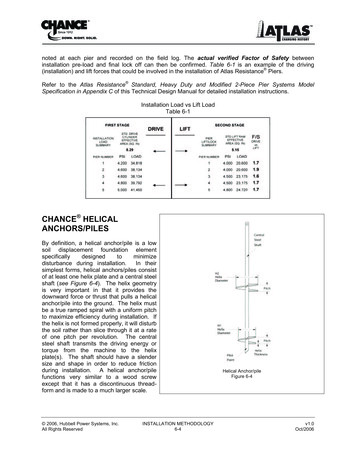
noted at each pier and recorded on the field log. The actual verified Factor of Safety betweeninstallation pre-load and final lock off can then be confirmed. Table 6-1 is an example of the driving(installation) and lift forces that could be involved in the installation of Atlas Resistance Piers.Refer to the Atlas Resistance Standard, Heavy Duty and Modified 2-Piece Pier Systems ModelSpecification in Appendix C of this Technical Design Manual for detailed installation instructions.Installation Load vs Lift LoadTable 6-1CHANCE HELICALANCHORS/PILESBy definition, a helical anchor/pile is a lowsoil displacement foundation elementspecificallydesignedtominimizedisturbance during installation.In theirsimplest forms, helical anchors/piles consistof at least one helix plate and a central steelshaft (see Figure 6-4). The helix geometryis very important in that it provides thedownward force or thrust that pulls a helicalanchor/pile into the ground. The helix mustbe a true ramped spiral with a uniform pitchto maximize efficiency during installation. Ifthe helix is not formed properly, it will disturbthe soil rather than slice through it at a rateof one pitch per revolution. The centralsteel shaft transmits the driving energy ortorque from the machine to the helixplate(s). The shaft should have a slendersize and shape in order to reduce frictionduring installation. A helical anchor/pilefunctions very similar to a wood screwexcept that it has a discontinuous threadform and is made to a much larger scale. 2006, Hubbell Power Systems, Inc.All Rights ReservedINSTALLATION METHODOLOGY6-4Helical Anchor/pileFigure 6-4v1.0Oct/2006
INSTALLATION TORQUE/LOAD CAPACITY RELATIONSHIPBefore installation, a helical anchor/pile is simply a screw with a discontinuous thread and a uniform pitch.When installed into soil, a helical anchor/pile functions as an axially loaded end-bearing deep foundation.The helix plates serve a two-fold purpose. The first purpose is to provide the means to install the helicalanchor/pile. The second purpose is to provide the bearing element means for load transfer to soil. Assuch, helical anchor/pile design is keyed to these two purposes, both of which can be used to predict theultimate capacity.Section 5 detailed how helix plates act as bearing elements. The load capacity is determined bymultiplying the unit bearing capacity of the soil at each helix location by the projected area of each helix.This capacity is generally defined as the ultimate theoretical load capacity because it is based on soilparameters either directly measured or empirically derived from sounding data.This intent of this section is to provide a basic understanding of how installation torque (or installationenergy) provides a simple, reliable means to predict the load capacity of a helical anchor/pile . Moreimportantly, this prediction method is independent of the bearing capacity method detailed in Section 5,so it can be used as a “field production control” method to verify load capacity during installation.The installation torque-to-load capacity relationship is an empirical method originally developed by the A.B. Chance Company. CHANCE Civil Construction has long promoted the idea that the torsion energyrequired to install a helical anchor/pile can be related to the ultimate load capacity of an anchor/pile.Precise definition of the relationship for all possible variables remains to be achieved. However, simpleempirical relationships have been used for a number of years. The principle is that as a helicalanchor/pile is installed (screwed) into increasingly denser/harder soil, the resistance to installation (calledinstallation energy or torque) will increase. Likewise, the higher the installation torque, the higher theaxial capacity of the installed anchor/pile. Hoyt and Clemence (1989) presented a landmark paper on thistopic at the 12th International Conference on Soil Mechanics and Foundation Engineering. Theyproposed the following formula that relates the ultimate capacity of a helical anchor/pile to it's' installationtorque:where:Qult Kt x T(Equation 6-1)QultKtT Ultimate uplift capacity [lb (kN)]Empirical torque factor [ft-1 (m-1)]Average installation torque [lb-ft (kN-m)]Hoyt and Clemence recommended Kt 10 ft-1 (33 m-1) for square shaft (SS) and round shaft (RS) helicalanchors/piles less than 3.5" (89 mm) in diameter, 7 ft-1 (23 m-1) for 3.5" diameter round shafts, and 3 ft-1(9.8 m-1) for 8-5/8" (219 mm) diameter round shafts. The value of Kt is not a constant - it may range from3 to 20 ft-1 (10 to 66 m-1), depending on soil conditions, shaft size and shape, helix thickness, andapplication (tension or compression). For Chance Type SS square shaft helical anchors/piles, Kttypically ranges from 10 to 12 ft-1 (33 to 39 m-1), with 10 ft-1 (33 m-1) being the recommended defaultvalue. For Chance Type RS pipe shaft helical anchors/piles, Kt typically ranges from 6 to 10 ft-1 (20 to33 m-1), with 8 ft-1 (26 m-1) being the recommended default for Type RS2875; 7 ft-1 (23 m-1) being therecommended default for Type RS3500.300; and 6 ft-1 (20 m-1) being the recommended default for TypeRS4500.337.Locating helix bearing plates in very soft, loose, or sensitive soils will typically result in Kt values less thanthe recommended default. This is because some soils, such as salt leached marine clays and lacustrineclays, are very sensitive and lose considerable shear strength when disturbed. It is better to extend thehelical anchor/pile beyond sensitive soils into competent bearing strata. If it’s not practical to extend thehelical anchor/pile beyond sensitive soils, testing is required to determine the appropriate Kt. 2006, Hubbell Power Systems, Inc.All Rights ReservedINSTALLATION METHODOLOGY6-5v1.0Oct/2006
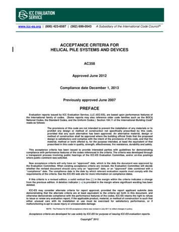
Top View of HelixFigure 6-5Full-scale load testing has shown that helical anchors/pilestypically have at least the same capacity in compression asin tension. In practice, compression capacity is generallyhigher than tension capacity because the anchor/pile bearson soil below rather than above the helix plates, plus atleast one helix plate is bearing on undisturbed soil. Soilabove the bearing plates is slightly disturbed by the slicingaction of the helix, but not overly disturbed by being“augured” and removed. Typically, the same values of Ktare used for both tension and compression applications.This generally results in conservative results forcompression applications. A poorly formed helix shape willdisturb soil enough to adversely affect the torque-tocapacity relationship, i.e., Kt is reduced. To prevent this,CHANCE Civil Construction uses matching metal dies toform helix plates which are as near to a true helical shapeas is practically possible. To understand all the factors thatKt is a function of, one must first understand how helicalanchors/piles interact with the soil during installation.Torque FactorsThere are two main factors that contribute to the torqueresistance generated during an anchor/pile installation,friction and penetration resistance. Of the two factors,friction is by far the larger component of torque resistance.Friction Has Two Basic Parts:(1) Friction on the helix plate and friction along the centralsteel shaft. Friction resistance increases with helix sizebecause the surface area of the helix in contact with the soilincreases with the square of the diameter (see Figure 6-5).Likewise, friction resistance increases with pitch size, i.e.,the larger the pitch, the greater the resistance. This isanalogous to the difference between a coarse thread and afine thread bolt. Basic physics tells us that “work” is definedas force times distance. A larger pitch causes the helix totravel a greater distance per revolution, thus more work isrequired.Friction Forces Action on Central ShaftsFigure 6-6 2006, Hubbell Power Systems, Inc.All Rights Reserved(2) Friction along the central steel shaft is similar to frictionon the helix plate. Friction resistance increases with shaftsize because the surface area of the shaft in contact withthe soil increases as the diameter increases. An importantperformance factor for helical anchors/piles is the helix toshaft diameter ratio (Hd/Sd). The higher the Hd/Sd ratio, themore efficient a given helical anchor/pile will be duringinstallation. Friction resistance also varies with shaft shape(see Figure 6-6). A round shaft may be the most efficientsection to transmit torque energy, but it has thedisadvantage of full surface contact with the soil duringINSTALLATION METHODOLOGY6-6v1.0Oct/2006
installation. When the central steel shaft is large ( 3" [76mm] in diameter) the shaft friction resistance contributessignificantly to the total friction resistance. However, asquare shaft has only the corners in full surface contact withthe soil during installation, thus less shaft friction resistance.Friction energy (energy loss) required to install a helicalanchor/pile is related to the helix and shaft size. The totalenergy loss due to friction is equal to the sum of the frictionloss of all the individual helix plates plus the length of shaftsubjected to friction via contact with the soil.Penetration Resistance Has Two Basic Parts:Section View of LeadingEdge with Flow LinesFigure 6-7(1) Shearing resistance along the leading edge of thehelix plate and penetration resistance of the hub pilotpoint. Shearing resistance increases with helix sizebecause leading edge length increases as the diameterincreases. Shearing resistance also increases with helixthickness because more soil has to be displaced with athick helix than with a thin helix (see Figure 6-7). Theaverage distance the soil is displaced is equal toapproximately 1/2 the helix thickness, so as the thicknessincreases the more work (i.e., energy) is required to passthe helix through the soil.(2) Penetration resistance increases with shaft sizebecause the projected area of the hub/pilot pointincreases with the square of the shaft radius (see Figure6-8). The average distance the soil is displaced isapproximately equal to the radius of the shaft, so as theshaft size increases, the more work (i.e., energy) isrequired to pass the hub/pilot point through the soil.The penetration energy required to install a helicalanchor/pile is proportional to the volume of soil displacedtimes the distance traveled. The volume of soil displacedby the anchor/pile is equal to the sum of the volumes ofall the individual helix plates plus the volume of the soildisplaced by the hub/pilot point in moving downward withevery revolution.Hub/Pilot Point with Flow LinesFigure 6-8 2006, Hubbell Power Systems, Inc.All Rights ReservedINSTALLATION METHODOLOGY6-7v1.0Oct/2006
Energy RelationshipsInstallation energy must equal the energy required to penetrate the soil (penetration resistance) plus theenergy loss due to friction (friction resistance). The installation energy is provided by the machine andconsists of two components, rotation energy supplied by the torque motor and downward force (or crowd)provided by the machine. The rotation energy provided by the motor along with the inclined plane of atrue helical form generates the thrust necessary to overcome the penetration and friction resistance. Therotational energy is what is termed “installation torque.” The downward force also overcomes penetrationresistance, but its contribution is usually required only at the start of the installation, or when the lead helixis transitioning from a soft soil to a hard soil.From an installation energy standpoint, the perfect helical anchor/pile would consist of an infinitely thinhelix plate attached to an infinitely strong, infinitely small diameter central steel shaft. This configurationwould be energy efficient because penetration resistance and friction resistance is low. Installation torqueto capacity relationships would be high. However, infinitely thin helix plates and infinitely small shafts arenot realistically possible, so a balanced design of size, shape, and material is required to achieveconsistent, reliable torque to capacity relationships.As stated previously, the empirical relationship between installation torque and ultimate capacity is wellknown, but not precisely defined. As one method of explanation, a theoretical model based on energyexerted during installation has been proposed [Perko (2000)]. The energy model is based on equatingthe energy exerted during installation with the penetration and friction resistance. Perko showed how thecapacity of an installed helical anchor/pile can be expressed in terms of installation torque, applieddownward force, soil displacement, and the geometry of the anchor/pile. The model indicates that Kt isweakly dependent on crowd, final installation torque, number of helix plates, and helix pitch. The modelalso indicates that Kt is moderately affected by helix plate radius and strongly affected by shaft diameterand helix plate thickness.The important issue is energy efficiency. Note that a large shaft helical anchor/pile takes more energy toinstall into the soil than a small shaft anchor/pile. Likewise, a large diameter, thick helix takes moreenergy to install into the soil than a smaller diameter, thinner helix. The importance of energy efficiency isrealized when one considers that the additional energy required to install a large displacement helicalanchor/pile contributes little to the load capacity of the anchor/pile. In others words, the return on theenergy “investment” is not as good. This concept is what is meant when CHANCE Civil Constructionengineers say large shaft diameter and/or large helix diameter ( 16” diameter) anchors/piles are notefficient “torque-wise.”If one considers an energy balance between the energy exerted during loading and the appropriatepenetration energy of each of the helix plates, then it can be realized that any installation energy notspecifically related to helix penetration is wasted. This fact leads to several useful observations. For agiven helix configuration and the same available installation energy (i.e., machine):1. Small displacement shafts will disturb less soil than large displacement shafts.2. Small displacement shafts result in less pore pressure buildup than large displacement shafts.3. Small displacement shafts will penetrate farther into a given bearing strata than largedisplacement shafts.4. Small displacement shafts will penetrate soils with higher SPT “N” values than large displacementshafts.5. Small displacement shafts will generate more axial load capacity with less deflection than largedisplacement shafts.6. Kt varies inversely with shaft diameter. 2006, Hubbell Power Systems, Inc.All Rights ReservedINSTALLATION METHODOLOGY6-8v1.0Oct/2006
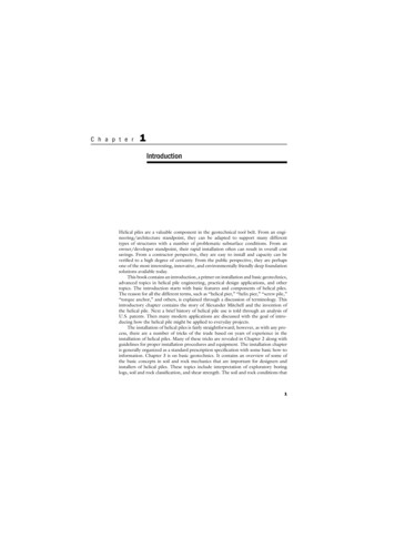
Reliability of Torque/Capacity ModelHoyt and Clemence (1989) analyzed 91load tests at 24 different sites with sand,silt and clay soils all represented. All of thetests used in the study were short term;most were strain controlled and included afinal loading step of imposing continuousdeflection at a rate of approximately 4inches (102 mm) per minute. This finalload was taken as the ultimate capacity.The capacity ratio Qact/Qcalc was obtainedfor each test by dividing the actual capacity(Qact) by the calculated capacity (Qcalc).Qcalc was calculated by using threedifferent load capacity models: (1)cylindrical shear, (2) individual bearing,and (3) torque correlation. These datawere then compared and plotted onseparate histograms (see Figures 6-9 and6-10, cylindrical shear histogram notshown).Individual Bearing MethodFigure 6-9Torque Correlation ModelFigure 6-10 2006, Hubbell Power Systems, Inc.All Rights ReservedAll three capacity models exhibited thecapability of over-predicting anchor/pilecapacity. This would suggest the use ofappropriate Factors of Safety. However, theauthors did not discriminate between “good”and “poor” bearing soils when analyzing theresults. In other words, some of the testdata analyzed was in areas where the helixplates were located in soils typically notsuitable for end bearing, (i.e., sensitive)clays and loose sands.All three capacity models’ mean values werequite close, but the range and standarddeviation were significantly lower for thetorque correlation method than for the othertwo. This improved consistency is probablydue to the removal of several randomvariables from the capacity model.Therefore, the installation torque correlationmethod yields more consistent results thaneither of the other two methods.Theinstallation torque method does have onedisadvantage, however, in that it cannot beused until after the helical anchor/pile hasbeen installed. Therefore, it is better suitedto on-site production control and terminationcriteria than design in the office.INSTALLATION METHODOLOGY6-9v1.0Oct/2006
Measuring Installation TorqueThe torque correlation method requires the installation torque to be measured and recorded in the field.There are several methods that can be used to measure torque, and CHANCE Civil Construction has acomplete line of torque indicators to choose from. Each one is described below along with its advantagesand disadvantages:Shaft TwistA.B. Chance Company stated in early editions of the Encyclopedia of Anchoring (1977) that forstandard SS5 Anchors, “the most secure anchoring will result when the shaft has a 1 to 1½ twistper 5-foot section.” Shaft twist is not a true torque-indicating device. It has been used as anindication of “good bearing soil” since Type SS anchors were first introduced in the mid-1960’s.Shaft twist should not be used exclusive of a true torque-indicating device. Some of the reasonsfor this are listed below.Advantages:Simple, cheap, easy to use.Doesn’t require any additional tooling.Visible indication of torque.Disadvantages:Qualitative, not quantitative torque relationship.Not very accurate.Shaft twist can’t be correlated to installation torque on a consistent basis.Type SS5, SS150, SS175, SS200, and SS225 shafts twist, or wrap-up, at differenttorque levels.Shaft twist for a round shaft is not obvious without other means of reference.Shear Pin Torque LimiterA shear pin torque limiter is a mechanical device consisting of twoshear halves mounted to a central pin such that the shear halves arefree to rotate (see Figure 6-11). Shear pins inserted into perimeterholes prevent the shear halves from rotating and are rated to shearat 500 ft-lb of torque per pin. Required torque can be achieved byloading the shear halves with the appropriate number of pins, i.e.,4000 ft-lb 8 pins. The shear pin torque limiter is mounted in linewith the torque motor and anchor/pile tooling.Advantages:Simple design, easy to use.Tough and durable, will take a lot of abuse and keepworking.Accurate within 5% if kept in good working condition.Torque limiter - used to prevent exceeding a specifiedtorque.Relatively inexpensive to buy and maintain.Easy interchange from one machine to another. 2006, Hubbell Power Systems, Inc.All Rights ReservedINSTALLATION METHODOLOGY6-10Shear Pin Torque LimiterFigure 6-11v1.0Oct/2006
Disadvantages:Point-wise torque indicator, i.e., indicates torque at separate points, not continuously.Requires constant unloading and reloading of shear pins.Limited to 10,000 ft-lb.Sudden release of torsional (back-lash) energy when pins shear.Fits tools with 5¼" bolt circle only.Mechanical Dial Torque IndicatorA mechanical dial torque indicator is a mechanical deviceconsisting of a torsion bar mounted between two bolt flanges(see Figure 6-12). This tool measures installation torque bymeasuring the twist of the torsion bar. The dial indicatorreads torque directly. The mechanical dial torque indicator ismounted in line with the torque motor and anchor/piletooling.Advantages:Never needs recalibration.Simple torsion bar design, easy to use.Continuous reading torque indicator.Dial gauge reads torque directly.Accurate within 5% if kept in good workingcondition.Fits tools with 5-1/4" and 7-5/8" bolt circles.Calibrated with equipment traceable to US Bureauof Standards before leaving plant.Can be used as a calibration tool for other types oftorque indicators.Easy interchange from one machine to another.Mechanical Dial Torque IndicatorFigure 6-12Disadvantages:Most expensive torque indicator available from CHANCE Civil Construction.Tends to be fragile, especially when used in hard, rocky grounds that cause shock andvibration.Not recommended for applications where bending in the tool string occurs, i.e., tiebackanchors.Not as tough and durable as the shear pin torque limiter.DP-1 Differential Pressure Torque IndicatorA differential pressure torque indicator is a hydraulic device consisting of back-to-back hydraulicpistons, hoses, couplings, and a gauge (see Figure 6-13). Its' operation is based on the principlethat the work output of a hydraulic torque motor is directly related to the pressure drop across themotor. The DP-1 hydraulically or mechanically “subtracts” the low pressure from the high toobtain the “differential” pressure. Installation torque is calculated using the cubic inchdisplacement and gear ratio of the torque motor. The DP-1 piston block and gauge can bemounted anywhere on the machine. Hydraulic hoses must be connected to the high and lowpressure lines at the torque motor. 2006, Hubbell Power Systems, Inc.All Rights ReservedINSTALLATION METHODOLOGY6-11v1.0Oct/2006
Advantages:Indicates torque by measuring pressure drop acrosshydraulic torque motor.No moving parts.Continuous reading torque indicator.Very durable - the unit is not in the tool string.Pressure gauge can be located anywhere on the machine.Analog type gauge eliminates “transient” torque peaks.Pressure gauge can be overlaid to read torque (ft-lb)instead of pressure (psi).Accurate within 5% if kept in good working condition.After mounting, it is always ready for use.Can be provided with multiple readout gauges.Disadvantages:Requires significant initial installation setup time andmaterial, i.e., hydraulic fittings, hoses, oil.Requires a hydraulic pressure-to-torque correlation basedon the torque motor’s cubic inch displacement (CID) andDifferential Pressuregear ratio.Torque IndicatorFortwo-speedtorque motors, pressure-to-torqueFigure 6-13correlation changes depending on which speed the motor isin (high or low).Requires periodic recalibration against a known standard,such as the mechanical dial torque indicator.Sensitive to hydraulic leaks in the lines that connect the indicator to the torque motor.Relatively expensive.Difficult interchange from one machine to another.In-Line Hydraulic Pressure GaugeAn in-line hydraulic pressure gauge is a hydraulic device consisting of a hydraulic pressure gaugemounted in line with the high-pressure hose feeding the torque motor. It is based on the principlethat measuring the pressure in the supply line to the hydraulic torque motor can approximate thework output of the motor. Installation torque is estimated by calibrating the gauge against aknown reference such as a mechanical dial torque indicator. The gauge can be mountedanywhere on the machine, but the connection to the high pressure line should be as close to themotor as possible.Advantages:Simplest, lowest cost, easy to use torque indicating device.Indicates torque by measuring system pressure on the supply side of the machine’shydraulic pump.Continuous reading torque indicator.No moving parts.Very durable - the unit is not in the tool string.Analog type gauge eliminates “transient” torque peaks. 2006, Hubbell Power Systems, Inc.All Rights ReservedINSTALLATION METHODOLOGY6-12v1.0Oct/2006
Disadvantages:Least accurate of the torque indicators listed herein unless field calibrated using eitherthe Shear Pin Torque Limiter or Mechanical Dial Torque Indicator.In-line gauge requires a hydraulic pressure-to-torque correlation based on the torquemotor being used.For two-speed torque motors, the pressure-to-torque correlation changes depending onwhich speed the motor is in (high or low).In-line gauge requires periodic recalibration against a known standard, such as themechanical dial torque indicator.Accuracy is a function of gauge location in the hydraulic system, oil temperature,hydraulic system backpressure, leaks, age of oil (clean or dirty), age of machine, etc.TORQUE INDICATOR and MOTOR CALIBRATIONAll torque indicators require periodic calibration, except for the mechanical dial torque indicator. Themechanical dial torque indicator can be used in the field to calibrate other indicators, such as hydraulicpressure gauges and the DP-1. As torque motors age, the relationship between hydraulic pressure andinstallation torque will change. Therefore, it is recommended that hydraulic torque motors be periodicallychecked for pressure/torque relationship throughout their service life. CHANCE Civil Construction hastorque test equipment available to recalibrate torque indicators and torque motors.INSTALLATION TERMINATION CRITERIAThe Engineer of Record can use the relationship between installation torque and ultimate load capacity toestablish minimum torque criteria for the installation of production helical anchor/piles.Therecommended default values for Kt of [10 (33)] for Chance Type SS, [8 (26)] for Type RS2875, [7 (23)]for Type RS3500 and [6 (20)] for Type RS4500 will typically provide conservative results. For largeprojects that merit the additional effort, a pre-production test program can be used to establish theappropriate torque correlation factor (Kt) for the existing project soils. Kt is determined by dividing theultimate load capacity determined by load test by the average installation torque taken over the last 3 feetof penetration into the bearing strata. The minimum effective torsional resistance criterion applies to the“background” resistance; torque spikes resulting from encounters with obstacles in the ground must beignored in determining whether the torsional resistance criterion has been satisfied. The minimumeffective torsional resistance criterion (the average installation torque taken over the last 3 feet ofpenetration) may not be applicable in certain soil profiles, such as, a relatively soft stratum overlying avery hard stratum. Engineering judgment must be exercised. See Appendix B for more detailedexplanation of full-scale load tests. Large-scale projects warrant more than one pre-production test.Whatever method is used to determine Kt, the production helical anchors/piles should be installed to aspecified minimum torque and overall depth. These termination criteria should be written into theconstruction documents. Appendix C to this Technical Design Manual includes model specifications thatcontain sections on recommended termination criteria for helical anchors/piles.TolerancesIt is possible to install helical anchors/piles within reasonable tolerance ranges. For example, it iscommon to locate and install an anchor/pile within 1 inch (25 mm) of the staked location. Plumbness canusually be held within 2 of design alignment. For vertical installations a visual plumbness check istypically all that’s required. For battered installations, an inclinometer can be used to establish therequired angle. Appendix C to this Technical Design Manual includes model specifications that containsections on allowable installation tolerances for helical anchors/piles. 2006, Hubbell Power Systems, Inc.All Rights ReservedINSTALLATION METHODOLOGY6-13v1.0Oct/2006
Torque Strength RatingTorque strength is important when choosing the correct helical anchor/pile for a given project. It is apractical limit since the torque strength must be greater than the resistance generated during installation.In fact, the central steel shaft is more highly stressed during installation than at any other time during thelife of the helical anchor/pile. This is why it is important to control both material strength variation andprocess capability in the fabrication process. CHANCE Civil Construction designs and manufactureshelical anchors/piles to achieve the torque ratings published in Tables 7-3 and 7-6 in Section 7. Theratings are listed based on product series, such as SS5, SS175, RS3500, etc.The torque rating is defined as the maximum torque energy that should be applied to the helicalanchor/pile during installation in soil. It is not the ultimate torque strength, defined as the point where thecentral shaft experiences torsion fracture. It is best described as an allowable limit, or “safe torque” thatcan be applied to the helical anchor/pile. Some other manufacturers publish torque ratings based onultimate torque strength.The designer should select the product series that provides a torque strength rating that meets orexceeds the anticipated torsion resistance expected during the installation. HeliCAP EngineeringSoftware (see Section 5) generates installation torque vs depth plots that estimate the torque resistanceof the defined soil profile. The plotted torque values are based on a Kt of 10 for Type SS and 8, 7 or 6 forType RS. The torque ratings published in Tables 7-3 and 7-6 in Section 7 are superimposed on theHeliCAP Torque vs Depth plot, so the user can see at a glance when the estimated torque resistanceequals or exceeds the torque rating of a given product series.In some instances, it may be necessary to exceed the torque rating in order to achieve the minimumspecified depth, or to install the helical anchor/pile slightly deeper to locate the helix plates farther intobearing stratum. This “finishing torque limit” should never exceed the published torque rating by morethan 10%. To avoid fracture under impact loading due to obstruction laden soils, choose a helical productseries with at least 30% more torque strength rating than the expected torque resistance. Note that thepossibility of torsion fracture increases significantly as the applied torque increases beyond the publishedratings. The need to install helical anchors/piles dee
application (tension or compression). For Chance Type SS square shaft helical anchors/piles, K t typically ranges from 10 to 12 ft-1 (33 to 39 m-1), with 10 ft-1 (33 m-1) being the recommended default value. For Chance Type RS pipe shaft helical anchors/piles, K t typically ranges from 6 to 10 ft-1 (20 to


![Pile Foundation Design[1] - ITD](/img/29/pilefoundationdesign.jpg)
