Transcription
INTRODUCTION TOSTATIC ANALYSISPDPI 2013
What is “Pile Capacity” ?When we load a pile until ITFails – what is “IT”
Strength ConsiderationsTwo Failure Modes1. Pile structural failurecontrolled by allowable driving stresses2. Soil failurecontrolled by factor of safety (ASD)resistance factors (LRFD)In addition, driveability is evaluated by waveequation
STATIC ANALYSIS METHODSFoundation designer must know design loads andperformance requirements.Many static analysis methods are available.- methods in manual are relatively simple- methods provide reasonable agreement with full scale tests- other more sophisticated methods could be usedDesigner should fully know the basis for, limitationsof, and applicability of a chosen method.
BASICS OF STATIC ANALYSISStatic capacity is the sum of the soil/rockresistances along the pile shaft and at the pile toe.Static analyses are performed to determine ultimatepile capacity and the pile group response to appliedloads.The ultimate capacity of a pile and pile group is thesmaller of the soil rock medium to support the pileloads or the structural capacity of the piles.
ASD for Driven Piles /DrilledShafts: Axial LoadingTraditional allowable stress design:Fdes Q allQ ult FSIn plain English:the design load may not exceed the allowable load,taken as the ultimate capacity divided by a factorof safety
LRFD: Load and Resistance Factor DesignThe following inequality must besatisfied Q i iiRiwhere:R sum of nominal side resistance & base resistanceQ applied axial forceγ load factors 1.0φ resistance factors 1.0
ULTIMATE CAPACITY, ASDQu (Design Load x FS) “other”“Other” could be the resistance provided byscourable soil“Other” could be the resistance provided byLiquefiable soil“Other” is soil resistance at the time of drivingnot present later during the design life of the pile
ULTIMATE CAPACITY, LRFDQu (Σγi Qi)/φ i “other”Qi various load componentsγi load factorsφ resistance factorsASD, LRFD, regardless-a “target”capacity for contractor is shown onplans
LRFD
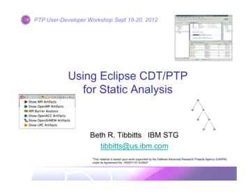
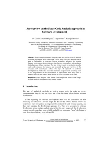
Structural EngineerEstimates, magnitude anddirection of loads:Estimates soil resistance andcalculates size, length and quantityof piles to resist the given loads.Any SCOUR ?Any SET UPThe factored resistance must be greaterthan the factored applied loads !Professor's Driven Pile Institute, Utah State UniversityGeotechnical Engineer
TWO STATIC ANALYSISARE OFTEN REQUIRED1. Design stage soil profile with sourable and/orunsuitable soils removed – establish a pile tipelevation to accommodate the appropriate load(LRFD, ASD)2. Construction stage soil profile, establish thesoil resistance provided by soil profile at time ofpile installation. This is the “target” resistanceand includes scourable and unsuitable soils. Thisvalue should be shown on the plans.
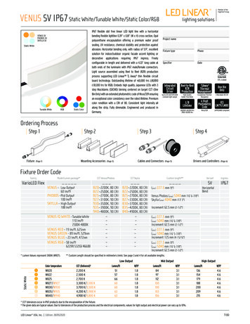
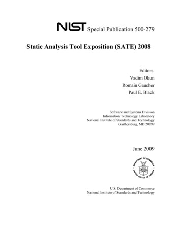
BridgePier1. Calculate the requiredpile length to accommodatethe factored load. Ignoreresistance provided byscourable material.Estimated MaximumScour DepthContractor’s “Target”2. Given the required lengthnow include the resistance ofscourable soils when estimatingsoil resistance at time ofDriving. (show on plans)Professor's Driven Pile Institute, Utah State UniversityTWO STATIC ANALYSIS REQUIRED
LOAD TRANSFERThe ultimate pile capacity is typically expressed asthe sum of the shaft and toe resistances:Qu Rs RtThis may also be expressed in terms of unitresistances:Qu fs As qt AtThe above equations assume that the ultimate shaftand toe resistances are simultaneously developed.
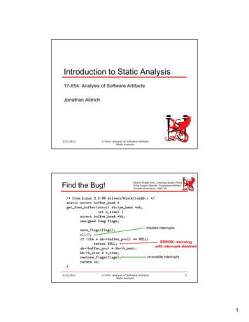
LOADTRANSFERQuAxial Loadvs DepthSoil Resistancevs DepthRs 0RsRtRtUniformRt9-9RsTriangularRtRs
DESIGN SOIL STRENGTHPARAMETERSMost of the static analysis methods in cohesionlesssoils use the soil friction angle determined fromlaboratory tests or SPT N values.In coarse granular deposits, the soil friction angleshould be chosen conservatively.What does this mean ?
DESIGN SOIL STRENGTHPARAMETERSIn soft, rounded gravel deposits, use a maximumsoil friction angle, , of 32 for shaft resistancecalculations.In hard, angular gravel deposits, use a maximumfriction angle of 36 for shaft resistancecalculations.
DESIGN SOIL STRENGTHPARAMETERSIn cohesive soils, accurate assessments of the soilshear strength and consolidation properties areneeded for static analysis.The sensitivity of cohesive soils should be knownduring the design stage so that informedassessments of pile driveability and soil setup canbe made.
DESIGN SOIL STRENGTHPARAMETERSFor a cost effective design with any static analysismethod, the foundation designer must considertime dependent soil strength changes.Ignore set up --- uneconomicalIgnore relaxation --- unsafe
Static Analysis- Single PilesMethods for estimating axial staticresistance of soils
Soil Mechanics Review Angle of friction Undrained shear strength Unconfined Compression Strength
Cohesionless Soils, Drained StrengthNormal Force, NF NμFriction Force, Fμ coefficient of friction betweenmaterial 1 and material 212FTan ( ) F/NF N TAN ( ) NSoil on Soil, we use phi angle such that TAN ( ) isSoil on Pile, we use δcoefficient of friction betweenmaterials 1 and 2
Cohesive Soils, Undrained StrengthF zerocNF Friction resistance (stress) N Normal force (stress)C is independent of overburden pressures (i.e. N)c cohesion, stickiness, soil / soila adhesion, stickiness, soil / pile
Unconfined CompressionStrengthσ1σ3zeroCC cohesion ½ quσ3Maximum σ1 unconfinedcompression strength, qu
STATIC CAPACITYOF PILES INCOHESIONLESS SOILS
METHODS OF STATIC ANALYSIS FOR PILES IN COHESIONLESS FHWA9-19DesignParametersResults ofSPT tests.NResults ofSPT testsbased of N60values.Chartsprovided byNordlund.Estimate ofPart Theory soil frictionPartangle isExperience needed.AdvantagesDisadvantagesRemarksWidespread use ofSPT test and inputdata availability.Simple method touse.Nonreproducibility ofN values. Notas reliable as theother methodspresented in thischapter.Due to nonreproducibility of Nvalues andsimplifyingassumptions, useshould be limited topreliminaryestimatingpurposes.Widespread use ofSPT test and inputdata availability.Simple method touse.N60 values notalwaysavailable.Simple methodbased oncorrelations with 71static load testresults. Detailsprovided in Section9.7.1.1b.Allows forincreased shaftresistance oftapered piles andincludes effects ofpile-soil frictioncoefficient fordifferent pilematerials.No limiting valueon unit shaftresistance isrecommendedby Nordlund.Soil frictionangle oftenestimated fromSPT data.Good approach todesign that iswidely used.Method is based onfield observations.Details provided inSection 9.7.1.1c.
METHODS OF STATIC ANALYSIS FOR PILES IN COHESIONLESS Soilclassificationand estimatedfriction anglefor β and Ntselection.β value considerspile-soil frictioncoefficient fordifferent pilematerials. Soilresistance relatedto effectiveoverburdenpressure.Results effectedby range in βvalues and inparticular byrange in Ntchosen.Good approach fordesign. Detailsprovided in Section9.7.1.3.Methodsbased onConePenetrationTest (CPT)data.EmpiricalResults ofCPT tests.Testing analogybetween CPT andpile. Reliablecorrelations andreproducible testdata.Limitations onpushing cone intodense strata.Good approach fordesign. Detailsprovided in Section9.7.1.7.9-19
Nordlund Data BasePile TypesTimber, H-piles, Closed-end Pipe,Monotube, Raymond Step-TaperPile SizesPile widths of 250 – 500 mm (10 - 20 in)Pile LoadsUltimate pile capacities of 350 -2700 kN(40 -300 tons)9-25Nordlund Method tends to overpredict capacityof piles greater than 600 mm (24 in)
Nordlund MethodConsiders:1. The friction angle of the soil.2. The friction angle of the sliding surface.3. The taper of the pile.4. The effective unit weight of the soil.5. The pile length.6. The minimum pile perimeter.7. The volume of soil displaced.9-25
d D9-27Qu K CF pdd 0sin ( )Cd d t N ’q A t ptcos
Nordlund MethodFor a pile of uniform cross section ( 0) andembedded length D, driven in soil layers ofthe same effective unit weight and frictionangle, the Nordlund equation becomes:Qu (K δ CF pd sinδ Cd D) (αt N ’q A t pt )9-26RSRT
Nordlund Shaft ResistanceRs Kδ CF pd sinδ Cd DK coefficient of lateral earth pressureFigures 9.11 - 9.14CF correction factor for K when Figure 9.15pd effective overburden pressure at center of layer friction angle between pile and soilCd pile perimeterD embedded pile lengthFigure 9.10
Nordlund Toe ResistanceLesser ofRT T N’q pT ATRT qL AT T dimensionless factorFigure 9.16aN’q bearing capacity factorFigure 9.16bAT pile toe areapT effective overburden pressure at pile toe 150 kPaqL limiting unit toe resistance Figure 9.17
Nordlund Method ProcedureSteps 1 through 6 are for computing shaft resistance and steps7 through 9 are for computing the pile toe resistance (cookbook)STEP 1Delineate the soil profile into layers and determine the angle for each layera. Construct po diagram using procedure described in Section 9.4.b. Correct SPT field N values for overburden pressure using Figure 4.4from Chapter 4 and obtain corrected SPT N' values. Delineate soilprofile into layers based on corrected SPT N' values.c. Determine angle for each layer from laboratory tests or in-situ data.d. In the absence of laboratory or in-situ test data, determine the averagecorrected SPT N' value, N', for each soil layer and estimate anglefrom Table 4-5 in Chapter 4.9-28
Nordlund Method ProcedureSTEP 10 Compute the ultimate capacity,Qu. Qu Rs RtSTEP 11 Compute the allowable designload, Qa.Qa Qu / Factor of Safety (ASD)9-31
STATIC CAPACITYOF PILES INCOHESIVE SOILS
METHODS OF STATIC ANALYSIS FOR PILES IN COHESIVE rical,total stressanalysis.Undrained shearstrength estimateof soil is needed.Adhesioncalculated fromFigures 9.18 and9.19.EffectiveStressMethod.SemiEmpirical,based oneffectivestress atfailure.Methodsbased onConePenetrationTest data.Empirical.FHWA9-42Method ofObtainingDesign ParametersAdvantagesDisadvantagesRemarksSimple calculationfrom laboratoryundrained shearstrength values toadhesion.Wide scatter inadhesion versusundrained shearstrengths inliterature.Widely usedmethoddescribed inSection9.7.1.2a.β and Nt valuesare selected fromTable 9-6 based ondrained soilstrength estimates.Ranges in β andNt values formost cohesivesoils are relativelysmall.Range in Ntvalues for hardcohesive soilssuch as glacialtills can be large.Good designapproachtheoreticallybetter thanundrainedanalysis.Details inSection9.7.1.3.Results of CPTtests.Testing analogybetween CPT andpile.Reproducible testdata.Cone can bedifficult toadvance in veryhard cohesivesoils such asglacial tills.Goodapproach fordesign.Details inSection9.7.1.7.
Tomlinson or α-MethodUnit Shaft Resistance, fs:fs ca αcuWhere:ca adhesion (Figure 9.18)α empirical adhesion factor (Figure 9.19)9-41
Tomlinson or α-MethodShaft Resistance, Rs:Rs fs AsWhere:As pile surface area in layer(pile perimeter xlength)
Tomlinson or α-Method (US)Figure 9.18Concrete, Timber, Corrugated Steel PilesSmooth Steel PilesD distance from ground surface to bottom ofclay layer or pile toe, whichever is lessb Pile Diameter
Tomlinson or α-MethodUnit Toe Resistance, qt:qt cu NcWhere:cu undrained shear strength of the soil at pile toeNc dimensionless bearing capacity factor(9 for deep foundations)
Tomlinson or α-MethodToe Resistance, Rt:Rt qt AtThe toe resistance in cohesive soils is sometimes ignoredsince the movement required to mobilize the toe resistanceis several times greater than the movement required tomobilize the shaft resistance.
Tomlinson or α-MethodRu RS RTandQa RU / FS
DRIVEN COMPUTER PROGRAMDRIVEN uses the FHWA recommended Nordlund(cohesionless) and α-methods (cohesive).Can be used to calculate the static capacity ofopen and closed end pipe piles, H-piles, circular orsquare solid concrete piles, timber piles, andMonotube piles.Analyses can be performed in SI or US units.Available at: www.fhwa.dot.gov/bridge/geosoft.htm9-56
The Pile Design is notcomplete until the pilehas been driven –that’s when we can estimatethe “capacity” (E.O.D)
STATIC ANALYSIS –SINGLE PILESLATERAL CAPACITYMETHODSReference Manual Chapter 9.7.39-82
Lateral Capacity of Single Piles Potential sources of lateral loads includevehicle acceleration & braking, windloads, wave loading, debris loading, iceforces, vessel impact, lateral earthpressures, slope movements, andseismic events. These loads can be of the samemagnitude as axial compression loads.
Lateral Capacity of Single PilesSoil, pile, and load parameters significantlyaffect lateral capacity.– Soil Parameters Soil type & strength Horizontal subgrade reaction– Pile Parameters Pile propertiesPile head conditionMethod of installationGroup action– Lateral Load Parameters Static or Dynamic Eccentricity
Lateral Capacity of Single PilesDesign Methods– Lateral load tests– Analytical methods Broms’ method, 9-86, (long pile, short pile) Reese’s COM624P method LPILE program FB-PIER9-85
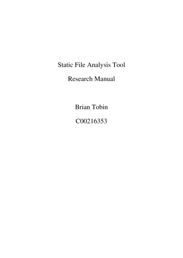
Short pile – soil failsLong pile – pile fails
Figure 9.36 Soil Resistance to a Lateral Pile Load (adapted from Smith, 1989)9-83
NIM
Figure 9.44 LPILE Pile-Soil Model9-101
NIM
We have n equations and (n 4) unknownsBOUNDARY CONDITIONS (long pile)@ Pile BottomMoment 0Shear 0@ Pile Top?
Figure 9.45 Typical p-y Curves for Ductile and Brittle Soil (after Coduto, 1994)9-102
IntegrateDifferentiateFigure 9.36 Graphical Presentation of LPILE Results (Reese, et al. 2000)9-92
LET’S EAT !!
BASICS OF STATIC ANALYSIS Static capacity is the sum of the soil/rock resistances along the pile shaft and at the pile toe. Static analyses are performed to determine ultimate pile capacity and the pile group response to applied loads. The ultimate capacity of a pile and pile group is the smaller of the soil rock medium to support the pile