Transcription
DESIGN, INSTALLATION AND TESTING OFHELICAL PILES & ANCHORSPresented by: Donald A. Deardorff, P.E.CHANCE Civil ConstructionCentralia, MO USA
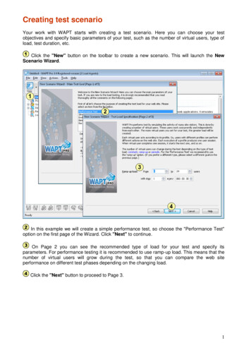
Historical Perspective 1st Recorded Screw Pile was by Alexander Mitchell in 1836for Moorings and then applied by Mitchell to Maplin SandsLighthouse in England in 1838. In 1851, a Screw Pile Light House was established as theBridgeport Harbor Light, Connecticut on the west side ofthe harbor. In the 1850’s, More Than 100 Light Houses wereConstructed Along the East Coast, the Florida Coast andthe Gulf of Mexico using Screw Pile Foundations.CHANCE Civil Construction
Mitchell’s Screw Pile - 1836CHANCE Civil Construction
“on Submarine Foundations; particularly Screw-Pile andMoorings”, by Alexander Mitchell, Civil Engineer andArchitects Journal, Vol. 12, 1848.“ whether this broad spiral flange, or “Ground Screw,” as it maybe termed, be applied to support a superincumbent weight,or be employed to resist an upward strain, its holding powerentirely depends upon the area of its disc, the nature of theground into which it is inserted, and the depth to which it isforced beneath the surface.”CHANCE Civil Construction
Mitchell Lighthouse atHooper’s Strait, MarylandInstalled 1870’sRemoved 1960’sMuseum at St. Michael, MDExtracted Cast Iron Screw Pile, 30” DiameterCHANCE Civil Construction
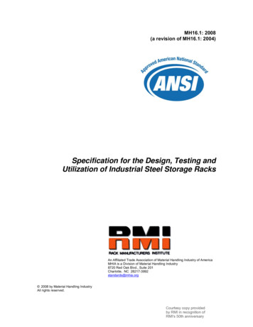
What is a Helical Anchor/Pile? A helical anchor/pile consistsof one or more helix-shapedbearing plates attached to acentral shaft, which is installedby rotating or "torqueing" intothe ground. Each helix isattached near the tip, isgenerally circular in plan, andformed into a helix with adefined pitch. Helicalanchors/piles derive their loadcarrying capacity through bothend bearing on the helix platesand skin friction on the shaft.CHANCE Civil Construction
ExtendableHelical Piles –Either Square orRound ShaftNO MORE THAN 6HELICES PER ANCHORLead SectionHelical ExtensionExtensionCHANCE Civil Construction
CHANCE Helical ProductsStandard Helix DiametersStandard Helix Sizes andProjected AreasDIAMETERin (cm)AREAft2 (m2)6 (15)0.185 (0.0172)8 (20)0.336 (0.0312)10 (25)0.531 (0.0493)12 (30)0.771 (0.0716)14 (35)1.049 (0.0974)16 (40)1.385 (0.1286)CHANCE Civil Construction
Type SS Series - Shaft Mechanical PropertiesSS125SS1375SS5SS150SS175SS200SS225Square ShaftSquare ShaftSquare ShaftSquare ShaftSquare ShaftSquare ShaftSquare ShaftTorque Rating 075100150*200*75*100*Ultimate Tension Strength Based on Bolt Strength * (kip)60757070100Allowable Load Tension Load Based on Bolt Strength † (kip)3037.5353550Tension/Compression Capacity Limit Based on Shaft Torque Rating ** (kip)40555570110Allowable Tension/Compression Load Limit Based on Shaft Torque Rating † (kip)2027.527.53555Highlighted Product Series are most common* Based on Mechanical Strength of Coupling.** Based on Shaft Torque Rating – Tension/Compression Shaft Torque Rating x Kt“Default “ Kt for the SS Series 10 ft-1† Allowable Loads are based on a Factor of Safety of two (2).CHANCE Civil Construction
Type RS Series - Shaft Mechanical RS4500.337Round ShaftRound ShaftRound ShaftRound ShaftRound Shaft13,00023,000Torque Rating (ft-lb)4,5005,5007,500Ultimate Tension Strength Based on Bolt Strength * (kip)5060100120140Allowable Load Tension Load Based on Bolt Strength † (kip)2530506070Tension/Compression Capacity Limit Based on Shaft Torque Rating ** (kip)36446091138Allowable Tension/Compression Load Limit Based on Shaft Torque Rating † (kip)18223045.569Highlighted Product Series are most common.* Based on Mechanical Strength of Coupling.** Based on Shaft Torque Rating – Tension/Compression Shaft Torque Rating x Kt“Default “ Kt for the RS2875.XXX Series 8 ft-1; for the RS3500.300 Series 7 ft-1;for the RS4500.337 Series 6 ft-1.† Allowable Loads are based on a Factor of Safety of two (2).RS2875.276 and RS8625 SeriesNow availableCHANCE Civil Construction
TYPE “SS/RS” COMBINATION SERIESType SS5/SS150 to RS2875.203 Combination SeriesandType SS175/SS200 to RS3500.300 Combination SeriesPile Assembly with RS Transition CouplerTransition Couplings - Torque RatingsCATALOG NUMBERDESCRIPTIONTORQUE RATINGSC278-0150SS5/SS150 square shaft to a RS2875.203 roundshaft5,500 ft-lbsT107-0808SS175 square shaft to a RS3500.300 round shaft11,000 ft-lbsT107-0809SS200 square shaft to a RS3500.300 round shaft13,000 ft-lbsMechanical Ratings of Combination SeriesDESCRIPTIONULTIMATE TENSIONSTRENGTH* lbs (kn)TENSION/COMPRESSIONLIMIT** lbs (kn)SS5/RS2875.20360,000. (267)44,000. (196)SS150/RS2875.20360,000. (267)44,000. (196)SS175/RS3500.300100,000. (445)91,000. (405)SS200/RS3500.300120,000. (534)91,000. (405)* Based on Mechanical Strength of Coupling.** Based on Shaft Torque Rating – Tension/Compression Shaft Torque Rating x Kt“Default “ Kt for the SS Series 10 ft-1, for the RS2875 Series 8 ft-1, for theRS3500 Series 7 ft-1.CHANCE Civil Construction
ADVANTAGES – HELICAL PILES& ANCHORS Quick, Easy TurnkeyInstallation Immediate Loading Small InstallationEquipment Pre-Engineered System Easily Field Modified Torque-to CapacityCorrelation Install in Any Weather Solution for:– Restricted Access Sites– High Water Table– Weak Surface Soils Environmentally FriendlyNo VibrationNo Spoils to RemoveNo ConcreteCHANCE Civil Construction
Helical Screw Piles for NewConstructionSquare Shaft Helical PileRound Pipe Shaft Helical PileCHANCE Civil Construction
Ft. Sill, OK Troop Housing and Headquarters Facilities Three manufactured housing companies Four different floor plans Three different sites Three different pile types (RS2875, RS3500, RS4500 and SS5) Tension, Compression and Lateral LoadsCHANCE Civil Construction
Ft. Sill Troop HousingCHANCE Civil Construction
CHANCE Civil Construction
CHANCE Civil Construction
New Construction - Slabs and FoundationsAccess LimitationsScrew Piles Supporting Structural SlabCHANCE Civil Construction
CHANCE Civil Construction
Foundation UnderpinningCHANCE Civil Construction
Remedial Repair Bracket – C150-0121SS5, SS150 (1-1/2 Square Shaft) & RS2875.203 Round Shaft PileCHANCE Civil Construction
Foundation Underpinning with Helical PilesScrew FoundationInstallation withPortable InstallerCHANCE Civil Construction
Foundation Underpinning with Helical PilesRaising Building withRepair BracketsRepair BracketsCHANCE Civil Construction
Foundation Underpinning BracketsSTANDARD-DUTYFOUNDATION REPAIR BRACKETFOR 1 ½” SHAFTRATED CAPACITIES:20,000 LB. WITH SS5 Helical Piles25,000LB. WITH SS150 Helical PilesFOR 1 ¾” SHAFTRATED CAPACITY: 30,000LB.HEAVY-DUTYFOUNDATION REPAIR BRACKETFOR 1 ¾” SHAFTRATED CAPACITY: 40,000LB.CHANCE Civil Construction
Baptist ChurchBurlington, OntarioCHANCE Civil Construction
Walkways for WetlandsCHANCE Civil Construction
Tie Down & Buoyancy ControlCHANCE Civil Construction
Band Shell at the CapitolCHANCE Civil Construction
CHANCE Helical AnchorsOther Tension ApplicationsPipeline Buoyancy ControlCHANCE Civil Construction
Pipeline Buoyancy ControlCHANCE Civil Construction
THE QUINCY MA SEWER PIPELINE Over 1000 HS Helical Pulldown Micropiles used Soils consisted of mixed soils-organic silt, peat and clay.CHANCE Civil Construction
CHANCE Helical Products(Tension & Compression)CHANCE Civil Construction
5 Guys ContemplateAn AnchorRodCivil ConstructionCHANCE
6 Helices MaxCHANCE Civil Construction
CHANCE Civil Construction
Soil Screws - Section DetailCHANCE Civil Construction
Soil Screws for Soil Nail WallsCHANCE Civil Construction
Increasing Size of Building LotAlpharetta, GACHANCE Civil Construction
HELICAL PULLDOWN MICROPILES
HELICAL PULLDOWN MICROPILES Screw Pile Foundation Installation Method Used toIncrease the Section Modulus of a Standard SS or PipeShaft. Patent Protected– U.S. 5,707,180; Methods and Apparatus– Other U.S. and Foreign Patents Pending Method of Displacing Soil Around the Anchor Shaft andReplacing with Grout Column.– Soil is Displaced by “Lead Displacement Plate”.– “Extension Displacement Plates” Serve as Centralizersand Provide the Means for Which the Grout is “PulledDown”.CHANCE Civil Construction
GROUTRESERVOIRGROUT RESEVOIRNEAT CEMENTGROUT (VERYFLOWABLE)EXTENSIONDISPLACEMENTPLATESQUARE TESCHANCE Civil Construction
Installing Lead CaseCHANCE Civil Construction
Installing Top Case(Grout Reservoir)Adding CentralizerCHANCE Civil Construction
Pouring GroutJoint PackingCHANCE Civil Construction
Installing Shaft ExtensionGrout “Pulled Down”CHANCE Civil Construction
SOIL CAPACITY INDIVIDUAL BEARINGMETHOD
Shallow vs. Deep Helical Anchors/PilesCHANCE Civil Construction
Soil Stress DistributionCHANCE Civil Construction
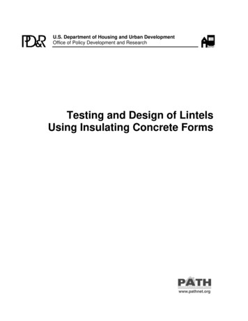
Plate Bearing Capacity ModelMinimumDepth5DUCfD Total Capacity Equal to Sumof Individual Helix BearingCapacities Model valid for both tensionand compression Helix Spacing 3D1 Min. Depth 5D (also needto be deeper than zone ofseasonal moisturefluxuation) Capacity (UCf) Due toFriction Along Shaft Zero.HelixSpacingD1CHANCE Civil Construction
Individual Bearing (Chance) MethodDetermine End Bearing Capacity of Helical ConfigurationGeneral Bearing Capacity Equation:Qult A (CNc qNq (½)γBNγ)where: A Area of footing C Cohesion q Overburden Pressure (γD)(D Depth of footing below groundline) γ Unit Weight of Soil B Width of Footing Nc, Nq, & Nγ Bearing Capacity Factors(Nc 9 for ratio of top helix depth to helix diameter 5)CHANCE Civil Construction
Individual Bearing (Chance) Method“Individual Bearing Plate” MethodQult Qhwhere: Qult Total Multi-helix Anchor/Pile Ultimate Capacity Qh Individual Helix Ultimate CapacityQh Ah (NcC γDNq) QsQh Ah (9C γDNq) Qswhere: Ah Projected Area of Helix Nc 9 for ratio of top helix depth to helix dia. 5 D Depth of Helix Plate below Groundline Nq Bearing Capacity Factor for Sand Qs Upper Mechanical Limit determined by Helix StrengthCHANCE Civil Construction
13Bearing Capacity Factor Curve Nq vs. Angle of InternalFriction Cohesionless Soils Adapted from G. G.Meyerhof Factors forDriven Piles in his paperBearing Capacity and Settlementof Pile Foundations, 1976 Equation:Nq 0.5 (12*φ)φ/54CHANCE Civil Construction
FACTOR OF SAFETY Select an Appropriate Factor of Safety (FS) toApply to the Ultimate Capacity of the HelicalAnchor/Pile to Develop the required Design, orWorking Capacity per Anchor/Foundation. In general, Chance Civil Construction recommendsa minimum FS of 2 for permanent construction and1.5 for temporary construction.CHANCE Civil Construction
HeliCAP v2.0 Helical CapacityDesign Software Microsoft Windows BasedBearing, Uplift, and FrictionCapacity Software 4 Types of Helical ApplicationsCompression, Tension,Tiebacks, and Soil Screws Within those applications canalso calculate friction capacity ofa grout column or steel pipeshaft. New Based on soil and anchor/pileinputs the program returnstheoretical capacities andinstallation torque.CHANCE Civil Construction
INSTALLATION TORQUECORRELATION TOCAPACITY
Helical Piles & Anchors - HOWTHEY WORK Low Soil Displacement FoundationElement Specifically Designed to MinimizeDisturbance During Installation Consists of One or More Helix PlatesAttached to a Central Steel Shaft Rotated, or “Screwed” into Soil Much Likea Wood Screw Driven into a Piece ofWoodCHANCE Civil Construction
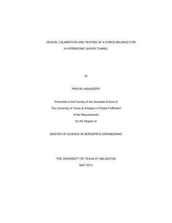
INSTALLATION ENERGY Must Equal the Energy Required to Penetratethe Soil, plus the Energy Loss Due to Friction Provided by the Machine – Consists of TwoParts:– Rotation Energy – Supplied by the Torque Motor Rotation and Inclined Plane of Helix Provides DownwardThrust A.k.a. INSTALLATION TORQUE– Downward Force, or Crowd – Supplied by theMachineCHANCE Civil Construction
MACHINECROWDTORQUEMOTORTORQUEINDICATORFOUR HELIXLEAD SECTIONCHANCE Civil Construction
INSTALLATION TORQUE VS.ULTIMATE CAPACITYThe Torque Required to Install aHelical Pile or Anchor is EmpiricallyRelated to Its Ultimate Capacity.¾Qult KtT– Where: Qult Ultimate Capacity [lb (kN)] Kt Empirical Torque Factor [ft-1 (m-1)]––––“Default” Value 10 (33) for Type “SS”“Default” Value 8 (26) for 2-7/8” Pipe Shaft“Default” Value 7 (23) for 3-1/2” Pipe Shaft“Default” Value 6-7 (20-23) for 4-1/2” Pipe Shaft T Installation Torque, [ft-lb (kN-m)]CHANCE Civil Construction
INSTALLATION TORQUE VS.ULTIMATE CAPACITY The Value of Kt is not a Constant - May Rangefrom 3 to 20 ft.-1 (10 to 66 m-1). Depends on:– Soil Conditions Type SS––––Normally Consolidated Clay – Kt 10Overconsolidated Clay – Kt 12-14Sensitive Clay – Kt 10Sands – Kt 12 – Central Steel Shaft/Helix Size Kt Inversely Related to Shaft and Helix Size– Helix Thickness Kt Inversely Related to Helix Thickness– Application (Tension or Compression) Compression Capacity is Generally Higher Than TensionCapacityCHANCE Civil Construction
TORQUE - ADVANTAGES Provides Excellent Field Control Method ofInstallation Monitors Soil Conditions¾ Torque is a Direct Measure of Soil ShearStrength Predicts Holding Capacity of the Soil Helical Piles/Anchors Can be Installed toSpecified TorqueCHANCE Civil Construction
TORQUE - REQUIREMENTS Requires Competent, Well-Trained Installers– CHANCE Certification Program Requires Installation in the Field to DetermineCapacity Requires Torque Monitoring EquipmentCHANCE Civil Construction
RELIABILITY OFTORQUE/CAPACITY MODEL Uplift Capacity of Helical Anchors in Soil [Hoyt &Clemence 1989]–––––Analyzed 91 Load Tests24 Different Test SitesSand, Silt, and Clay Soils RepresentedCalculated Capacity Ratio (Qact/Qcalc)Three Different Load Capacity Models Cylindrical Shear Individual Bearing Torque Correlat
What is a Helical Anchor/Pile? A helical anchor/pile consists of one or more helix-shaped bearing plates attached to a central shaft, which is installed by rotating or "torqueing" into the ground. Each helix is attached near the tip, is generally circular in plan, and formed into a helix with a defined pitch. Helical