![Pile Foundation Design[1] - ITD](/img/29/pilefoundationdesign.jpg)
Transcription
Pile Foundation Design: A Student GuideAscalew Abebe & Dr Ian GN SmithSchool of the Built Environment, Napier University, Edinburgh(Note: This Student Guide is intended as just that - a guide for students of civilengineering.Use it as you see fit, but please note that there is no technical support available toanswer any questions about the guide!)
PURPOSE OF THE GUIDEThere are many texts on pile foundations. Generally, experience shows us thatundergraduates find most of these texts complicated and difficult tounderstand.This guide has extracted the main points and puts together the whole process ofpile foundation design in a student friendly manner.The guide is presented in two versions: text-version (compendium from) andthis web-version that can be accessed via internet or intranet and can be used asa supplementary self-assisting students guide.STRUCTURE OF THE GUIDEIntroduction to pile foundationsPile foundation designLoad on pilesSingle pile designPile group designInstallation-test-and factor of safetyPile installation methodsTest pilesFactors of safetyChapter 1 Introduction to pile foundations1.1 Pile foundations
1.2 Historical1.3 Function of piles1.4 Classification of piles1.4.1 Classification of pile with respect to load transmission and functional behaviour1.4.2 End bearing piles1.4.3 Friction or cohesion piles1.4.4 Cohesion piles1.4.5 Friction piles1.4.6 Combination of friction piles and cohesion piles1.4.7 .Classification of pile with respect to type of material1.4.8 Timber piles1.4.9 Concrete pile1.4.10 Driven and cast in place Concrete piles1.4.11 Steel piles1.4.12 Composite piles1.4.13 Classification of pile with respect to effect on the soil1.4.14 Driven piles1.4.15 Bored piles1.5 Aide to classification of piles1.6 Advantages and disadvantages of different pile material1.7 Classification of piles - ReviewChapter 2 Load on piles2.1 Introduction2.2 Pile arrangementChapter 3 Load Distribution3.1 Pile foundations: vertical piles only3.2 Pile foundations: vertical and raking piles3.3 Symmetrically arranged vertical and raking piles3.3.1 Example on installation errorChapter 4 Load on Single Pile4.1 Introduction4.2 The behaviour of piles under load4.3 Geotechnical design methods4.3.1 The undrained load capacity (total stress approach)4.3.2 Drained load capacity (effective stress approach)4.3.3 Pile in sand4.4 Dynamic approachChapter 5 Single Pile Design5.1 End bearing piles5.2 Friction piles5.3 Cohesion piles5.4 Steel piles5.5 Concrete piles5.5.1 Pre-cast concrete piles5.6 Timber piles (wood piles)5.6.1 Simplified method of predicting the bearing capacity of timber pilesChapter 6 Design of Pile Group6.1 Bearing capacity of pile groups6.1.1 Pile group in cohesive soil6.1.2 Pile groups in non-cohesive soil6.1.3 Pile groups in sandChapter 7 Pile Spacing and Pile Arrangement
Chapter 8 Pile Installation Methods8.1 Introduction8.2 Pile driving methods (displacement piles)8.2.1 Drop hammers8.2.2 Diesel hammers8.2.3 Pile driving by vibrating8.3 Boring methods (non-displacement piles)8.3.1 Continuous Flight Auger (CFA)8.3.2 Underreaming8.3.3 C.H.PChapter 9 Load Tests on Piles9.1 Introduction9.1.1 CRP (constant rate of penetration)9.1.2 MLT, the maintained increment load testChapter 10 Limit State Design10.1 Geotechnical category GC 110.2 Geotechnical category GC 210.3 Geotechnical category GC 310.3.1 Conditions classified as in Eurocode 710.4 The partial factors γ m, γ n, γ RdIntroduction to pile foundationsObjectives: Texts dealing with geotechnical and ground engineeringtechniques classify piles in a number of ways. The objective of this unit is that inorder to help the undergraduate student understand these classifications usingmaterials extracted from several sources, this chapter gives an introduction topile foundations.1.1 Pile foundationsPile foundations are the part of a structure used to carry and transfer the load ofthe structure to the bearing ground located at some depth below groundsurface. The main components of the foundation are the pile cap and the piles.Piles are long and slender members which transfer the load to deeper soil orrock of high bearing capacity avoiding shallow soil of low bearing capacity Themain types of materials used for piles are Wood, steel and concrete. Piles madefrom these materials are driven, drilled or jacked into the ground and connectedto pile caps. Depending upon type of soil, pile material and load transmittingcharacteristic piles are classified accordingly. In the following chapter we learnabout, classifications, functions and pros and cons of piles.1.2 HistoricalPile foundations have been used as load carrying and load transferring systemsfor many years.
In the early days of civilisation[2], from the communication, defence or strategicpoint of view villages and towns were situated near to rivers and lakes. It wastherefore important to strengthen the bearing ground with some form of piling.Timber piles were driven in to the ground by hand or holes were dug and filledwith sand and stones.In 1740 Christoffoer Polhem invented pile driving equipment which resembled todays pile driving mechanism. Steel piles have been used since 1800 andconcrete piles since about 1900.The industrial revolution brought about important changes to pile driving systemthrough the invention of steam and diesel driven machines.More recently, the growing need for housing and construction has forcedauthorities and development agencies to exploit lands with poor soilcharacteristics. This has led to the development and improved piles and piledriving systems. Today there are many advanced techniques of pile installation.1.3 Function of pilesAs with other types of foundations, the purpose of a pile foundations is:to transmit a foundation load to a solid groundto resist vertical, lateral and uplift loadA structure can be founded on piles if the soil immediately beneath its basedoes not have adequate bearing capacity. If the results of site investigationshow that the shallow soil is unstable and weak or if the magnitude of theestimated settlement is not acceptable a pile foundation may becomeconsidered. Further, a cost estimate may indicate that a pile foundation may becheaper than any other compared ground improvement costs.In the cases of heavy constructions, it is likely that the bearing capacity of theshallow soil will not be satisfactory, and the construction should be built onpile foundations. Piles can also be used in normal ground conditions to resisthorizontal loads. Piles are a convenient method of foundation for works overwater, such as jetties or bridge piers.1.4 Classification of piles1.4.1 Classification of pile with respect to load transmission andfunctional behaviourEnd bearing piles (point bearing piles)
Friction piles (cohesion piles )Combination of friction and cohesion piles1.4.2 End bearing pilesThese piles transfer their load on to a firm stratum located at a considerabledepth below the base of the structure and they derive most of their carryingcapacity from the penetration resistance of the soil at the toe of the pile (seefigure 1.1). The pile behaves as an ordinary column and should be designed assuch. Even in weak soil a pile will not fail by buckling and this effect need onlybe considered if part of the pile is unsupported, i.e. if it is in either air or water.Load is transmitted to the soil through friction or cohesion. But sometimes, thesoil surrounding the pile may adhere to the surface of the pile and causes"Negative Skin Friction" on the pile. This, sometimes have considerable effecton the capacity of the pile. Negative skin friction is caused by the drainage ofthe ground water and consolidation of the soil. The founding depth of the pile isinfluenced by the results of the site investigate on and soil test.1.4.3 Friction or cohesion pilesCarrying capacity is derived mainly from the adhesion or friction of the soil incontact with the shaft of the pile (see fig 1.2).Figure 1-1 End bearing pilesFigure 1-2 Friction or cohesion pile1.4.4 Cohesion pilesThese piles transmit most of their load to the soil through skin friction. Thisprocess of driving such piles close to each other in groups greatly reduces theporosity and compressibility of the soil within and around the groups. Thereforepiles of this category are some times called compaction piles. During theprocess of driving the pile into the ground, the soil becomes moulded and, as aresult loses some of its strength. Therefore the pile is not able to transfer the
exact amount of load which it is intended to immediately after it has beendriven. Usually, the soil regains some of its strength three to five months after ithas been driven.1.4.5 Friction pilesThese piles also transfer their load to the ground through skin friction. Theprocess of driving such piles does not compact the soil appreciably. Thesetypes of pile foundations are commonly known as floating pile foundations.1.4.6 Combination of friction piles and cohesion pilesAn extension of the end bearing pile when the bearing stratum is not hard, suchas a firm clay. The pile is driven far enough into the lower material to developadequate frictional resistance. A farther variation of the end bearing pile is pileswith enlarged bearing areas. This is achieved by forcing a bulb of concrete intothe soft stratum immediately above the firm layer to give an enlarged base. Asimilar effect is produced with bored piles by forming a large cone or bell at thebottom with a special reaming tool. Bored piles which are provided with a bellhave a high tensile strength and can be used as tension piles (see fig.1-3)Figure 1-3 under-reamed baseenlargement to a bore-and-cast-in-situpile1.4.7 Classification of pile with respect to type of material TimberConcreteSteelComposite piles1.4.8 Timber piles
Used from earliest record time and still used for permanent works in regionswhere timber is plentiful. Timber is most suitable for long cohesion piling andpiling beneath embankments. The timber should be in a good condition andshould not have been attacked by insects. For timber piles of length less than14 meters, the diameter of the tip should be greater than 150 mm. If the lengthis greater than 18 meters a tip with a diameter of 125 mm is acceptable. It isessential that the timber is driven in the right direction and should not be driveninto firm ground. As this can easily damage the pile. Keeping the timber belowthe ground water level will protect the timber against decay and putrefaction. Toprotect and strengthen the tip of the pile, timber piles can be provided with toecover. Pressure creosoting is the usual method of protecting timber piles.1.4.9 Concrete pilePre cast concrete Piles or Pre fabricated concrete piles : Usually of square (seefig 1-4 b), triangle, circle or octagonal section, they are produced in short lengthin one metre intervals between 3 and 13 meters. They are pre-caste so thatthey can be easily connected together in order to reach to the required length(fig 1-4 a) . This will not decrease the design load capacity. Reinforcement isnecessary within the pile to help withstand both handling and driving stresses.Pre stressed concrete piles are also used and are becoming more popular thanthe ordinary pre cast as less reinforcement is required .Figure 1-4 a) concrete pile connecting detail. b) squared pre-cast concert pileThe Hercules type of pile joint (Figure 1-5) is easily and accurately cast into thepile and is quickly and safely joined on site. They are made to accuratedimensional tolerances from high grade steels.
Figure 1-5 Hercules type of pile joint1.4.10 Driven and cast in place Concrete pilesTwo of the main types used in the UK are: West’s shell pile : Pre cast,reinforced concrete tubes, about 1 m long, are threaded on to a steel mandreland driven into the ground after a concrete shoe has been placed at the front ofthe shells. Once the shells have been driven to specified depth the mandrel iswithdrawn and reinforced concrete inserted in the core. Diameters vary from325 to 600 mm.Franki Pile: A steel tube is erected vertically over the place where the pile is tobe driven, and about a metre depth of gravel is placed at the end of the tube. Adrop hammer, 1500 to 4000kg mass, compacts the aggregate into a solid plugwhich then penetrates the soil and takes the steel tube down with it. When therequired depth has been achieved the tube is raised slightly and the aggregatebroken out. Dry concrete is now added and hammered until a bulb is formed.Reinforcement is placed in position and more dry concrete is placed andrammed until the pile top comes up to ground level.1.4.11 Steel piles
Steel piles: (figure 1.4) steel/ Iron piles are suitable for handling and driving inlong lengths. Their relatively small cross-sectional area combined with their highstrength makes penetration easier in firm soil. They can be easily cut off orjoined by welding. If the pile is driven into a soil with low pH value, then there isa risk of corrosion, but risk of corrosion is not as great as one might think.Although tar coating or cathodic protection can be employed in permanentworks.It is common to allow for an amount of corrosion in design by simply overdimensioning the cross-sectional area of the steel pile. In this way the corrosionprocess can be prolonged up to 50 years. Normally the speed of corrosion is0.2-0.5 mm/year and, in design, this value can be taken as 1mm/yeara) X- crosssectionb) H - crosssectionc) steel pipeFigure 1-6 Steel piles cross-sections1.4.12 Composite pilesCombination of different materials in the same of pile. As indicated earlier, partof a timber pile which is installed above ground water could be vulnerable toinsect attack and decay. To avoid this, concrete or steel pile is used above theground water level, whilst wood pile is installed under the ground water level(see figure 1.7).
Figure 1-7 Protecting timber piles from decay:a) by pre-cast concrete upper section above water level.b) by extending pile cap below water level1.4.13 Classification of pile with respect to effect on the soilA simplified division into driven or bored piles is often employed.1.4.14 Driven pilesDriven piles are considered to be displacement piles. In the process of drivingthe pile into the ground, soil is moved radially as the pile shaft enters theground. There may also be a component of movement of the soil in the verticaldirection.
Figure 1-8 driven piles1.4.15 Bored pilesBored piles(Replacement piles) are generally considered to be nondisplacement piles a void is formed by boring or excavation before piles isproduced. Piles can be produced by casting concrete in the void. Some soilssuch as stiff clays are particularly amenable to the formation of piles in this way,since the bore hole walls do not requires temporary support except cloth to theground surface. In unstable ground, such as gravel the ground requirestemporary support from casing or bentonite slurry. Alternatively the casing maybe permanent, but driven into a hole which is bored as casing is advanced. Adifferent technique, which is still essentially non-displacement, is to intrude, agrout or a concrete from an auger which is rotated into the granular soil, andhence produced a grouted column of soil.There are three non-displacement methods: bored cast- in - place piles,particularly pre-formed piles and grout or concrete intruded piles.The following are replacement piles:AugeredCable percussion drillingLarge-diameter under-reamedTypes incorporating pre caste concrete uniteDrilled-in tubes
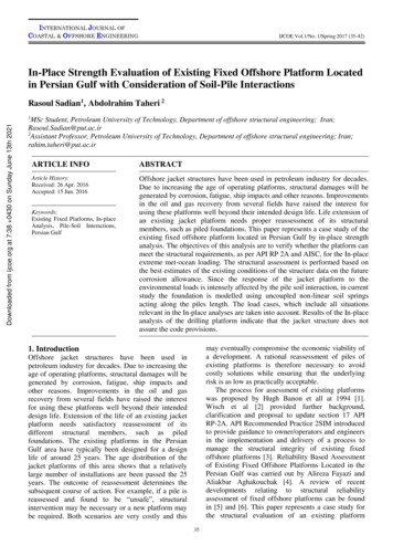
Mini piles1.5 Aide to classification of pilesFigure 1-8. for a quick understanding of pile classification, a hierarchicalrepresentation of pile types can be used. Also advantages and disadvantagesof different pile materials is given in section 1.6.
Figure 1-9 hierarchical representation of pile types1.6 Advantages and disadvantages of different pile material
Wood piles The piles are easy to handle Relatively inexpensive where timber is plentiful. Sections can be joined together and excess length easily removed.-- The piles will rot above the ground water level. Have a limited bearingcapacity.-- Can easily be damaged during driving by stones and boulders.-- The piles are difficult to splice and are attacked by marine borers in saltwater.Prefabricated concrete piles (reinforced) and pre stressed concrete piles.(driven) affected by the ground water conditions. Do not corrode or rot. Are easy to splice. Relatively inexpensive. The quality of the concrete can be checked before driving. Stable in squeezing ground, for example, soft clays, silts and peats pilematerial can be inspected before piling. Can be re driven if affected by ground heave. Construction procedureunaffected by ground water. Can be driven in long lengths. Can be carried above ground level, forexample, through water for marine structures. Can increase the relative density of a granular founding stratum.-- Relatively difficult to cut.-- Displacement, heave, and disturbance of the soil during driving.-- Can be damaged during driving. Replacement piles may be required.-- Sometimes problems with noise and vibration.-- Cannot be driven with very large diameters or in condition of limitedheadroom.
Driven and cast-in-place concrete pilesPermanently cased (casing left in the ground)Temporarily cased or uncased (casing retrieved) Can be inspected before casting can easily be cut or extended to the desiredlength. Relatively inexpensive. Low noise level. The piles can be cast before excavation. Pile lengths are readily adjustable. An enlarged base can be formed which can increase the relative density of agranular founding stratum leading to much higher end bearing capacity. Reinforcement is not determined by the effects of handling or driving stresses. Can be driven with closed end so excluding the effects of GW-- Heave of neighbouring ground surface, which could lead to re consolidationand the development of negative skin friction forces on piles.-- Displacement of nearby retaining walls. Lifting of previously driven piles,where the penetration at the toe have been sufficient to resist upwardmovements.-- Tensile damage to unreinforced piles or piles consisting of green concrete,where forces at the toe have been sufficient to resist upward movements.-- Damage piles consisting of uncased or thinly cased green concrete due to thelateral forces set up in the soil, for example, necking or waisting. Concretecannot be inspected after completion. Concrete may be weakened if artesianflow pipes up shaft of piles when tube is withdrawn.-- Light steel section or Precast concrete shells may be damaged or distorted byhard driving.-- Limitation in length owing to lifting forces required to withdraw casing, nosevibration and ground displacement may a nuisance or may damage adjacentstructures.-- Cannot be driven where headroom is limited.-- Relatively expensive.
-- Time consuming. Cannot be used immediately after the installation.-- Limited length.Bored and cast in -place (non -displacement piles) Length can be readily varied to suit varying ground conditions. Soil removed in boring can be inspected and if necessary sampled or in- situtest made. Can be installed in very large diameters. End enlargement up to two or three diameters are possible in clays. Material of piles is not dependent on handling or driving conditions. Can be installed in very long lengths. Can be installed with out appreciable noise or vibrations. Can be installed in conditions of very low headroom. No risk of ground heave.-- Susceptible to "waisting" or "necking" in squeezing ground.-- Concrete is not placed under ideal conditions and cannot be subsequentlyinspected.-- Water under artesian pressure may pipe up pile shaft washing out cement.-- Enlarged ends cannot be formed in cohesionless materials without specialtechniques.-- Cannot be readily extended above ground level especially in river and marinestructures.-- Boring methods may loosen sandy or gravely soils requiring base grouting toachieve economical base resistance.-- Sinking piles may cause loss of ground I cohesion-less leading to settlementof adjacent structures.Steel piles (Rolled steel section)
The piles are easy to handle and can easily be cut to desired length. Can be driven through dense layers. The lateral displacement of the soilduring driving is low (steel section H or I section piles) can be relatively easilyspliced or bolted. Can be driven hard and in very long lengths. Can carry heavy loads. Can be successfully anchored in sloping rock. Small displacement piles particularly useful if ground displacements anddisturbance critical.-- The piles will corrode,-- Will deviate relatively easy during driving.-- Are relatively expensive.1.7 Classification of piles - Review-Task1. Describe the main function of piles2. In the introduction, it is stated that piles transfer load to the bearingground. State how this is achieved.3. Piles are made out of different materials. In short state theadvantages and disadvantages of these materials.4. Piles can be referred as displacement and non-displacement piles.State the differences and the similarities of these piles5. Piles can be classified as end-bearing piles cohesive or frictionpiles. Describe the differences and similarity of these piles.6. Piles can be classified as bored or driven state the differences.LOAD ON PILES2.1 IntroductionThis section of the guide is divided into two parts. The first part gives briefsummary on basic pile arrangements while part two deals with load distribution onindividual piles.Piles can be arranged in a number of ways so that they can support load imposed
on them. Vertical piles can be designed to carry vertical loads as well as lateralloads. If required, vertical piles can be combined with raking piles to supporthorizontal and vertical forces.often, if a pile group is subjected to vertical force, then the calculation of loaddistribution on single pile that is member of the group is assumed to be the totalload divided by the number of piles in the group. However if a group of piles issubjected to lateral load or eccentric vertical load or combination of vertical andlateral load which can cause moment force on the group which should be takeninto account during calculation of load distribution.In the second part of this section, piles are considered to be part of the structureand force distribution on individual piles is calculated accordingly. Objective: In the first part of this section, considering group of piles withlimited number of piles subjected to vertical and lateral forces, forces actingcentrally or eccentrically, we learn how these forces are distributed on individualpiles.The worked examples are intended to give easy follow through exercise that canhelp quick understanding of pile design both single and group of piles. In thesecond part, the comparison made between different methods used in pile designwill enable students to appreciate the theoretical background of the methods whileexercising pile designing.Learning outcomeWhen students complete this section, they will be able to: Calculate load distribution on group of piles consist of vertical pilessubjected to eccentric vertical load.Calculate load distribution on vertically arranged piles subjected tolateral and vertical forces.Calculate load distribution on vertical and raking piles subjected tohorizontal and eccentric vertical loads.Calculate load distribution on symmetrically arranged vertical andraking piles subjected to vertical and lateral forces2.2 Pile arrangementNormally, pile foundations consist of pile cap and a group of piles. The pile capdistributes the applied load to the individual piles which, in turn,. transfer the load tothe bearing ground. The individual piles are spaced and connected to the pile cap
or tie beams and trimmed in order to connect the pile to the structure at cut-offlevel, and depending on the type of structure and eccentricity of the load, they canbe arranged in different patterns. Figure 2.1 bellow illustrates the three basicformation of pile groups.a) PILE GROUP CONSIST OF ONLY b) PILE GROUP CONSIST OF BOTHVERTICAL PILESVERTICAL AND RAKING PILESc) SYMMETRICALLY ARRANGEDVERTICAL AND RAKING PILESQ Vertically applied loadH Horizontally applied loadFigure 2-1 Basic formation of pile groupsLOAD DISTRIBUTIONTo a great extent the design and calculation (load analysis) of pile foundationsis carried out using computer software. For some special cases, calculationscan be carried out using the following methods .For a simple understandingof the method, let us assume that the following conditions are satisfied:The pile is rigidThe pile is pinned at the top and at the bottom
Each pile receives the load only vertically (i.e. axially applied );The force P acting on the pile is proportional to the displacement U due tocompression P k.U 3.1Since P E.A 3.2E.A k.U 3.3where:P vertical load componentk material constantU displacementE elastic module of pile materialA cross-sectional area of pileFigure 3-1 load on single pileThe length L should not necessarily be equal to the actual length of the pile. In a group of piles,If all piles are of the same material, have same cross-sectional area and equal length L , thenthe value of k is the same for all piles in the group.
Let us assume that the vertical load on the pile group results in vertical, lateral and torsionmovements. Further, let us assume that for each pile in the group, these movements are smalland are caused by the component of the vertical load experienced by the pile. The formulae inthe forthcoming sections which are used in the calculation of pile loads, are based on theseassumptions.3.1 Pile foundations: vertical piles onlyHere the pile cap is causing the vertical compression U, whose magnitude is equal for allmembers of the group. If Q (the vertical force acting on the pile group) is applied at the neutralaxis of the pile group, then the force on a single pile will be as follows : 3.4where:Pv vertical component of the load on any pile from the resultant load Qn number of vertical piles in the group (see fig3.4)Q total vertical load on pile groupIf the same group of piles are subjected to an eccentric load Q which is causing rotation aroundaxis z (see fig 3.1); then for the pile i at distance rxi from axis z: 3.5θ is a small angle tanθ θ see figure3.4.)Pi force (load on a single pile iUi displacement caused by the eccentric force (load) Qrxi distance between pile and neutral axis of pile group;rxi positive measured the same direction as e and negative when in the opposite direction.e distance between point of intersection of resultant of vertical and horizontal loading with undersideof pile (see figure 3.8)The sum of all the forces acting on the piles should be zero
3.6Figure 3-2 MomentIf we assume that the forces on the piles are causing a moment M about axis z-z then the sumof moments about axis z-z should be zero (see figure 3.1 a& b)
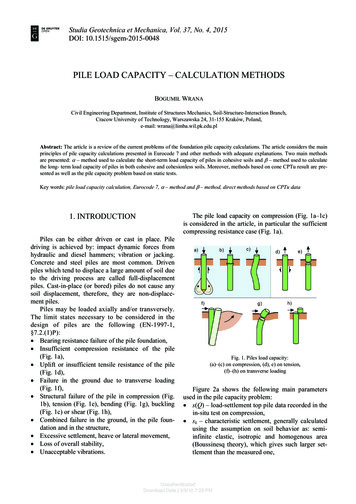
3.7from e.q. 3.2 we see thatMZ MZ .3.8applying the same principle, in the x direction we get equivalent equation.If we assume that themoment MX and MZ generated by the force Q are acting on a group of pile, then the sum offorces acting on a single pile will be as follows: 3.9if we dividing each term by the cross-sectional area of the pile, A, we can establish the workingstream σ :Example 3.1As shown in figure 3.2, A group of Vertical piles are subjected to an eccentric force Q,magnitude of 2600kN. Determine the maximum and the minimum forces on the piles. Q islocated 0.2 m from the x-axis and 0.15 m from the z-axis.
Figure 3-3 Worked exampleSolution1. Calculate Moment generated by the eccentric forceMx 2600 (0.2) 520 KNMz 2600 (0.15) 390 KN2.Calculate vertical load per pile: 2600/12 217 kNDIST.PILErximr2xirzir2ziMXMZ2mm2mkNkNm
.900.450.203*2520390 6.48Q/nPILEa1Mxrzi/ r2zi12.153Mzrxi/ r2xiPikNkN(520 rzi)/12.153(390* rxi)/ 6.482175854217-58-54 105** Minimum load 105 KN, carried by pilea1a21954217-19-54 144a31954217 19-54 182a45854217 58-54 221b1580217-58-00 157b2190217-19-00 157b3190217 19-00 236b4580217 58-00 275c15854217 58-54 221c21954217-19 54 252c31954217 19 54 290c45854217 58 54 329*** Maximum load 329 KN, carried bypile c4Example 3.2A pile trestle shown on figure 3-3 consists of four vertical piles surmounted by a1.2m thick pile cap. It carries a horizontal load applied to the surface of the capof 400kN. The only vertical load exerted on the pile group is the weight of thepile cup. Determine the loads on the piles.
Figure 3-4 Example 3.2Solution:1. Determine the magnitude of the vertical force: For a pile cape 4.000m square, weight of pilecap is:4 x 4 x 12 x 4 461kN vertical load 461kN2. Determine the location of the N.A. for the vertical piles:3 . resultant of vertical load and horizontal load cuts the underside of the pile cup at a point1.06m from N.A. pile group. This can be achieved graphically. E.g. On a millimetre paper, inscale, draw the pile cup. Taking the top of the pile cup draw the vertical component downwardas shown in figure 2-3 then taking the tip of the vertical component as reference point draw thehorizontal component perpendicular to the vertical component. By joining the two componentsestablish the resultant force R. Measure the distance from the N.A to the cutting point of R atthe underside of the pile cup.4. Using the following formula, calculate the load on each pile:
202kN ma
this web-version that can be accessed via internet or intranet and can be used as a supplementary self-assisting students guide. STRUCTURE OF THE GUIDE Introduction to pile foundations Pile foundation design Load on piles Single pile design Pile group design Installation-test-and factor of safety Pile installation methods Test piles Factors of .

![20160924 修正版 System Keisoku ENG.ppt [互換モード]](/img/4/companyprofileinenglish.jpg)