Transcription
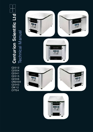
Technical ManualCenturion Scientific LtdC2012C2004C2041C2015C2006CR2000C2043CW12CYT04
ContentsHelp page2Error and Test Codes3Circuit board4-5Electric Motor and Tachometer6-7Inverter8-9Main’s inlet and EMC filter10-11Lid Lock12Lid Seal13Gas strut (if fitted)14Imbalance detector15Circuit diagram16-19Parts list20-22 Please note pictures are for illustration purposes only Wire colours may varyCenturion Scientific Ltd
FixingsSide fixing screwsSide fixing screwsBA M4 X 12mm (4)CWithin hinged blackcoverAB M4 X 12mm (6)Dome head screwC M4 X 10mm (6)Counter sunkscrewLid Latch fixingsGas strut fixingsLid Latch fixingsD M6 dome nutE Lid lock latchDGas strut fixingsFGEF Gas strut lowerfastening clipG 6mm opening Gasstrut clevis clip(Top)Motor top plate fixing screwsMotor top platefixing screwsHH Emergency lid release plug(Black)Located to under side ofbaseIIRotor recognitionsensorM3 X 6mmCounter sunkscrewIM5 x 10Pan head withspring washerJ1
Help pageTacho on display means the motor has not seen a revolutionin 4 seconds. IT DOES NOT ALWAYS MEAN A TACHOMETERFAILURE. The use of tubes that are too long, or an obstructioncan cause the same effect. Alternatively, a motor invertor orboard failure meaning no power or revolution to the motor.Check the tubes and rotation first with an empty rotor. If itturns, then tubes are the problem. If it doesn’t turn, then thiswould be the motor, invertor to the mains is at fault.Always check that the display is lit, and the lid locks are fine.Check tachometer using Test 13. See page 3.Bal on display means an imbalance has occurred If this baldisplay does not clear on restarting, then the detector or it’s5 volt lines are broken. Check back to the circuit board. Thedetector is wired closed. A break in the 5 volt line will showthis display. See page 16.ALWAYS WEIGH AND OPPOSE SAMPLES IN AN EVENFASHION IN THE ROTOR. This ensures a long life and goodseparations.Lid on display means the lid is not closed properly. Push downhard on both edges of front section of lid.It is imperative that you use a good strong work surface forany centrifuge to optimise separation and reduce noise.Recomendations lid adjustment.Centralise using not under lid latch2Centurion Scientific Ltd
Codes shown on theLED DisplayUUAlt- Wait 5 seconds press Lid open againOPEn - You may now open the LidtAcho? - Check that your tubes are not toolong and fouling the lid or anything else isstopping rotation of the rotor.Lid? - Close the LidbAL? - An imbalance has occurred Please check the tubes are diagonally opposite andof the same weight.Check if the tubes are broken If so use better quality, or if glass reduce the speed to themanufacturers recommended G force.NOTE: If drucH or drIuE (drive) show please Contact Service Department, or refer to technical manual.CR 2000 model onlyyrotor? - The sensor has found the speed to be incorrect to the rotorssettings, it will have readjusted. Please recheck your speed and tryagain.If this continues contact the service department.rrEc ?- A problem with the sensor or inverter has occurred pleasecontact the service department.Test tESt Routine(all C series LED models)This allows you to turn on or off the buzzer and to check the sensors for,Tachometer, Rotor recognition, Lid open & Imbalance detector.See 23 Each go 0/1 as you turn rotor or operate Imbalance detector or shut lidlid.Centrifuge lid in open position. Mains off at rear switch.Press function (keep held down) whilst turning on at rear switch. When test shows release function button.Press time up arrow See numbers in time display go to . 18Buzzer off or on (0/1) . 18Set speed Rpm digits in 10 or 100 Rpm steps . 19EEtE St - E prom check Press Speed up arrow . Number not shown8888 88 - LED display check increment speed up arrow . Number not shownRotor rec TachoLid open Imbalance . 24Turn rotor Turn rotor Close lid Push rotor to one side . Display changes from 0 to 1Bu2t St - Buzzer test press speed up arrow . Number not shownDo9t St - Watchdog test Press speed up arrow. HELL 0 - (Hello) should display, then back to normal.3
Circuit board replacement - LEDPart number: 3022301 Subject to change R&D For illustration purposes only4Centurion Scientific Ltd
Dismantling sequence prior to replacementNOTE: Remove mains electricity power cord first1 Un-hinge black cap. Unscrew and remove 4 screws to front panel.2 Remove all screws to composite sides (at rear). Both sides should now beremoved. Store safely with consequent screws,washers and hinge caps (black).3 Remove bottom clip to Gas Struts and pull off the bracket.4 Remove black metal top cover with lid as follows.5 Remove all M4 screws to rear, not around mains inlet. Then remove 2 countersunk screws near front lid lock holes.6 Pull off black top cover and lid. Place carefully to one side.7 Unscrew and remove M4 screws underneath front panel, by pulling centrifugeforward over work surface. Not too far!8 Unplug 10 way connector to circuit board.9 Remove complete panel to another area.10 Unplug 4 way connector to board and blue Ethernet Cable.11 To remove circuit board unscrew all M3 pillar nuts to rear.12 Slide off the M3 threaded rods carefully.Replacement is reversal of above. Do not over tighten the pillar nuts.Make sure rubber pads are fitted to the A6 switches before fitting.5
Motor replacementPart number: 1189001(C2012, C2015, C2004, C2006,CR2000, Pro-Sep E, Pro-SepS, Pro-Vet HE, Pro-Vet Multi,CR2000 with rotor recognition)Part number: 1188001(C2041)Motor with cover and rotorrecognitionDismantling sequence prior to replacement.NOTE: Remove mains electricity power cord first1 Un-hinge black cap. Unscrew and remove 4 screws to front panel.2 Remove all screws to composite sides (at rear). Both sides should now beremoved. Store safely with consequent screws,washers and hinge caps(black).3 Remove bottom clip to Gas strut(s) and pull off the bracket.4 Remove black metal top cover with lid as follows.5 Remove all M4 screws to rear, not around mains inlet. Then remove 2 countersunk screws near front lid lock holes.6 Pull off black top cover and lid. Place carefully to one side.7 Remove stainless steel top cover to motor top, by removing 4 M5 screws.8 Pull bowl up and out. Note under seal to bowl top position.9 Unscrew with spanner or box key All 3 M8 nuts to motor chassis. Place to oneside.10 Unplug motor connection to mains in supply . Turn over motor to view bottom andremove 12 way cable plug to circuit board socket.6Centurion Scientific Ltd
Motor with cover and rotorrecognition senor screwsremovedLay motor at an angle and fit the mainsconnector, then fit the 12 way smallconnector to bottom circuit board.Fit the 3 way connector if so fitted.Place motor over Anti vibration mountsand add spring washer’s and M8 nuts.Tighten carefully byholding AV mountsto prevent any twist in the mounts. Notrecommended.Push rotor recognition sensor throughhole in rubber boot if fitted the place bowlover motor. Make sure seal to barrierring is fitted correctly (opening to centrerear for ventilation). Check free turning ofmotor and all satisfactory before refittingtop and sides . As reversible of above.Tachometer The tachometer is ahorseshoe LED type, 5volt, sensing dark and lightcurrent off the butterflyinterrupter.NO ADJUSTMENT necessary,apart from fix to array. Keep arrayclean for optimum use.7
Inverter replacementPart number: 6002001Dismantling sequence prior toreplacementNOTE: Remove mains electricitypower cord first1 Un-hinge black cap. Unscrew and remove 4screws to front panel.2 Remove all screws to composite sides(at rear). Both sides should now beremoved. Store safely with consequentscrews,washers and hinge caps(black).3 Remove bottom clip to Gas Struts and pulloff the bracket.4 Remove black metal top cover with lid asfollows.5 Remove all M4 screws to rear, not aroundmains inlet. Then remove 2 counter sunkscrews near front lid lock holes.6 Pull off black top cover and lid. Placecarefully to one side.7 Remove all wiring to inverter.8 Unscrew and remove all 4 M4 screws tobase of Inverter.Replacement is reversal of above.The replacement will be programmed for use.Do not change any parameters8Centurion Scientific Ltd
Wiring to induction motorfrom inverterBlack to UBrown or Red to VBlue to WGrey to PE (Next to W)Grey to B7(Above does not matterwhich direction)PR to T1Wiring to inverter from mainsfilterRed/ Brown to L1Blue/ Black to L2-NEarth to Tag9
Mains inlet & filter replacementDismantling sequence prior to replacementNOTE: Remove mains electricity power cord firstMains inlet is double fused, with an IEC socket for power source. It is held in placewith 2 X M3 screws. Fuses are 5X20mm, 6.3 (TA) Slow blow only.10Centurion Scientific Ltd
Part number: 2000013Part number: 20000731 Un-hinge black cap. Unscrew and remove 4 screws to front panel.2 Remove all screws to composite sides (at rear). Both sides should now beremoved. Store safely with consequent screws,washers and hinge caps (black).3 Remove bottom clip to Gas Struts and pull off the bracket.4 Remove black metal top cover with lid as follows5 Remove all M4 screws to rear. Not around mains inlet. Then remove 2 countersunk screws near front lid lock holes.6 Pull off black top cover and lid. Place carefully to one side.7 On rear panel unscrew 2 M3 countersunk screws holding mains inlet in place.8 Disconnect tab connectors to filter and tab connectors to inverter.9 Remove filter by unscrewing M4 screwsReplacement is reversal of above.Note: EMC filter must be used to comply with EMC Regulations.11
Lid lock replacement - LEDPart number: 6844000A12Centurion Scientific Ltd
Dismantling sequence prior to replacement.NOTE: Remove mains electricity power cord first1 Un-hinge black cap. Unscrew and remove 4 screws to front panel.2Remove all screws to composite sides (at rear) Both sides should now beremoved. Store safely with consequent screws,washers and hinge caps(black).3 Remove bottom clip to Gas Struts and pull off the bracket.4 Remove black metal top cover with lid as follows.5 Remove all M4 screws to rear, not around mains inlet. Then remove 2 countersunk screws near front lid lock holes.6 Pull off black top cover and lid. Place carefully to one side.7 Unscrew and remove M4 screws underneath front panel, by pulling centrifugeforward over work surface. Not too far!8 Unplug 10 way connector to circuit board.9 Remove complete panel to another area.10 Unplug 4 way connector to board.11 To remove Lid locks unscrew 2 x M6 Countersunk screws. (See A page 14)Replacement is reversal of above.Lid lock is powered via 12 volts through capacitor charging.AdjustmentLatches (in lid) need to be centralised to lid lock opening. Adjust with under nuts13
Lid seal replacementPart number: 4171001(C2004, C2006, CR2000)Pro-Vet multi, Pro-Sep SCW12, CYTO4Part number: 4151001(C2041)Part number: 4191001(C2012, C2015, Pro-Vet HE,Pro-Sep E)Dismantling sequence prior to replacement.NOTE: Open centrifuge lid, then turn off and remove mainselectricity power cord.Remove old lid seal by gently pulling towards centre of bowl.Replace by pushing u section into top wall all the way round.NOTE the seal MUST be fitted correctly or damage may be caused if it releases frommetalwork.14Centurion Scientific Ltd
Gas strut replacementPart number: 2172801(C2004, C2006, CR2000)Pro-Vet multi, Pro-Sep SCW12, CYTO4Part number: 2152801(C2041)Dismantling sequenceprior to replacementNOTE: Remove mainselectricity power cordfirst1 Un hinge black cap. Unscrewand remove 4 screws to frontpanel2 Remove all screws to compositesides (at rear sides) Both sidesshould now be removed .Storesafely with consequent screws,washers and hinge caps(black)3 Remove bottom clip to GasStruts and pull off the bracket4 Unscrew other end of gas strutfrom Lid5 Replace and reverse procedureof above15
Imbalance detectorPart number: 2000104This detector is wired normally closed, and uses a 5 volt DC supply from the circuitboard. Any interruption in this supply line will mean that Bal will show on the display.Dismantling sequence prior to replacementNOTE: Remove mains electricity power cord first1 Un-hinge black cap. Unscrew and remove 4 screws to front panel.2 Remove all screws to composite sides (at rear). Both sides should now beremoved. Store safely with consequent screws,washers and hinge caps (black).3 Remove bottom clip to Gas Struts and pull off the bracket.4 Remove black metal top cover with lid as follows.5 Remove all M4 screws to rear, not around mains inlet. Then remove 2 countersunk screws near front lid lock holes.6 Pull off black top cover and lid. Place carefully to one side.7 Remove stainless steel top cover to motor top, by removing 4 M5 screws.8 Pull bowl up and out . Note under seal to bowl top position.9 Unscrew 2 M4 screws, unplug socket to circuit board, then remove imbalancedetector.10 Replace with new detector, and replug into circuit board.11 Adjust end shaft of detector to within 2-5mm of motor chassis.Note: check adjustment by using Test 13. Push motor to one side to check correctlyinterrupting detector.16Centurion Scientific Ltd
17 * ( % ( % ' ! ' % '% !% ' ( ' ( ! ( ' 8%) # % #% ## ! ' '-./,210/:-. ! ( /: /,210/:210/.,.97/: 2 1 0 / . - , .97 5 # 5 #5 ## # 5# # 5# 5 5" # # ' ' 8 5/:01/2 8 (8## %) #) 8 85 8 8# " # 5 ' '' ' # 5' '5 5' ' # ! .- (/ 55 0# 5 # # 5' '' 2' ' # & % ## #' ' ' ' ' #' ,, ! !1.-/: ' ' 0/: 5 # 5 # 5 # 5 # 5 # 5 #' '/2 " " " " " "01% . (/2-& % 8% 1,, ! ! /: .- 8 ( !& ! ! ! % #%! % ! % ! # 5 # ## ## ## ## ## ## ### ! ! ! ! ! ! # 5 ( ( ! & # 5' ' ' ' ' ' '# # 8 8 # 5# 5# & 85 # # # 460 ,48 .3 9. 7-0; ' ! & , 0 &%&% !) @%) #) & #0?4 498 8 8## 8% 8 (8 (" # # ' ' 96 &HQWULIXJH &RQWURO 3&% 4@0 %4 60" ! ' ' 8 8 ' ' 08 8 ' " ! 8 '48 &!;48 0/ & ( ( #! # % # ! & #! ! # ! & #! ! # 8 # 8# 5 ' ' !% '# # '# # ! & #! # ! & #! # #! # #! # #! # #! # ! & #! , ! # #! ! # ! & #! , ! # #! ! # #! % ! # '# #% #! ! (# # #! ! # # % ! # #! ! # % ! # % ! # #! ! # % ! # #! ! # #! ! # #! ! # #! ! # #! ! # #! ! # #! ! # #! ! # & ! !(# ! ! ' ' ! % .97 , - . / 0 1 2 /: .97,./012/: ' ' ' '# ' ! ' # .97 , - . / 0 1 2 /: .97,./012/: ' ' '' ':: 300 91 2WKHOOR 'ULYH:DWHUORRYLOOH DQWV 32 / (QJODQG#
18Centurion Scientific Ltd " 5-, & 1 " 5 - , & - 1 ,, "1 - & 5 , 5 - " " 5 " 8 11 18 2 2 2 "2 52 -2 , 1 & 2 2 2 12 2 "2 52 -: ) 2 ) 2 ) 2 )12 ) 2 )"2 )52 ),2 ) ) "2 ) 52 ) -2 ) - ( % ( ' ( - 5% -1 5 A) " & ( ' F * &- ( ' %6. -%- &&) 15 & 1 5 &)& " ,& %& " & && C15&) && 6 5 1- ) 1 : @ &&1% 7, 1" % 7 5 A 1 @ 1- %"1&1 1%&"1&1 1%1) 50 5 - 6! && & & 3? ? 3 ):1 : 3 -C * ' ) 4 &0 C &-& ) 4 &0 C &-& ) 4 &0 C &-& ) 4 &0 C &-& ) 4 &0 C &-& ) 4 &0 C &-& ) 4 &0 C &-& ) 4 &0 C &-& ) 4 &0 C &-& ) 4 &0 C &-& ' 5 &0 "; 6' * 3 && 6 & ) 0 B ) 2 ) 2 ) 12 ) "2 ) 52 ) 2 ) 2 ) 2 ) 12 ) 2 ) "2 ) 52 ) -2 ) ,2 )1&2 )1 2 )1 ) ,2 ) 2 ) ,11 ) ( 0 # &0- ( % ) 1- 3 # # (- 3 3 1 '' )( 3 G (- ( 3? # @ ( 3 ( %-6 * &0 ; * 0- # 6 * &0 ; & ) 4 &0 C &-& ) &2 ) &2 ) &( &&# 4 &"& ) 3 9 0 &&# 6 * &0 ; 1 * 6 1,78% 3 3 3 3 % &# &4 /5) &-& 3 3 % &# &4 /5) &-& 3 3 % &# 4 /5) &-& 3 3 % # &4 / ) & & 3 ' 3 # F7% &4 & 3 3 % &# &4 /5) &" && && 3 ' 3 # F7% &4 & % &" !! "#)-) 1) ) ) ) ' 2 ' 2 ' 8 8 8"81: : :1 / 2 2 12 2 "2 52 - 2 "2 52 ,2 & - & 12 2 2 , %"1&1 1%& 3 7 5 A 1 @ 3? * 3? * E 6 . - 5% -1 5 A) " & " ,& 6. -%- %& " & && C " & %' 5 3 1- ) 1 : @ &&1% 7, 1" % 7 7 3 3? 3 3? ( % 1- "1&1 1%1 3 7 ./ && "/ 0 ) ./ && "/ 0 % &" ? ) G 3 ) G 3 ' ( ' - "' &,1,,5' 1, & ' & 55,1 1& % ,5&% DD %' ' 51& ,' & - "' "1 &5' , ' 1 -' 1"-55"' 1", ) * %& &' -- 11' --1,&' , & "&' 1 5 &5' 1 1" ' 1 1""1' 1 1"" ' 1 1""&' 1" 5 ' -- "1' 11" ' 11" ) * % ,- Circuit board replacement - LED
19
Circuit board replacement - LED20Centurion Scientific Ltd
Spare Parts listFor models:C2004C2006CR2000CYT04CW12Pro-Vet MultiPro-Sep SPart NumberDescription1189001Hanning Small motor1185201Anti vibration mounts blue dot (C2006 only)1184205Anti vibration mounts Robush (All others)1080001Complete Tacho & Imbalance Assembly2000013Mains inlet Switch complete2000171EMC filter complete with wiring6002001Inverter Emerson 3.7 KV6100086Ethernet Cable3022301LED Circuit board VS12236844000Lid lock 12 volt Rharbach4071021Bowl complete – stainless steel4171001Bowl seal (top)* No discount on these items21
Spare Parts listFor models:C2012C2015Pro-Vet HEPro-Set EPart NumberDescription1189001Hanning Small motor1184203Anti vibration mounts Orange108001Complete Tacho & Imbalance assembly2000013Mains inlet Switch complete2000171EMC filter complete with wiring6002001Inverter Emerson 3.7KV6100086Ethernet Cable3022301LED Circuit board VS12236844000Lid lock 12 volt Rharbach4091021Bowl complete – Stainless steel4191001Bowl seal (top)* No discount on these items22Centurion Scientific Ltd
Spare Parts listFor models:C2041Part NumberDescription1188001Hanning large Motor1184202Anti Vibration mounts Large1080001Complete Tacho & Imbalance assembly2000013Mains inlet switch complete2000171EMC Filter complete with wiring6002001Inverter Emerson 3.7KV6100086Ethernet Cable3022301LED Circuit board VS12236844000Lid lock 12 volt Rharbach4051021Bowl complete – Stainless steel4151001Bowl seal (top)* No discount on these items23
User’s Notes24Centurion Scientific Ltd
25
Established in the marketplace since 1989Distributed byManufactured by:Centurion Scientific Ltdemail: fic.co.uk
6 Centurion Scientifi c Ltd Motor replacement Part number: 1189001 (C2012, C2015, C2004, C2006, CR2000, Pro-Sep E, Pro-Sep S, Pro-Vet HE, Pro-Vet Multi, CR2000 with rotor recognition) Part number: 1188001 (C2041) Motor with cover and rotor recognition Dismantling sequence prior to replacement. NOTE: Remove mains electricity power cord fi rst