Transcription
WBII-SER Rev HService ManualModels: 51 - 211 WARNINGThis manual must only be usedby a qualified heating installer/ service technician. Readall instructions, includingthis manual and the KnightWall Mount Installation andOperation Manual, beforeinstalling. Perform steps inthe order given. Failure tocomply could result in severepersonal injury, death, orsubstantial property damage.Save this manual for future reference.
ContentsCONTENTS. 2Hazard Definitions . 2PLEASE READ BEFORE PROCEEDING . 3Handling Ceramic Fiber Materials . 3When servicing boiler . 4Boiler operation. 4Boiler water . 4Freeze protection fluids . 4WHAT IS IN THIS MANUAL . 51. SERVICENear Boiler Piping . 6The Knight Wall Mount Display . 7Control Inputs . 8Control Outputs. 9General Operation . 10Sequence of Operation . 11-12Display Panel Menu Access . 13Display Panel Parameter Access . 14Parameter Table. 15-18Viewable and Changeable Control Parameters . 19-272. MAINTENANCEMaintenance and Annual Startup . 28-323. TROUBLESHOOTINGBefore Troubleshooting . 33Check Control Module Fuses . 33Table 3-1 - Troubleshooting Chart - No Display . 34Checking Temperature Sensors . 35Table 3-3 - Troubleshooting Chart - Noisy System . 36Table 3-4 - Troubleshooting Chart - Fault Messages . 37-45Combustion Analysis Procedure . 46Table 3-5 - Troubleshooting Chart - Combustion Levels 46Table 3-6 - Flue Products . 46Gas Valve Adjustment Procedure . 47Revision Notes . Back CoverHazard definitionsThe following defined terms are used throughout this manual to bring attention to the presence of hazards of various risk levelsor to important information concerning the life of the product. DANGERDANGER indicates an imminently hazardous situation which, if not avoided, will result in death or seriousinjury.WARNING indicates a potentially hazardous situation which, if not avoided, could result in death or serious WARNING injury.CAUTION indicates a potentially hazardous situation which, if not avoided, may result in minor or moderate CAUTION injury.CAUTIONCAUTION used without the safety alert symbol indicates a potentially hazardous situation which, if notavoided, may result in property damage.NOTICENOTICE indicates special instructions on installation, operation, or maintenance that are important but notrelated to personal injury or property damage.2
Service ManualPlease read before proceeding WARNINGInstaller – Read all instructions,including this manual and the KnightWall Mount Installation and OperationManual, before installing. Perform stepsin the order given.NOTICEUser – This manual is for use only bya qualified heating installer/servicetechnician. Refer to the Knight WallMount User’s Information Manual foryour reference.Have this boiler serviced/inspected bya qualified service technician at leastannually.When calling or writing about the boiler– Please have the boiler model and serialnumber from the boiler rating plate.Consider piping and installation whendetermining boiler location (see the KnightWall Mount Installation and OperationManual).Any claims for damage or shortagein shipment must be filed immediatelyagainst the transportation company by theconsignee.Failure to comply with the above couldresult in severe personal injury, death orsubstantial property damage.Handling ceramic fiber materialsREMOVAL OF COMBUSTION CHAMBER LINING WARNINGThe combustion chamber insulation in this appliance contains ceramic fiber material. Ceramic fibers canbe converted to cristobalite in very high temperature applications. The International Agency for Researchon Cancer (IARC) has concluded, “Crystalline silica in the form of quartz or cristobalite from occupationalsources is carcinogenic to humans (Group 1).” Normal operating temperatures in this appliance are belowthe level to convert ceramic fibers to cristobalite. Abnormal operating conditions would have to be createdto convert the ceramic fibers in this appliance to cristobalite.The ceramic fiber material used in this appliance is an irritant; when handling or replacing the ceramicmaterials it is advisable that the installer follow these safety guidelines. Avoid breathing dust and contact with skin and eyes. Use NIOSH certified dust respirator (N95). This type of respirator is based on the OSHArequirements for cristobalite at the time this document was written. Other types of respirators maybe needed depending on the job site conditions. Current NIOSH recommendations can be found onthe NIOSH website at http://www.cdc.gov/niosh/homepage.html. NIOSH approved respirators,manufacturers, and phone numbers are also listed on this website. Wear long-sleeved, loose fitting clothing, gloves, and eye protection. Apply enough water to the combustion chamber lining to prevent airborne dust. Remove the combustion chamber lining from the appliance and place it in a plastic bag for disposal. Wash potentially contaminated clothes separately from other clothing.thoroughly.Rinse clothes washerNIOSH stated First Aid. Eye: Irrigate immediately. Breathing: Fresh air.3
Service ManualPlease read before proceedingWhen servicing boiler – To avoid electric shock, disconnect electrical supplybefore performing maintenance. To avoid severe burns, allow boiler to cool beforeperforming maintenance.Boiler operation – Do not block flow of combustion or ventilation air tothe boiler. Should overheating occur or gas supply fail to shut off,do not turn off or disconnect electrical supply tocirculator. Instead, shut off the gas supply at a locationexternal to the appliance. Do not use this boiler if any part has been under water.The possible damage to a flooded appliance can beextensive and present numerous safety hazards. Anyappliance that has been under water must be replaced.Boiler water – Thoroughly flush the system (without boilerconnected) to remove sediment. The high-efficiencyheat exchanger can be damaged by build-up orcorrosion due to sediment. Do not use petroleum-based cleaning or sealingcompounds in the boiler system. Gaskets and seals inthe system may be damaged. This can result insubstantial property damage. Do not use “homemade cures” or “boiler patentmedicines”. Serious damage to the boiler, personnel,and/or property may result. Continual fresh make-up water will reduce boiler life.Mineral buildup in the heat exchanger reduces heattransfer, overheats the stainless steel heat exchanger, andcauses failure. Addition of oxygen carried in by makeupwater can cause internal corrosion. Leaks in boilerpiping must be repaired at once to prevent theintroduction of makeup water.Freeze protection fluids – NEVER use automotive antifreeze. Use only inhibitedpropylene glycol solutions which are specificallyformulated for hydronic systems. Ethylene glycol istoxic and can attack gaskets and seals used in hydronicsystems.4
Service ManualWhat is in this manual?ServiceMaintenanceNear boiler piping Service and maintenance schedules Address reported problems Inspect boiler area and boiler interior Clean condensate trap Check all piping for leaks Check air openings Flue vent system and air piping Check water system Check expansion tank Check boiler relief valve Inspect ignition electrode Check ignition ground wiring Check all boiler wiring Check control settings Perform start-up and checks Check burner flame Check flame signal Check flue gas temperature General maintenance Review with owner Cleaning boiler heat exchanger Oiled bearing circulators Typical system componentsThe Knight wall mount boiler display Display panel readout, buttons and their functionsControl module inputs Control module inputs and optionsControl module outputs Control module outputs and optionsGeneral How the boiler operates How the control module operates Access modes -- user and installer Sequence of operation -- Domestic Hot Water(DHW)/space heatingControl panel menu access Accessing programming mode and locating menus(See separate guide covering the PC interface.)Control panel parameter access Accessing and changing parameters from the display panelQuick start information -- parametertable An index of available adjustments and readouts, where toaccess them and where to find detailed information.Knight wall mount boiler operationTroubleshooting Troubleshooting table - No display Checking temperature sensors Sensor tables Troubleshooting table - Fault messages displayed onboiler interface Combustion analysis procedure Gas valve adjustment procedure A: General B: Temperature Setting C: Data Logging D: Functions E: DHW Settings F: Outdoor Reset G: Anti-cycling H: Control Modes I: Circulation Pumps J: Building Management System (BMS) K: Service Notification5
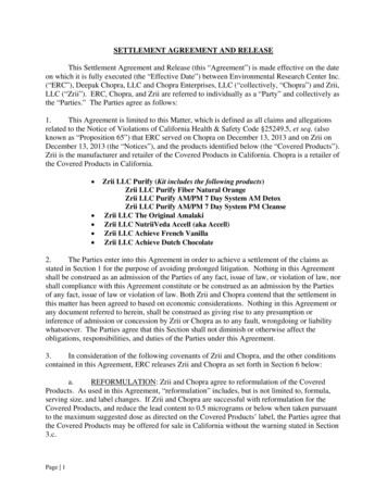
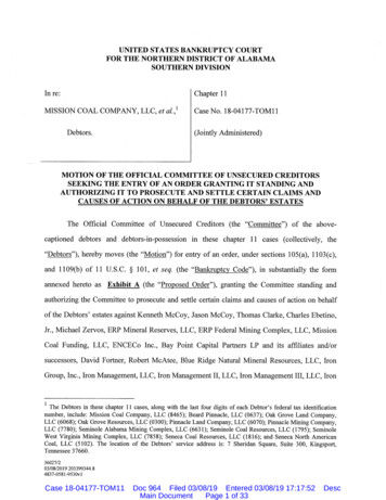
Service Manual1ServiceNear boiler pipingThis piping reference is included to specify the Near Boiler Piping specific to the Knight wall mount boiler. This piping schemeis important for proper operation of the SMART SYSTEM control. See the Knight Wall Mount Installation and OperationManual for more detailed piping diagrams.VENT AIROMFRCONDENSATEDRAINTODOMESTICHOT STRAINER(RECOMMENDED)MTOSTSYEMSYSTEMPUMPTO FLOORDRAINESTSYINDIRECTDOMESTICHOT WATERTANKEXPANSION TANK
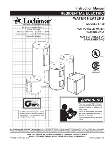
Service Manual1Service(continued)The Knight wall mount displayNAVIGATION DIALThe information on the bottom of the display shows the functions of the two SELECT keys (on either corner), and theNAVIGATION dial (in the center):MENU Left SELECT KeySETPOINTS NAVIGATION Dial - Pressing DownSHDN Right SELECT Key7
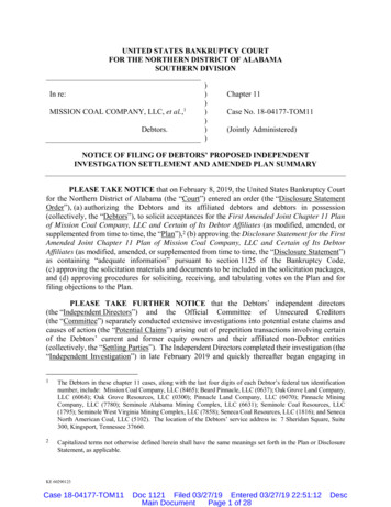
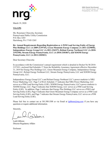
Service Manual1ServiceControl inputsSYSTEM PUMP SPEED CONTROLGAS PRESSURE SWITCHDHW THERMOSTATROOM THERMOSTAT /ZONE CONTROLFLOW SWITCHLOW VOLTAGECONNECTIONBOARDSYSTEM SENSOROUTDOOR SENSORBUILDING MANAGEMENTSYSTEMLOW WATER CUTOFFINLET TEMPERATURESENSOROUTLET TEMPERATURE /HIGH LIMIT SENSORFLUE GAS SENSORPRESSURE SWITCHFLAME SENSORBLOCKED DRAIN SWITCHDISPLAY PANELPC INTERFACE8SMART CONTROLMODULE
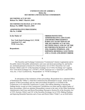
Service Manual1Service(continued)Control outputsALARM BELLLOW VOLTAGECONNECTIONBOARDAUX. DEVICE RELAYRUN TIME CONTACTSBUILDING MANAGEMENTSYSTEMBOILER PUMPSYSTEM PUMPDHW PUMPIGNITORBLOWERSMART CONTROLMODULEGAS VALVEDISPLAY PANELPC INTERFACE9
Service Manual1ServiceGeneral OperationHow the boiler operatesAccess modesThe Knight wall mount boiler uses an advanced stainless steelheat exchanger and an electronic control module that allowsfully condensing operation. The blower pulls in gas and airand pushes flue products out of the boiler through the heatexchanger and flue piping. The control module regulatesblower speed to control boiler firing rate. The gas valvesenses the amount of air flowing into the boiler and allowsonly the right amount of gas to flow.UserHow the control module operatesThe Knight wall mount control module receives input fromboiler sensors. The control module activates and controlsthe blower and gas valve to regulate heat input and switchesboiler, DHW and system pumps on and off as needed. Theuser/installer programs the module to meet system needs byadjusting control parameters. These parameters set operatingtemperatures and boiler operating modes. Boiler operationcan be based on boiler outlet water temperature, boiler returnwater temperature or system supply temperature, dependingon the parameter setting.The user can adjust space heating and tank target temperaturesby pressing the NAVIGATION dial when “ SETPOINTS” isflashing at the bottom of the display. The date and time, andthe temperature units can also be changed.InstallerMost parameters are available only to the installer, accessibleonly by entering the installer password, see the Knight WallMount Service Manual.Saving parameters (reference the Parameter Table Table 1-4 on pages 15 - 18 of this manual)NOTICEPlease note that the brackets ([]) denotescreen status.To save parameters and exit programming:Press the RIGHT SELECT [SAVE] key and then press theRIGHT SELECT [HOME] key.Sequence of operationTo enter a parameter and continue programming:Table 1-1 shows control module normal sequences ofoperation for space heating and DHW operation. Thecombined operation sequence is for a typical application,programmed to provide DHW priority.Press the RIGHT SELECT [SAVE] key 1 time to return to theparameter listings; press again to return to the menu listings.Remember to press the RIGHT SELECT [HOME] key whenfinished programming in order to save the changes made.10
Service Manual1Service(continued)Sequence of operationOPERATIONDISPLAY1. Upon a call for heat, the gas pressure switch(es) must be closed.2. Once the gas pressure switch(es) are closed, the control turnson the appropriate pumps (system and boiler pumps for spaceheating, DHW pump for DHW). The flow switch and/or LWCOmust close.3. The control turns on power to the louver relay. The louverproving switch, air pressure switch, and blocked drain switchmust close.4. The control starts the prepurge cycle by initiating the blower.5. The control starts the trial for ignition by firing the sparkelectrode and opening the gas valve.6. If flame is not detected after the sparking ends, the control willperform a postpurge, then start another prepurge cycle and try tolight the burner again. The control will perform a total of 4 attemptsbefore locking out.7. If flame is detected, it holds the firing rate steady for a fewseconds to let the flame stabilize, then it begins to modulate thefiring rate based on a set point or some other command (suchas a 0-10V BMS signal).11
Service Manual1ServiceSequence of operation(continued)OPERATION8. If the space heating call for heat is active, and the tank thermostator sensor starts a DHW call for heat, the boiler will switch to theDHW mode. If programmed for normal DHW operation (not asa zone), the DHW pump will turn on first, then the boiler pumpwill turn off (boiler and DHW pump operation briefly overlap toensure flow is maintained through the unit). This will divert theboiler’s outlet water from the heating system and send it to thetank coil instead. The control will then modulate to maintain theoutlet temperature to the DHW boiler set point.9. If the boiler is not part of a Cascade, and both the space heatingand DHW calls for heat remain active long enough, the boiler willswitch back and forth between the two heating modes until oneof them is satisfied.10. Once both calls for heat are satisfied, the control will turn offthe burner. The blower will continue to run during the postpurgeperiod.11. Any pumps that are running will continue to run for theirrespective pump delay times before turning off, unlessprogrammed to remain on continuously. A 60 second anti-cycleperiod will start, which will delay any new call for heat until ittimes out.12. In Standby, ready to start a new cycle.12DISPLAY
Service Manual1Service(continued)Display panel menu accessTable 1-2 Use this procedure to access menus from the display ISPLAYPress the RIGHT SELECT soft key [SHDN].Press the LEFT SELECT soft key [YES].Press and hold the LEFT SELECT soft key [MENU]for five (5) seconds.Rotate the NAVIGATION dial clockwise until 5 isdisplayed (first digit on the left).Press the NAVIGATION dial to select the next digit.Rotate the NAVIGATION dial clockwise until 3 isshown in the display.Press the NAVIGATION dial 2 times to move to the lastdigit. Rotate the NAVIGATION dial counterclockwiseuntil 9 is displayed.[SAVE]Press the RIGHT SELECT soft key [SAVE].Rotate the NAVIGATION dial counterclockwise toselect a category.13
Service Manual1ServiceDisplay panel parameter accessTable 1-3 This is a typical example of accessing a parameter, shown for parameter Temperature Settings, MINSH SetptBUTTONSCREENSTATUSOPERATIONDISPLAYThis example shows how to access parameter Temperature Settings. The first display shown is at the beginningof the menu listings, after entering the installer access code.Rotate the NAVIGATION dial counterclockwise untilthe arrow ( ) is next to TEMPERATURE SETTINGS.Press the NAVIGATION dial one time.Rotate the NAVIGATION dial counterclockwise untilthe arrow ( ) is next to MIN SETPT.Press the NAVIGATION dial one time.Rotate the NAVIGATION dial to the desiredtemperature.[SAVE]Press the RIGHT SELECT soft key [SAVE] one time.[EXIT]Press the LEFT SELECT soft key [EXIT] if all desiredchanges have been made.[HOME]14Press the LEFT SELECT soft key [HOME].
Service Manual1Service(continued)Parameter tableTable 1-4 This table lists SMART SYSTEM control module parameters and where to access themFUNCTIONSDATALOGGINGTEMPERATURE SETTINGSGENERALMenuDescriptionUser AccessSeePage Display ModifyInstaller AccessDisplayModifyTime and Date19YesYesYesYesSoftware Version (read only)19NoNoYesNoTemperature Units (ºC/ºF)19YesYesYesYesSH Night Setback Offset19NoNoYesYesSH Night Setback On Times19NoNoYesYesSH Night Setback Off Times19NoNoYesYesDHW Night Setback Offset19NoNoYesYesDHW Night Setback On Times19NoNoYesYesDHW Night Setback Off Times19NoNoYesYesDisplay Timeout20NoNoYesYesSH1 Set Point20YesYesNoNoMinimum SH Set Point20NoNoYesYesMaximum SH Set Point20NoNoYesYesSH1 Offset20NoNoYesYesSH1 Differential20NoNoYesYesSH2 Set Point20YesYesNoNoSH2 Offset20NoNoYesYesSH2 Differential20NoNoYesYesSH3 Set Point20YesYesNoNoSH3 Offset20NoNoYesYesSH3 Differential20NoNoYesYes3-Way Valve Time20NoNoYesYesReset Log Errors20NoNoYesYesService Mode Delay20NoNoYesYesFreeze Protection Pump On20NoNoYesYesFreeze Protection Burner On20NoNoYesYesFreeze Protection Burner Differential20NoNoYesYes15
Service Manual1ServiceParameter tableTable 1-4 (continued from previous page) This table lists SMART SYSTEM control module parameters and whereto access themOUTDOOR RESETDHW SETTINGSMenu16DescriptionUser AccessSeePage Display ModifyInstaller AccessDisplayModifyDHW Boiler Set Point21NoNoYesYesTank Set Point21YesYesYesYesTank Set Point Differential21NoNoYesYesDHW Boiler Offset21NoNoYesYesDHW Boiler Differential21NoNoYesYesSH/DHW Switching Time21NoNoYesYesDHW/SH Switching Time21NoNoYesYesTank Minimum Set Point21NoNoYesYesTank Maximum Set Point21NoNoYesYesDHW Type21NoNoYesYesFan Speed Limiting for DHW21NoNoYesYesOutdoor 1 Low22NoNoYesYesOutdoor 1 High22NoNoYesYesSet Point 1 at Low Outdoor Temp 122NoNoYesYesSet Point 1 at High Outdoor Temp 122NoNoYesYesOutdoor Air Shutdown SH122NoNoYesYesOutdoor Air Shutdown Differential SH123NoNoYesYesShift Reset Curve SH123NoNoYesYesOutdoor 2 Low22NoNoYesYesOutdoor 2 High22NoNoYesYesSet Point 2 at Low Outdoor Temp 222NoNoYesYesSet Point 2 at High Outdoor Temp 222NoNoYesYesOutdoor Air Shutdown SH222NoNoYesYesOutdoor Air Shutdown Differential SH223NoNoYesYesShift Reset Curve SH223NoNoYesYesOutdoor 3 Low22NoNoYesYesOutdoor 3 High22NoNoYesYesSet Point 3 at Low Outdoor Temp 322NoNoYesYesSet Point 3 at High Outdoor Temp 322NoNoYesYesOutdoor Air Shutdown SH322NoNoYesYesOutdoor Air Shutdown Differential SH323NoNoYesYesShift Reset Curve SH323NoNoYesYes
Service Manual1Service(continued)Parameter tableTable 1-4 (continued from previous page) This table lists SMART SYSTEM control module parameters and whereto access themCIRCULATION PUMPSCONTROL MODESANTI-CYCLINGOUTDOORRESETMenuDescriptionUser AccessSeePage Display ModifyInstaller AccessDisplayModifyBoost Temperature23NoNoYesYesBoost Time23NoNoYesYesAnti-Cycling Time23NoNoYesYesAnti-Cycling Override Differential23NoNoYesYesRamp Delay23NoNoYesYesRamp Settings24NoNoYesYesControlling Sensor24NoNoYesYesBMS Tstat ModBus T/O25NoNoYesYesCascade Address25NoNoYesYesCascade Type25NoNoYesYesMax Cascade Set Point25NoNoYesYesCascade Offset25NoNoYesYesCascade Differential25NoNoYesYesMin On/Off Time25NoNoYesYesMin Next On Time25NoNoYesYesBoiler Size25NoNoYesYesSystem Pump Delay256NoNoYesYesBoiler Pump Delay26NoNoYesYesDHW Pump Delay26NoNoYesYesBoiler Pump Anti-Seize Delay26NoNoYesYesBoiler Pump Min Voltage26NoNoYesYesSystem Pump Type26NoNoYesYesDHW Pump Anti-Seize Delay26NoNoYesYesSystem Pump Anti-Seize Delay26NoNoYesYes17
Service Manual1ServiceParameter tableTable 1-4 (continued from previous page) This table lists SMART SYSTEM control module parameters and whereto access themSERVICENOTIFICATIONBMSMenu18DescriptionUser AccessSeePage Display ModifyInstaller AccessDisplayModifyBMS Type26NoNoYesYesVolts at Min26NoNoYesYesVolts at Max26NoNoYesYesRate at Min Volts26NoNoYesYesRate at Max Volts26NoNoYesYesSet Point at Min Volts27NoNoYesYesSet Point at Max Volts27NoNoYesYesOn Volts27NoNoYesYesOff Differential Volts27NoNoYesYesService Notification Months27NoNoYesYesService Notification Running Time27NoNoYesYesService Notification Cycles27NoNoYesYesReset Maintenance Reminder27NoNoYesYesService Name and Phone Number27NoNoYesYes
Service Manual1Service(continued)Viewable and changeable control parametersCAUTIONBefore changing parameters, note thesettings so that the unit can be returned toits original operating parameters.GeneralTime and DateThe control uses an internal clock for the night setbackfeature and for logging of events. For these features towork correctly, the clock must be set when the boiler is firstinstalled or anytime the boiler has been powered off for morethan four (4) hours. This parameter must be accessed to setthe clock.NOTICEThe internal clock does not adjust forDaylight Savings Time and therefore,will require a manual adjustment.The clock is automatically updated whenever a PC isconnected and the Win Pro-Installer program is started.Space Heating (SH) and Domestic Hot Water (DHW)Night Setback On TimesThis is the time in which the SH Night Setback Offset becomesactive. There are 7 start times and 7 stop times each for thespace heating and DHW night setback features. Both may beset to any time within a 7-day week. These settings are referredto as triggers. Multiple start or stop triggers may be set within asingle day, if desired. When a start trigger and a stop trigger areset to the same time, the stop trigger has priority. The installermay adjust the space heating night setback start triggers byaccessing the SH Night Setback On Times parameter. The DHWstart triggers in the DHW Night Setback On Times parameter.This screen shows the start trigger number, the day of the week,and the time of day.NOTICE1.Software VersionThe software version allows the user to view the softwareversion in use by the control. This software controls theoperation of the boiler. When a new software versionbecomes available, the existing control can be replaced with anew control to update the software.Software version is read only.2.3.Temperature units ( C / F)The control can be configured to display temperature ineither C or F. This parameter can be changed by the useror the installer by accessing the Temperature Units parameter.The default is F.Space Heating (SH) and Domestic Hot Water (DHW)Night Setback OffsetOnce the unit’s internal clock has been set correctly, theNight Setback feature can be used to program a lower setpoint during unoccupied times. Both the space heating andDHW can be programmed for night setback. When in nightsetback, the control reduces the set point by a fixed amount.For space heating, it subtracts the space heating night setbackoffset from each of the SH user set points (SH1, 2, and 3 Setpoint parameters), or the calculated outdoor reset set point (iflower). For DHW, it subtracts the DHW night setback offsetfrom the tank set point (Tank Set point parameter).NOTE: The DHW night setback will not work without a tanksensor installed.The installer may adjust the space heating night setbackoffset by accessing the SH Night Setback Offset parameter andthe DHW night setback offset by accessing the DHW NightSetback Offset parameter. The minimum setting is 0 F (0 C)and the maximum setting is 90 F (50 C).4.Please note that the brackets ([]) denotescreen status.When the screen is first accessed, start trigger number 1is shown. If a different trigger number is desired, theinstaller can rotate the NAVIGATION dial until thedesired trigger number is displayed. Once the desired triggernumber is selected, the installer can press the NAVIGATIONdial and the day of the week will start to flash.The installer can adjust the day of the week to the one hewishes to set. Once the day is set, the installer can press theNAVIGATION dial and the hour will begin to flash.After setting the hour, the installer can press theNAVIGATION dial and the minutes will flash. Once allsettings have been made, the installer can press the RIGHTSELECT [SAVE] key. The installer can now select adifferent trigger and adjust the settings for that trigger.Once all adjustments are made, the installer can press theRIGHT SELECT [SAVE] key to save all of the new settingsand return to the General menu, or press the LEFT SELECT[EXIT] key to return to the General menu without saving thechanges.Space Heating (SH) and Domestic Hot Water (DHW)Night Setback Off TimesThe corresponding space heating night setback stop triggers areset by accessing the SH Night Setback Off Times parameter. Thestop triggers for the DHW night setback feature can be adjustedby accessing the DHW Night Setback Off Times parameter. Theadjustment procedure for these parameters is identical to thespace heating start triggers described above.Night Setback OverrideAny Night Setback On trigger currently active or scheduledwithin the next seven (7) days can be skipped. To skip a trigger,rotate the NAVIGATION dial until the arrow ( ) is next to thetrigger you wish to skip. Press the NAVIGATION dial once.“SK” will appear next to that trigger to indicate that it will beskipped. You can restore an upcoming trigger by selecting thattrigger, and pressing the NAVIGATION dial again. The “SK”next to that trigger will disappear.19
Service Manual1ServiceTo save any changes and return to the Home Screen, pressthe RIGHT SELECT [HOME] key. To return to the StatusScreen without saving the changes, press the LEFT SELECT[EXIT] key.Display TimeoutThis is the time in which the display remains illuminated.The range is 10 seconds to 10 minutes. The default is 3minutes.Temperature SettingsSpace Heating (SH1, SH2, SH3) Set PointCAUTIONMixing valves are required for theprotection of any low temperature loops.There are three (3) individual user set points for better zonecontrol. These are listed as SH1 Set Point through SH3 SetPoint. If multiple set points are calling for heat the highest setpoint has priority. The range is SH Minimum Set point to SHMaximum Set point. The default is 125 F (52 C).Space Heating (SH) Minimum Set PointThe SH minimum set point sets the minimum watertemperature set point that can be used for space heatingoperation. The user or installer will not be able to programthe control with a lower SH set point. This parameter canonly be changed by the installer by accessing Minimum SHSet point parameter. The temperature range of this parameteris 32 F (0 C) to the space heating maximum set point. Thedefault value is 32 F (21 C).Space Heating (SH) Maximum Set PointThe SH maximum set point sets the maximum watertemperature set point that can be used for space heating. Theuser or installer will not be able to program the control with ahigher SH set point. This parameter can only be changed bythe installer by accessing Maximum SH Set point parameter.The temperature range of this parameter is the space heatingminimum set point to 180 F (82 C). The default value is180 F (82 C).SH1 - SH3 Offset Set PointThe SH offset sets how many degrees above set point thetemperature has to go before the boiler will shut off. Thisparameter can only be changed by the installer by accessingparameters SH1, 2 and 3 Offset Set point parameters. Thetemperature range of these parameters is 0 F to 20 F. Thedefault value is 10 F.SH1 - SH3 Differential Set PointThe SH differential sets how many degrees below the offsetthe temperature has to drop before the boiler turns backon. This parameter can only be changed by the installer byaccessing the SH1, 2 and 3 Differential Set point parameters.The range is 0 F to 60 F. The default is 20 F.203-Way Valve TimeThe optional Lochinvar Multi-Temperature Loop ControlBoard (MTLCB) can be used to control the supply temperatureup to three (3) sub-loops, corresponding to each of the three(3) SH set points, through the use of 3-way mixing valves. Toensure the MTLCB will control these temperature properly,it is necessary to let the control know how much time thesemixing valves require to fully open and close. Programthis time into the 3-Way Valve Time parameter. Since thisparameter applies to all of the mixing valves used, the actualopen/close time must be approximately the same for eachone. The minimum setting is 1 second, and
Boiler operation can be based on boiler outlet water temperature, boiler return water temperature or system supply temperature, depending on the parameter setting. Sequence of operation Table 1-1 shows control module normal sequences of operation for space heating and DHW operation. The combined operation sequence is for a typical application,