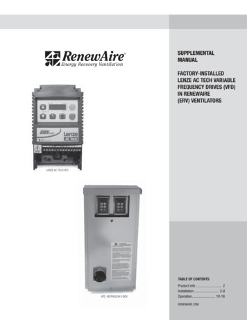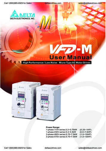
Transcription
P-VFD DUPLEX PUMP SYSTEM MANUAL08-30-20151
Table of Contents1. Safety precautions . 22. Introduction . 33. Installation and wiring . 34. Setup and features. 35. Principle of operation . 46. System start-up . 47. Specifications . 58. Warranty . 51. SAFETY PRECAUTIONSTo prevent injury and property damage, follow these instructions. Failure to adhere toinstallation/operation procedures and all applicable codes may result in hazards as indicatedby warning codes below:The meaning of each symbol in this manual, and on your equipment, is as follows.This is the safety alert symbol. Read and follow instructions carefully to avoid adangerous situation.This symbol alerts the user to the presence of “dangerous voltage” inside the productthat might cause bodily harm or electric shock. This manual should be placed in a location where it can be accessed by users. This manual should be given to the person who actually operating the control panel and isresponsible for its maintenance.2
As with all electrical products, read manual thoroughly. Only qualified, expert personnelshould perform installation and maintenance. Do not disassemble or repair unit unlessdescribed in this manual; death or injury to electrical shock or fire hazard may result.Specifications and manual data are subject to change. Consult factory for additionalinformation.2. INTRODUCTIONThe duplex pump control VFD system can be in configuration of two standalone VFDs, two standardenclosed VFD pump panels or one standard VDP (VFD Duplex Panel) control panel with two VFDs.Enclosed VFD packages are UL-508 listed panels which are designed to meet market requirements andprovide reliable operation. Duplex system has different alternating modes and Lead-Lag control basedon input signals from pressure transducers and VFDs status outputs. The communication between VFDsis based on digital inputs and outputs that makes VFD internal RS-485 communication (Modbus RTU)available for SCADA system, PLCs or other controllers. For two standalone VFDs there are option kits foralternation by VFD selector switch or by momentary pushbutton. For technical specifications and ratingsrefer to VFD manual for standalone VFDs or package specification for enclosed VFDs.There are four duplex control configurations:VFD1#1. Alternation at Every start orat Power up or by TimerVFD2DIC Control wiring#2. Alternation by LeadVFD1 selector switchVFD2DIC Control wiringConfiguration #1 is for two VFDs with only control wiringbetween them. The alternation mode can be set to By Timer, AtPower up or can be configured for alternation At Every Start.Configuration #2 is for two VFDs with control wiring betweenthem and Lead VFD selector switch. The alternation modeshould be set to Lead SW/FLT.ALT SWVFD1VFD1VFD2#3. Alternation at Every start orVFD2at Power up or by TimerDIC Control wiringMomentary PushbuttonALT PBConfiguration #3 is for two VFDs with control wiring betweenthem and one alternating momentary pushbutton. Thealternation mode can be set to By Timer, At Power up or can beconfigured for alternation At Every start. The pushbutton actsas a manual alternator additional to selected alternation mode.3
#4. Alternation at Every startVFD1 or at Power up or by TimerDIC Control wiringHOA1HOA2H O AH O AVFD2Configuration #4 is for two enclosed VFDs with HOA switchesand control wiring between them or VDP panel. The alternationmode can be set to By Timer, At Power up or can be configuredfor alternation At Every start.If other type of alternation is required, please contact FCS techsupport for assistance.The duplex control system requires two pressure transducers (one for each VFD) for redundancy andreliable operation.3. INSTALLATION AND WIRINGCheck if supply voltage matches the voltage rating on the provided drawing & VFD ormanufacturer’s control panel label before wiring and powering up the pump control panel!The duplex VFD control system should be installed in environment suitable for standalone VFDs or theenclosure UL type rating for enclosed VFDs. Refer to P-VFD manual for spacing for proper ventilation.Provide properly sized main disconnect and branch circuit protections where required. The gauge of theinput power, motor and control wiring shell be selected based on the NEC and local law requirements.The power wiring and grounding shell be done by a licensed electrician at the points shown as dashedlines on the provided electrical diagrams. Do not combine input power and motor leads or motor leadsfrom both VFDs in the same conduit.Provide dedicated input power and motor ground wires to VFDs. Using metal construction or conduits asa grounding path could cause improper VFD ground fault protection operation.For the VFD protection and better power filtering it is recommended to install line reactors for each VFDif distance to the service transformer is greater than 50’.For the motor winding protection for 480VAC and 575VAC systems it is recommended to install outputreactor for 45’ to 100’ distance from VFD to a motor, dV/dt output filter from 100’ to 1000’ (800’ forsubmersible pumps) and Sine-Wave filter for greater distances.Power wiring. Wire input power, motor leads and ground wires based on the following drawings:Standalone VFD wiringEnclose VFD wiring4
Control wiring. For DIC (Duplex Interconnection Cable) wiring between two VFDs or two enclosed VFDpanels refer to the following diagrams (VDP panel prewired from the factory). The configurations shownon figures 2, 3 and 4 require extra wiring for optional alternating switch or alternating pushbutton orauxiliary N.C. contact for HOA switch Auto position. Use multi-wire shielded cable for control wiringwith shield drain wire isolated on VFD-1 side and connected on VFD-2 to a ground. Put shrink tube orelectrical tape to isolate bare shield drain wire to protect from shorting any VFD or panel terminals.Use shielded cable for pressure transducer wiring with shield drain wire connected to a ground point atVFD or enclosed VFD panel. Isolate bare shield drain wire with shrink tube or electrical tape and connectit to ground terminal.5
4. SETUP AND FEATURESThe standalone VFDs or VFDs in two enclosed VFD panels should be set to centrifugal or submersiblepump application with all the necessary control and protection features based on provided QSG (quickstart guide). Both VFDs’ parameters should be set identically except VFD ID and Lead/Lag setting. It isrecommended to set all the necessary parameters for VFD-1 then save changes to a keypad and use itskeypad to program VFD-2. Set motor data parameters according to motor nameplate for proper systemoperation and motor protection. Then set all the necessary parameters for basic duplex control andadditional parameters for configurations shown on figures 2, 3 and 4.Basic Duplex Control Parameters6
-35I/O-36I/O-76I/O-77Value/SelectionYES (MMC)40.00Hz30.00HzAnother LeadLag EnableVFD1 or VFD2Timer/Flt or PowerUp/FLTLead VFD or Lag VFD168hrs (7-Days)MMCThis LeadLead Switch Option Parameters (Fig.2)Par. # Value/SelectionI/O-23 LEAD SwitchI/O-34 Lead SW/FLTDescriptionMulti-motor control (Lead-Lag)Lag Stop Frequency. Set 1Hz above [SET-32] sleep frequencyPump speed jump at Lag stop.M3 input set to monitor if another VFD is Lead.When M6 input is activated by Lead VFD, the Lag VFD starts.Identification VFD-1 or VFD-2 for Duplex controlAlternating by Lead run time or at every power-upSet VFD1 to Lead VFD and VFD2 to Lag VFD at initial start-upAlternating time setting in hours (Lead run time).AUX-1 relay output set for MMC (Lag Start) outputLead VFD AUX-2 relay output is active.DescriptionInput for two-position Lead selector switchAlternating Mode set to Lead Selector SwitchAlternating Momentary Pushbutton Option Parameters (Fig.3)Par. # Value/SelectionDescriptionI/O-23 ALT InputInput for momentary N.O. alternating pushbuttonI/O-34 Timer/Flt or PowerUp/FLTAlternating by Lead run time or at every power-upHand-Off-Auto Switch Option Parameters (Fig.4)Par. # Value/SelectionDescriptionI/O-23 HOA Hand/OFF (Not in Auto) M4 Input for N.C. HOA switch contact in Auto positionI/O-34 Timer/Flt or PowerUp/FLTAlternating by Lead run time or at every power-upThe standard VDP packages will come from the factory pre-programmed for duplex control and will onlyrequire programming for motor data parameters and setting of some specific protection and controlfeatures for the application.VDP Duplex Control ParametersPar.#Value/SelectionSET-50 YES (MMC)SET-56 40.00HzSET-63 30.00HzI/O-22 Another LeadI/O-23 HOA Hand/OFF (Not in Auto)I/O-25 Lag EnableI/O-33 VFD1 or VFD2I/O-34 Timer/FltI/O-35 Lead VFD or Lag VFDI/O-36 168 hrsI/O-76 MMCI/O-77 This LeadDescriptionMulti-motor control (Lead-Lag)Lag Stop Frequency. Set 1Hz above [SET-32] sleep frequencyPump speed jump at Lag stopM3 input set to monitor if another VFD is LeadM4 Input for N.C. HOA switch contact in Auto positionWhen M6 input is activated by Lead VFD, the Lag VFD startsIdentification VFD-1 or VFD-2 required for Duplex controlAlternating by Lead run timeSet VFD1 to Lead and VFD2 to Lag at initial start-upAlternating time set to 7 days (Lead run time)AUX-1 relay output set for MMC (Lag Start) outputLead VFD AUX-2 relay output is active.7
5. PRINCIPLE OF OPERATIONBasic duplex control. When power and start signals are applied to both VFDs, the Lead VFD will startand it will activate “This Lead” AUX-2 relay output. Another VFD will receive that signal on “AnotherLead” M3 input and it will switch control to Lag mode. The Lag VFD will start when it receives “LagEnable” signal on M6 input from Lead VFD AUX-1 MMC relay.The Lag VFD will try to maintain pressure in the system by varying pump speed. If demand exceeds theLead pump capacity and system pressure is still below a set-point, Lead VFD will provide AUX-1 “MMC”relay output to start Lag VFD. Both VFDs will maintain pressure until demand decreases below onepump capacity. In this case both VFDs will run at minimum speed and Lead VFD will stop Lag VFD bydeactivating AUX-1 relay. If there is no demand, Lead VFD will switch to sleep mode.If Lead VFD trips on fault or loses power, the Lag VFD will lose signal on M3 input and after short timedelay it will switch control to Lead mode and it will start.The VFD will keep Lead or Lag control mode when it is not powered. If at any point both VFDs becomeLead or Lag, the VFD set in I/O-33 to VFD-1 will take a priority and it will become Lead VFD and VFD-2will become Lag VFD.Alternation Mode Selections. Alternation function for basic duplex control can be set in parameter I/O34 to “Timer/FLT” or “PowerUp/FLT”.When it is set to “Timer/FLT”, VFDs will alternate when Lead VFD run time exceeds the alternating timervalue set in parameter I/O-36. If Lead VFD mode is changed to Lag, its alternating timer will be reset. Inorder to make alternation function test easier, set parameter MAK-55 to I/O-36 value minus one minuteand VFDs will alternate in next two minute.When it set to “PowerUp/FLT”, VFDs will run in the same Lead-Lag sequence until the system powercycle, which will activate an alternation. If only Lag VFD power is cycled, duplex system will notalternate. If Lead VFD power is cycled, duplex system will alternate on Lead VFD fault.Lead switch control option. Lead switch option will not work with VFD packages with installed HOAswitches. Two position Lead switch provides signal to M4 input on VFD-1 or VFD-2 corresponding toswitch current position. The VFD that receives signal on M4 input switches to Lead control mode andanother VFD to Lag mode. If Lead switch position is changed from VFD-1 to VFD-2, VFD-1 becomes LagVFD and stops and VFD-2 becomes Lead VFD and starts. If Lead VFD-2 trips on fault or loses power, LagVFD-1 will become Lead VFD and it will start. When VFD-2 is powered again or fault is reset, VFD2 willbecome Lead again and it will start after VFD-1 is stopped.Alternation pushbutton control option. Alternation pushbutton can be combined with alternating byTimer or at Power-up modes. This option will not work with VFD packages with installed HOA switches.Momentary pushbutton provides pulse signal to M4 input on both VFDs simultaneously to activatealternation. The alternating timer of Lead VFD will be reset during alternation. The Lag VFD thatreceives signal on M4 input switches to Lead control mode and starts its alternating timer. If VFD-1 isLead and it trips on fault, VFD-2 will become Lead and it will start. When VFD-1 fault is rest, it willbecome Lag VFD.HOA switch control option. HOA switch option will not work with Lead switch and AlternationPushbutton options. N.C. contact on Auto position of each HOA provides signal to “HOA Hand/Off” M4input on each VFD when HOA is in Auto position. If Lead VFD HOA position is changed from Auto to Offor Hand, VFD will become Lag and another VFD with HOA in Auto position will be Lead. If both HOAs arein Off position and then VFD-2 HOA is switched to Auto, VFD-2 will become Lead.8
The VFD that receives signal on M4 input switches to Lead control mode and another VFD to Lag mode.If Lead switch position is changed from VFD-1 to VFD-2, VFD1 becomes Lag VFD and stops and VFD-2becomes Lead VFD and starts. If Lead VFD-2 trips on fault or loses power, Lag VFD-1 will become LeadVFD and it will start. When VFD-2 is powered again or fault is reset, VFD-2 will become Lead again and itwill start after VFD1 is stopped.Alternation at every start. Alternation at start can be combined with Basic Duplex configuration or HOAswitch control option. This mode requires common start signal for bothVFDs and extra wiring shown on figure #5. When start contact is closed,both VFDs will close their AUX-3 relay outputs for two seconds andalternation mode will be activated during Run Time Delay. Then newlyassigned Lead VFD will start.If run command is present during power-up, VFDs will alternate. If VFD-1is Lead and it trips on fault, VFD-2 will become Lead and it will start. WhenVFD-1 fault is rest, it will become Lag VFD.See below a parameter list for alternation at start setup.Duplex Control with Alternation at Start ParametersPar.#Value/SelectionDescriptionI/O-21 ALT InputAlternation input for momentary pushbuttonI/O-45 M7 (Default)In-Out Timer Input SelectionI/O-46 ONE PulseTimer mode selectionI/O-47 2 sec.Timer time settingI/O-48 Normal Open (Default)In-Out timer input selection N.O. or N.C.I/O-78 In-Out TimerAUX-3 relay output6. SYSTEM START-UPPower-up both VFDs and check the rotation of each pump in Hand or Local mode. If rotation is incorrect,swap any two motor wires coming for the pump. Return control to Remote or Auto mode.Adjust desired system pressure set-point (PSI) in each VFD parameter DRV-00 or SET-26. Run system atmaximum demand. Lead VFD should increase frequency to maximum and then Lag VFD should start.Both VFDs should maintain system pressure set-point. Then close demand and VFDs should decreasefrequency to minimum and Lag pump will stop. After Sleep mode time delay VFD will increase pumpspeed to reach a boost pressure set-point. When system pressure is greater than boost pressure orboost timer is expired, Lead VFD will go to sleep mode. Open lowest demand line and when pressuredrops below wake-up level, Lead VFD will start and it should maintain pressure set-point (Lag VFD instop mode). Close line (no demand) and wait until VFD decreases speed and after pressure boost goes tosleep mode. Open maximum demand and when Lead VFD starts turn its power off. Lag VFD should startas Lead VFD and run at full speed. Turn the power on to another VFD and after approximately 15seconds it should start and both VFDs will maintain a pressure set-point. Close demand, both VFDsshould decrease frequency to minimum, Lag VFD will stop and then Lead VFD will go to sleep mode.9
This manual is applicable to all FCS (Cerus) VFDs and Enclosed VFD panels shipped after July 1st, 2015.Disconnect and lock out all power before installing or servicing equipment.This equipment may require locking out multiple power sources prior to service.Warranty InformationFCS provides 5-year warranty for all FCS brand electrical components excluding thermalprotection devices. All other brand name devices installed in FCS control panels will carryoriginal manufacturer warranties.Warranty period is 60 months after date of invoice. Detailed warranty terms and conditionsare available from FCS or can be found at www.cerusind.com Warranty service informationoIf standalone VFDs or enclosed VFD packages do not operate properly because of any defectivecomponent under normal and proper use within the warranty term, contact an authorized FCSdistributor or FCS technical support. Warranty is void if damage to the unit was caused by any of the following:oooooMisuse, negligence or accident.Abnormal supplied power voltage.Improper repair or altering by other than a FCS authorized distributor or service center.Earthquake, fire, flooding, lighting, or other natural calamitiesWhen the warranty period has expired10
The duplex VFD control system should be installed in environment suitable for standalone VFDs or the enclosure UL type rating for enclosed VFDs. Refer to P-VFD manual for spacing for proper ventilation. Provide properly sized main disconnect and branch circuit protections where required. The gauge of the