Transcription
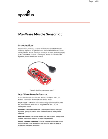
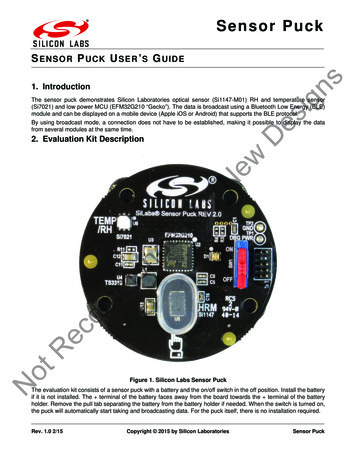
Sensor PuckesignsS ENSOR P U C K U SER ’ S G UIDE1. IntroductionThe sensor puck demonstrates Silicon Laboratories optical sensor (Si1147-M01) RH and temperature sensor(Si7021) and low power MCU (EFM32G210 “Gecko”). The data is broadcast using a Bluetooth Low Energy (BLE)module and can be displayed on a mobile device (Apple iOS or Android) that supports the BLE protocol.DBy using broadcast mode, a connection does not have to be established, making it possible to display the datafrom several modules at the same time.NotRecommendedforNew2. Evaluation Kit DescriptionFigure 1. Silicon Labs Sensor PuckThe evaluation kit consists of a sensor puck with a battery and the on/off switch in the off position. Install the batteryif it is not installed. The terminal of the battery faces away from the board towards the terminal of the batteryholder. Remove the pull tab separating the battery from the battery holder if needed. When the switch is turned on,the puck will automatically start taking and broadcasting data. For the puck itself, there is no installation required.Rev. 1.0 2/15Copyright 2015 by Silicon LaboratoriesSensor Puck
S en so r P u c kThe data that is broadcast is generally displayed on a mobile device. To display the data the Silicon Labs SensorPuck app must be installed on the mobile device. The application is available for no charge from the Apple AppStore or the Google Play Store. (Search for Silicon Labs Sensor Puck.) esigns3. OperationEnvironmental mode Measuresambient light, UV index, ambient temperature, and ambient humidity.is the default mode of operation and the lowest power. In this mode of operation measurements are taken and broadcast (once per second). The LED flashes green once per measurement cycle. The battery current consumption in this mode is approximately 1.5 mA average, which means that a standard CR2032battery will last about five days. The battery for this demo is not rechargeable so it must be replaced if it is depleted. ThisBiometric modeD the once per second interval for environmental monitoring, the puck checks for the presence of an object over theSi1147-M01 (under the acrylic cover). If an object is detected the puck will go into biometric mode and attempt to measure heart rate. Heart rate is measured by the reflection of IR light from an LED inside the Si1147-M01. The light is reflected from a finger-tip to measure the heart rate. In biometric mode the power consumption goes up to 7 mA, so battery life will decrease to about one day in this mode. In biometric mode, the LED will flash red while it is acquiring the heartbeat and then switches to continuous green oncethe heartbeat has been acquired. To avoid excessive power drain in case the puck is left on and covered with an object, the puck will exit biometric modeafter 90 seconds. In this case, the object must be removed and a finger should be placed over the acrylic cover to startbiometric monitoring again. The data from the puck is broadcast over a BLE “advertisement” packet. The mobile device that displays the data doesnot need to make a connection to the puck. For this reason, it possible that a single mobile device (i.e. a phone) candisplay data from multiple pucks.NotRecommendedforNew At2Rev. 1.0
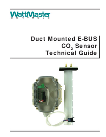
S en so r P u ck4. Sensor Puck ApplicationsThere is a Sensor Puck app for iOS devices and another Sensor Puck app for Android devices. Both apps arenamed “Silicon Labs Sensor Puck”.esignsThe iOS Sensor Puck app can be installed from the Apple App Store. The iOS app runs on devices with iOS 7 andhigher, and has Bluetooth 4.0 hardware. Silicon Labs has verified that the iOS app runs on iPhone 4S, 5, 5S, 6 and6 Plus. The iOS app also runs on iPad 3 and 4.The Android Sensor Puck app can be installed from the Google Play Store. The Android app runs on devices withAndroid version 4.3 and higher, and has Bluetooth 4.0 hardware. Silicon Labs has verified that the Android appruns on the following devices: Samsung Galaxy S4, Samsung Galasy S5, Samsung Galaxy Tab 3, MotorolaMoto E, Motorola Moto G, HTC Desire, HTC One Max, LG Nexus 5, LG G Flex, Sony Z1, Sony T2 Ultra, and AsusNexus 7.NotRecommendedforNewDWhen the puck is in environmental mode, the Silicon Labs Sensor Puck app displays the environmental screen:Figure 2. Android Environmental ScreenRev. 1.03
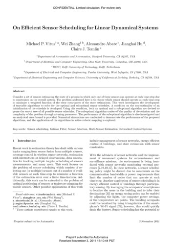
S en so r P u c kThe environmental screen displays the environmental sensor measurements and the battery status. The puckname is displayed at the top of the screen. The temperature scale can be changed between Celsius andFahrenheit by tapping the small C and F buttons.Figure 3. Android Biometric ScreenNotRecommendedforNewDesignsWhen the puck is in biometric mode, the Android Sensor Puck displays the biometric screen.4Rev. 1.0
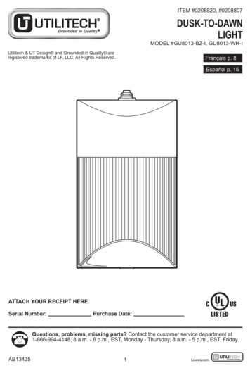
S en so r P u ckmendedforNewDesignsThe iOS Sensor Puck app does not have a biometric screen. The iOS app displays the heart rate in the lower rightcorner of the environmental screen:NotRecomFigure 4. iOS Environmental ScreenRev. 1.05
S en so r P u c kmendedforNewDesignsIf there are several sensor pucks, you can use the navigation drawer to select a different puck. To open thenavigation drawer, tap on the three-line icon in the upper left corner of the screen or swipe from the left edge of thescreen.NotRecomFigure 5. Navigation Drawer6Rev. 1.0
S en so r P u ckmendedforNewDesignsYou can change the name of a puck by tapping on the edit icon to the right of the puck name.NotRecomFigure 6. Puck NameRev. 1.07
S en so r P u c k5. Sensor Puck Hardware Description5.1. SchematicsesignsFigure 7 shows the block diagram of the puck with debug header MCU, the sensors, and the Bluetooth 04-RHTMCUHEADER 2x5/SMREDGREENNewDebug pinsSWO PF2SWDIO PF1SWCLK PF0RESETDLEDsINT246810I2C0 SCL13579I2C0 SDA13579TP2GNDBLE RESETLEU0 TXLEU0 RXBLE WAKEHOST WAKE02-MCUREDGREEN07-LEDsBLEBLE RESETBLE TXBLE RXBLE WAKEHOST WAKEfor05-BLEFigure 7. Block DiagrammendedFigure 8 shows the power section. The CR2032 battery is used to power most of the ICs. A boost converter is usedto produce 4.1 V which is used to power the LED of the Si1147 so it can be driven at higher current than is possiblewith a coin cell battery.DebugSW1SW SLIDE 2POS312VMCUomR1147high 4.1V low 5.0VL1 5V47uHBH10.1uF2453120mm BATTERY HOLDERINS0S1S2LSWOUTSTOREVGOODOUT ONU4 NEGC11Figure 8. Power SectionFigure 9 shows the EFM32G210 “Gecko” MCU. The 24 MHz clock is only used in active periods. For lower powerconsumption, the internal 32 KHz R-C clock is used as much as possible. A special calibration routine is used tocalibrate the 32 KHz clock against the 24 MHz crystal for accuracy in the UART communication speed while in lowpower mode.8Rev. 1.0
S en so r P u ckVMCUVMCUesignsC6 0.1uFC4 0.1uFC3 0.1uFC2 0.1uFC5 0.1uFConnect together thenconnect tp power planeConnect together thenconnect tp power planeC710uFC81.0uFHOST F3XTAL2DR10 4.99KR9 4.99KDBG SWODBG SWDIODBG SWCLKRXTXSWO PF2SWDIO PF1SWCLK PF0INTI2C0 SCLI2C0 SDALEU0 RXLEU0 TXmendedfor24MHzR8 4.99K21DEC2041428VDD 5PD40RESETPA0PA1PA2PC0PC1PB7PB8VSS/EPAD1235678BLE RESETBLE WAKEREDGREENAVDDAVDD1511VMCUU2EFM32G210Figure 9. EFM32G210 MCUFigure 10 shows the Si7021 RH and temperature sensor as well as the Si1147-M01 optical 5VMCU78C170.1uF92om 5V10 2SWLFDO SensorNotC160.1uFFigure 10. SensorsFigure 11 shows the BLE module and LEDs.Rev. 1.09
S en so r P u c k3BCM20732iBLUETOOTH 5BLE RESETBLE TXBLE RXBLE WAKEHOST WAKETPV6Prgm UART RXPRGM UART TXSCLSDAEEPROMWPRSTbHOST UART TXHOST UART RXWAKE MODULEWAKE VMCUNewFigure 11. BLE Module and LEDs5.2. Bill of MaterialsTable 1. Sensor Puck BOMReference1 C120 mm BATTERYHOLDERTolManufacturerPart NumberBAT-HLD-001ManufacturerLINX TECHNOLOGIES INC.0.1 µF16 V 10%C0402X7R160104KVenkel8 C2,C3,C4,C5,C6,C11 0.1 µF, C16,C1710 V 10%C0402X7R100104KVenkel1 C710 µF6.3 V 20%C0603X5R6R3- Venkel106M1.0 µF6.3 V 10%C0402X5R6R3- Venkel105K10 pF50 V 5%C0402C0G500- Venkel100J47 µF6.3 V 20%C0805X5R6R3- Venkel476Mom1 C8ec2 C9,C10R2 C12,C131 D1598-8410-207CF1 J1Header 2x5 THNot10Voltagemended1 BH1ValueforQuantity598-8410-207CF DialightM50-3500542Harwin1 L147 µH 20%3 R3,R4,R510 K 1%CR0402-16W1002FVenkel3 R8,R9,R104.99 K 1%CR0402-16W4991FVenkelRev. 1.0NR 3012T 470M Taiyo Yuden
S en so r P u ckTable 1. Sensor Puck BOM turerPart NumberManufacturer47 1%CR0402-16W47R0FVenkel2 R13,R142K 1%CR0402-16W2001FVenkel4 SF4,SF5,SF6,SF7BUMPERSJ61A61 SW1SW SLIDE 2POSNK236HRED1 U1BCM20732i3.3 V1 U2EFM32G2103.3 V1 U324 MHz1 U4TS33105Vmended5.3. LayoutApem 0F12 SiLabs8-QFN32for2 TP1,TP21 U63MDN/ANew4 TPV1,TPV2,TPV5,TP TPVV61 U5esigns1 R11FA-23824.0000MBEpsonTS3310ITD1022 SiLabsOptical SensorSi1147-M01-GM SiLabsSi7021Si7021-A10-GM1 SiLabsNotRecomFigure 12 shows the layout of the puck. The Bluetooth module has a keep and area and is placed on the backsideto avoid antenna detuning. The inner power and ground layers are not shown.Figure 12. Silkscreen, Front and Back MetalRev. 1.011
S en so r P u c k6. Sensor Puck FirmwareNo firmware download is necessary to use the puck as it comes preprogrammed with firmware, but the capability toview and modify the firmware source code is available in Simplicity Studio.esignsIt is possible to download, debug, and even modify this code within Simplicity Studio, however, to connect the puckto Studio you will need two additional pieces of hardware. First, a standard 9-pin Arm Cortex debug cable isrequired (not supplied). This cable can be ordered from Segger (see the link xm.htmlSecondly, an EFM32 development kit with a 20-pin debug out header, such as the Zero Gecko STK, is required(also not supplied). The cable connects the 20-pin debug out header on the EFM32 development kit to the 9-pindebug header on the puck (J1). NotRecommendedfor Install and launch the latest version of Simplicity Studio (www.silabs.com/simplicity).Connect the 20-pin header of the programming/debug cable to the EFM32 development kit.Connect the 9-pin header of the programming debug cable to the Sensor Puck.Slide Sensor Puck power switch to ‘ON’.Select DBG mode on the power switch of the EFM32 development kit.Connect a USB cable from PC to EFM32 Development kit J-Link connector.If the EFM32 development kit is not connected automatically, select ‘Detect Connected Device’.Once the kit is recognized, select the tile ‘Kit Manager’ shown below to configure the development kit to debugout mode.New DSteps to program the firmware of the Sensor Puck:Figure 13. Simplicity Studio Launch Screen12Rev. 1.0
S en so r P u ckecommendedforNewDesignsNext, set the debug mode to ‘Out’ in the dialog shown below.Figure 14. Kit Manager DialogRTo use the development kit subsequently without the puck, it is necessary to revert this setting beforedisconnecting the puck.NotTo open the source code in Simplicity Studio, launch the Software Examples wizard by clicking on the SoftwareExamples tile (see Figure 13). Then select Sensor Puck as the kit. Click ‘Next’ and select the sensor puck sourcecode.This will load the source code in the Silicon Labs IDE where it can then be viewed, edited, compiled, anddownloaded from within Simplicity Studio. The details of doing this are beyond the scope of this document.Note: Sensor Puck is planned to be supported in V3.0 of Simplicity Studio. Prior to V3.0, the source code will be provided atwww.silabs.com/sensor-puck. To load the project into Simplicity Studio, use the steps in the readme document in this linkinstead of the Software Examples wizard.Rev. 1.013
y-Friendly.www.silabs.com/productsQualitySupport and mNotRecDisclaimerSilicon Laboratories intends to provide customers with the latest, accurate, and in-depth documentation of all peripherals and modules available for system and software implementers usingor intending to use the Silicon Laboratories products. Characterization data, available modules and peripherals, memory sizes and memory addresses refer to each specific device, and"Typical" parameters provided can and do vary in different applications. Application examples described herein are for illustrative purposes only. Silicon Laboratories reserves the right tomake changes without further notice and limitation to product information, specifications, and descriptions herein, and does not give warranties as to the accuracy or completeness of theincluded information. Silicon Laboratories shall have no liability for the consequences of use of the information supplied herein. This document does not imply or express copyright licensesgranted hereunder to design or fabricate any integrated circuits. The products are not designed or authorized to be used within any Life Support System without the specific written consentof Silicon Laboratories. A "Life Support System" is any product or system intended to support or sustain life and/or health, which, if it fails, can be reasonably expected to result in significantpersonal injury or death. Silicon Laboratories products are not designed or authorized for military applications. Silicon Laboratories products shall under no circumstances be used inweapons of mass destruction including (but not limited to) nuclear, biological or chemical weapons, or missiles capable of delivering such weapons.Trademark InformationSilicon Laboratories Inc. , Silicon Laboratories , Silicon Labs , SiLabs and the Silicon Labs logo , Bluegiga , Bluegiga Logo , Clockbuilder , CMEMS , DSPLL , EFM , EFM32 ,EFR, Ember , Energy Micro, Energy Micro logo and combinations thereof, "the world’s most energy friendly microcontrollers", Ember , EZLink , EZRadio , EZRadioPRO , Gecko ,ISOmodem , Precision32 , ProSLIC , Simplicity Studio , SiPHY , Telegesis, the Telegesis Logo , USBXpress and others are trademarks or registered trademarks of Silicon Laboratories Inc. ARM, CORTEX, Cortex-M3 and THUMB are trademarks or registered trademarks of ARM Holdings. Keil is a registered trademark of ARM Limited. All other products or brandnames mentioned herein are trademarks of their respective holders.Silicon Laboratories Inc.400 West Cesar ChavezAustin, TX 78701USAhttp://www.silabs.com
Mouser ElectronicsAuthorized DistributorClick to View Pricing, Inventory, Delivery & Lifecycle Information:Silicon Laboratories:SENSOR-PUCK
The iOS Sensor Puck app can be installed from the Apple App Store. The iOS app runs on devices with iOS 7 and higher, and has Bluetooth 4.0 hardware. Silicon Labs has verified that the iO S app runs on iPhone 4S, 5, 5S, 6 and 6 Plus. The iOS app also runs on iPad 3 and 4. The Android Sensor Puck app can be installed from the Google Play Store.