Transcription
Duct Mounted E-BUSCO2 SensorTechnical Guide
TABLE OF CONTENTSSENSOR OVERVIEW . 3Features . 3Environmental Requirements . 3DUCT MOUNTED CO2 SENSOR INSTALLATION . 4DUCT MOUNTED E-BUS CO2 SENSOR MOUNTING & WIRING TO DDC CONTROLLER . 6TROUBLESHOOTING . 7Using LEDs to Troubleshoot . 7Altitude Correction . 7TB1 Terminal Block (CO2 Reading) . 7PART NUMBER CROSS REFERENCE TABLEPART DESCRIPTIONPART NO.Duct Mounted E-BUS CO2 Sensor with Remote Pickup TubeOE256-07-GWall Mounted E-BUS CO2 SensorOE256-05-GE-BUS LCD Digital Room Sensor Temp OnlyOE217-02-GE-BUS LCD Digital Room Sensor Temp & RHOE217-03-GE-BUS Digital Room Sensor Temp & RHOE217-04-GEBC E-BUS Cables - varying lengthsEBC-XXXF-GDDC ControllerOE377-26B-00001WattMaster Controls Inc.8500 NW River Park Drive · Parkville, MO 64152Toll Free Phone: 866-918-1100 PH: (816) 505-1100DAIKIN is a registered trademark of Daikin Industries, LTDWattMaster Form: DK-DM-EBUS-CO2-TGD, Revision 01ACopyright June 2016 WattMaster Controls, Inc.Neither WattMaster Controls, Inc. nor Daikin Industries, Ltd.assumes any responsibility for errors or omissions in thisdocument and are separate companies.This document is subject to change without notice.
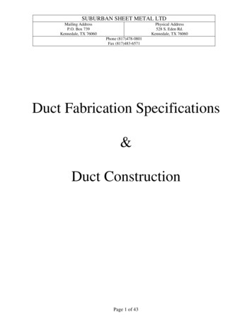
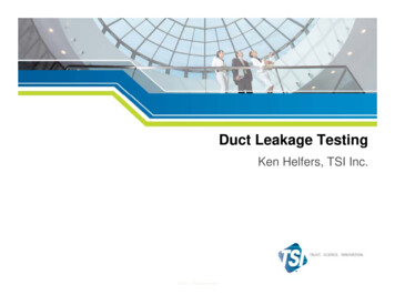
DUCT MOUNTED E-BUS CO2 SENSORSensor OverviewOverviewEnvironmental RequirementsThe OE256-07-G Duct Mounted E-BUS CO2 Sensor with RemotePickup Tube is used for monitoring duct CO2 levels and is designedfor permanent mounting in the Return Air duct. It utilizes an aspiration box to accurately capture CO2 levels in the duct. It connects to theDDC Controller by using an E-BUS cable with E-BUS connectors. SeeFigure 1 for dimensions.The Duct Mounted E-BUS CO2 Sensor needs to be installed in anenvironment that can maintain a temperature range between 14 F and122 F and a humidity range between 5% and 95% RH NGSFOR0.170 I.D.TUBING4.06"HINGEDCOVER5.00"The Wall Mounted E-BUS CO2 Sensor (OE256-05-G) is used for monitoring space CO2 levels and is designed for permanent wall mounting inthe conditioned space. It connects to the DDC Controller using an EBCE-BUS Expansion Cable. It can be daisy-chained with the E-BUS DigitalRoom Sensor (OE217-02-G, OE217-03-G, OE217-04-G) for applications requiring both a space CO2 sensor and space temperature sensor.For more information, refer to the Daikin OE256-05 Wall Mounted CO2Sensor Technical Guide.Some typical applications are: SENSORHOUSINGControlling ventilation to ensure excess outdoor air is notcausing energy wasteEnsuring good air distribution throughout building zones13 2" Controlling ventilation in a building where the occupancyvaries frequentlyE-BUS CONNECTORFEMALE END3M4 3 2 1 FeaturesCO2 SENSOR, HOUSING AND CABLE ASSEMBLYBRASSBARBFITTINGSFOR0.170 I.D.TUBINGThe CO2 Sensor provides the following: A very accurate and stable sensor guaranteed to maintainits accuracy due to infrared self-calibration feature of sensor0.6”Sensor accuracy of /- 50 ppm @ 1000 ppm or 2% of themeasured valueAnnual drift of /- 2 ppm per year8.3"CO2 PICKUP TUBE (PROVIDED WITH SENSOR)EBC-10F"WATTMASTER EBUS""WATTMASTER EBUS"EBC-10F4 3 2 13M Uses the patented dual beam Non-Dispersive Infrared (NDIR) technology3M4 3 2 1 Measurement range of 0 to 2000 ppmHB LED under front cover shows active CO2 sensing120 9”E-BUS CONNECTOR EXTENSION CABLE WITH MALE ENDS (PROVIDED WITH SENSOR)120 9”0.170 I.D. FIRE RATED TUBING (PROVIDED WITH SENSOR)Figure 1: Duct Mounted E-BUS CO2 Sensor withRemote Pickup Tube DimensionsTechnical Guide3
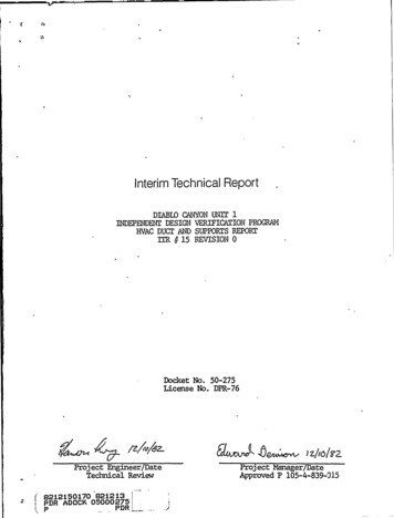
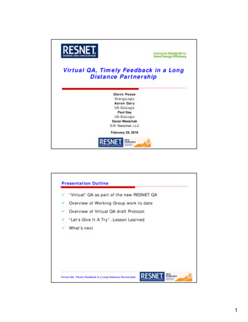
DUCT MOUNTED E-BUS CO2 SENSORSensor InstallationInstallationTo install the Duct Mounted E-BUS CO2 Sensor, please follow theinstructions below. See Figure 2, page 5 for detailed illustrations of theDuct Mounted E-BUS CO2 Sensor and its components.STEP 1: Find the general location on the side of the Return AirDuct where you want to mount the CO2 Sensor. Be sure to locatethe box with the airflow in the proper direction per the airflowlabel. A conduit clamp is provided to help seal the opening wherethe sensor cabling penetrates the aspiration box housing.STEP 4: Mount the remote pickup tube assembly separately tothe ductwork by first cutting a 11/4” diameter hole in the ductworkwall. Then insert the remote pickup tube into the hole. Securethe remote pickup tube to the ductwork by inserting (2) suppliedsheet metal screws through the (2) mounting holes in the remotepickup tube mounting plate and securing the remote pickup tubeassembly by screwing it to the ductwork using a manual orpowered screw driver to tighten the screws.STEP 5: Using the supplied 10 ft. long tubing, connect theremote pickup tube to the aspiration box assembly, cutting thetubing to fit.STEP 2: Connect the sensor’s attached cable which has a JackE-BUS connector to the provided EBC E-BUS Cable. Thenconnect the EBC E-BUS Cable to the DDC Controller or EBCHub or Adapter Board and to the DDC Controller.STEP 3: Secure the sensor in its aspiration box assembly to theductwork with the (2) supplied sheet metal screws.4Technical Guide
DUCT MOUNTED E-BUS CO2 SENSORSensor InstallationSECURE CO2 SENSORASSEMBLY TO DUCT ORUNIT HOUSING WITHSHEET METAL SCREWS(BY OTHERS)RETURN AIRDUCT SIDE WALLCO2 SENSORASSEMBLYROUTE SUPPLIEDFIRE RATED 0.170 I.D.TUBING FROM C02PICKUP TUBE PORTS TOSENSOR HOUSING PORTSCO2 PICKUPTUBE ASSEMBLYCUT 1-1/4” DIAMETERHOLE IN DUCT FOR CO2PICKUP TUBE INSERTIONSECURE CO2 PICKUP TUBEASSEMBLY TO DUCT WITHSUPPLIED SHEET METAL SCREWS3M4 3 2 1M31 2 3 4DDC CONTROLLERSUPPLY AIR TEMPSUPPLIED E-BUSEXTENSION CABLECONNECTED BETWEENCO2 SENSOR E-BUSCONNECTOR AND E-BUSCONNECTOR ON DDC,E-BUS HUB, OR ADAPTERBOARD3M4 3 2 1Figure 2: Mounting and Cable Installation for Duct Mounted E-BUS CO2 SensorTechnical Guide5
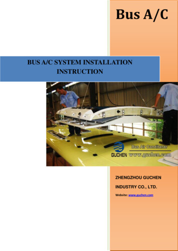
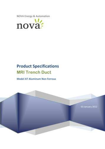
DUCT MOUNTED E-BUS CO2 SENSORDuct Mounted E-BUS CO2 Sensor Wiring to DDC ControllerDuct Mounted E-BUS CO2 SensorThe OE256-07-G Duct Mounted E-BUS CO2 Sensor with Remote PickupTube is used for sensing the current CO2 level in the HVAC unit’s returnair stream. This is useful when you want an average CO2 reading in thearea served by the HVAC unit or when you don’t want a wall mountedE-BUS CO2 Sensor due to sensor tampering concerns in the space.The Duct Mounted Return Air E-BUS CO2 Sensor with Remote PickupTube is designed to be mounted in the return air duct of the HVAC unitand uses its integral aspiration box to sample the CO2 level in the duct.See Figure 3 below for wiring and installation details.NOTE:If using multiple E-BUS Sensors or Modules, theE-BUS Hub or Adapter Board may be required.The OE256-07-G Duct Mounted Return Air CO2 Sensor is comprised ofthe CO2 Sensor, the WattMaster Aspiration Box Assembly, and a RemotePickup Tube. See the dimensional and installation information in Figures2 & 3 for mounting, wiring, and installation details.Note:1.) The Duct Mounted E-BUS CO2 SensorConnects To The DDC Controller Using AnEBC E-BUS Cable Of The Required LengthOr The Provided 10 Foot EBC Cable.OE256-07-G Duct MountedE-BUS CO2 SensorSUPPLY AIR TEMP1.6 PC 37X041.23M4 3 2 1EBC E-BUSCablewith JackConnectionDDC Controller10 Foot EBCE-BUS Cable(Provided)Figure 3: Duct Mounted E-BUS CO2 Sensor & Digital Room Sensor Wiring for DDC Controller6Technical Guide
DUCT MOUNTED E-BUS CO2 SENSORTroubleshootingHB LEDInitially, the HB LED blinks fast for 30 seconds. It will then blink every30 seconds. A CO2 sample is taken once every 30 seconds.Altitude CorrectionT- 12HBLEDCOMMLEDJ1COMM LEDThe COMM LED blinks on whenever communications are sensed.GLEDs are available for troubleshooting the CO2 Sensor. There are twoLEDs that are visible at an angle through the plastic cover. See Figure4 for locations.R Using LEDs to TroubleshootAltitude correction can be configured using PrismD software installedon a computer. The altitude can be configured at a value of 0-15,000feet. The default is 500 feet.TB1 Terminal Block (CO2 Reading)Figure 4: OE256-07-G Board LEDsThe TB1 terminal block should only be used to test the sensor when thesensor cable is plugged into the controller and the sensor and controllerare powered up. Directions: Set the meter for DC volts and connect theGND probe to the GND terminal and the probe to the CO2 0-5 terminal.Look at the output voltage and record it. Multiply the voltage times 400.The value should match the CO2 as read on the System Manager TouchScreen II or PrismD. If the signal doesn’t match the sensor reading, callWattMaster Controls for a replacement.Technical Guide7
Form: DK-DM-EBUS-CO2-TGD, Revision 01A Printed in the USAJune 2016All rights reserved.Copyright 2016WattMaster Controls Inc. 8500 NW River Park Drive Parkville, MO 64152
432 1ebc-10f"wattmaster ebus" "wattmaster ebus" 120 " 9 120 " 9 e-bus connector extension cable with male ends (provided with sensor) 0.170 i.d. tubing (provided with sensor)fire rated co2 pickup tube (provided with sensor) co2 sensor, housing and cable assembly 5.00" 4.12" 2.55" 13 2" 8.3" 0.6" 4.06" 2.81" figure 1: duct .