Transcription
DELTA 400012 kV Insulation Diagnostic SystemReference ManualApplications GuideWWW.MEGGER.COMZM-AH02E
DELTA 400012 kV Insulation Diagnostic SystemReference ManualApplications GuideNOTICE OF COPYRIGHT & PROPRIETARY RIGHTS 2010, Megger Sweden AB. All rights reserved.The contents of this manual are the property of Megger SwedenAB. No part of this work may be reproduced or transmitted inany form or by any means, except as permitted in written licenseagreement with Megger Sweden AB. Megger Sweden AB has madeevery reasonable attempt to ensure the completeness and accuracyof this document. However, the information contained in thismanual is subject to change without notice, and does not representa commitment on the part of Megger Sweden AB. Any attachedhardware schematics and technical descriptions, or software listingsthat disclose source code, are for informational purposes only.Reproduction in whole or in part to create working hardware orsoftware for other than Megger Sweden AB products is strictlyprohibited, except as permitted by written license agreement withMegger Sweden AB.TRADEMARK NOTICESMegger and Programma are trademarks registered in the U.S.and other countries. All other brand and product names mentionedin this document are trademarks or registered trademarks of theirrespective companies.Megger Sweden AB is certified according to ISO 9001 and 14001.SWEDENUNITED STATESMegger Sweden ABEldarvägen 4Box 2970SE-187 29 TÄBYSwedenMegger2621 Van Buren AvenueNorristown, PA 19403T 46 8 510 195 00F 46 8 510 195 95seinfo@megger.comwww.megger.comEDENZM-AH02EUSAT 1 610 676 8500F 1 610 676 8610VFCustomerSupport@megger.comwww.megger.com3
Contents1 Introduction. 6Introduction. 28General. 6Oil circuit-breakers. 28Principle of operation. 6Air-blast circuit-breakers. 30SF6 Circuit-breakers. 31Current, capacitance and dissipation factorrelationship. 7Vacuum circuit breakers. 32Connections for UST/GST Configurations. 8Oil circuit reclosers. 33Air magnetic circuit-breakers. 332 Interpretation of measurements. 10Rotating machines. 33Significance of capacitance anddissipation factor. 10Cables. 35Dissipation factor (Power factor) of typicalapparatus insulation. 11Introduction. 35Permittivity and % DF of typical insulatingmaterials. 11Test procedure. 36Significance of temperature. 12Liquids. 37Significance of humidity. 13Test procedure. 37Surface leakage. 13Miscellaneous assemblies and components. 37Electrostatic interference. 14High-Voltage turns-ratio measurements. 38Negative dissipation factor. 14Connected bus work, cables etc. 143 Testing power system components. 16Transformers. 16Introduction. 16Definitions. 16Surge (lightning) arresters. 35Test connections. 36Test results. 36Test procedure. 38Temperature considerations. 38Index. 40References. 42Appendix ATemperature correction tables. 44Two-winding transformers. 16Three-winding transformers. 18Autotransformers. 19Transformer excitation current tests. 19Shunt reactors. 21Potential transformers. 21Current transformers. 21Voltage regulators. 21Dry-type transformers. 22Bushings. 22Introduction. 22Definitions. 22Bushing troubles. 24Bushing tests. 24Inverted tap to center conductor test C1 (UST). 26Power and dissipation factor & capacitance test C2. 26Hot collar test. 27Spare bushing tests. 27Circuit breakers. 284DELTA 4000ZM-AH02E
ZM-AH02EDELTA 40005
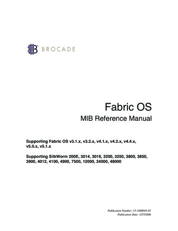
1 Introduction1IntroductionGeneralPrinciple of operationThe intention of this reference-application manual is toguide the operator in the appropriate method of makingcapacitance and dissipation factor/power factor measurements on power apparatus and to assist in the interpretationof test results obtained. It is not a complete step-by-stepprocedure for performing tests.Most physical test objects can be accurately represented asa two or three-terminal network. An example of a twoterminal capacitor is an apparatus bushing without any testtap. The center conductor is one terminal and the mounting flange (ground) is the second terminal. An example ofa three-terminal capacitor is an apparatus bushing whichhas a power factor or capacitance tap. The center conductor is one terminal, the tap is the second terminal, and themounting flange (ground) is the third terminal.Before performing any test with this apparatus, read theuser manual and observe all safety precautions indicated.It is possible to have a complex insulation system thathas four or more terminals. A direct measurement of anycapacitance component in a complex system can be madewith this test set since it has the capability for measuringboth ungrounded and grounded specimens.Figure 1 shows a simplified measuring circuit diagram ofthe DELTA 4000 test set measuring a two-winding transformerin UST test mode. The test voltage is connected to the HVterminal and the current is measured at the LV terminal.Voltage and current are accurately measured in amplitudeand phase and CHL capacitance, dissipation factor, powerloss etc are calculated and displayed.Figure 1: UST-R test setup for a 2-w transformerDissipation factor measurements can generally be performed with two different configurations, UST (Ungrounded Specimen Test) where the ground act as natural guardor GST (Grounded Specimen Test) with or without guard.Figure 2 shows a guarded UST measurement. The currentflowing through CHL is measured but the current pathsthrough CH and CL is guarded/grounded and not measured. Figure 3 shows a guarded GST measurement wherethe CH current to ground is measured but the currentthrough CHL is guarded and measured.6DELTA 4000ZM-AH02E
1 IntroductionCurrent, capacitance anddissipation factor relationshipIn an ideal insulation system connected to an alternatingvoltage source, the capacitance current Ic and the voltageare in perfect quadrature with the current leading. In addition to the capacitance current, there appears in practicea loss current Ir in phase with the voltage as shown inFigure 5.Figure 2: UST connection for measuring CHL in a two-winding transformerThe current taken by an ideal insulation (no losses, Ir 0)is a pure capacitive current leading the voltage by 90 (q 90 ). In practice, no insulation is perfect but has a certainamount of loss and the total current I leads the voltage bya phase angle q (q 90 ). It is more convenient to use thedielectric-loss angle d, where d (90 - q). For low powerfactor insulation Ic and I are substantially of the same magnitude since the loss component Ir is very small.The power factor is defined as:Power factor cos Θ sin δ IrIand the dissipation factor is defined as:Figure 3: GST connection for measuring CH in a two-winding transformerDissipation factor cot Θ tan δ PF DF 1 DF2DF PF 1 – PF2IrIcThe DELTA 4000 is able to display either dissipation factoror power factor based on user’s choice.Figure 5: Vector diagram insulation systemIn cases where angle d is very small, sin d practically equalstan d. For example, at power factor values less than 10percent the difference will be less than 0.5 percent of reading while for power factor values less than 20 percent thedifference will be less than 2 percent of reading.The value of Ic will be within 99.5 percent of the value Ifor power factor (sin d) values up to 10 percent and within98 percent for power factor values up to 20 percent.ZM-AH02EDELTA 40007
1 IntroductionConnections for UST/GSTConfigurationsDELTA 4000 supports two basic groups of operation, GSTand UST mode. GST stands for grounded specimen testwhile UST stands for ungrounded specimen test. Withinthe two groups the test set can be operated in seven testmodes as summarized in Table 1.1. Measurements arealways made between the high-voltage lead and the lead/connection in the measure column.Table 1.1DELTA 4000 test modes and internal measurement connectionsUST: Ungrounded specimen testingTest modeUST-RUST-BUST-RBMeasureRedBlueRed and BlueGroundBlueRed–Guard–––GST: Grounded specimen testingTest roundGroundGroundRed and BlueBlueRed–Guard–RedBlueRed and BlueIn UST test mode, Ground and Guard are internallyconnected. Internally the Red and Blue leads are eitherconnected to be measured or connected to Ground (andGuard).In GST test modes the current returning from Ground ismeasured. Internally the Red and Blue leads are either connected to Ground or Guard to be included in or excludedfrom the measurement.8DELTA 4000ZM-AH02E
1 IntroductionZM-AH02EDELTA 40009
2 Interpretation of measurements2Interpretation ofmeasurementsSignificance of capacitance anddissipation factorA large percentage of electrical apparatus failures are dueto a deteriorated condition of the insulation. Many of thesefailures can be anticipated by regular application of simpletests and with timely maintenance indicated by the tests.An insulation system or apparatus should not be condemned until it has been completely isolated, cleaned, orserviced and measurements compensated for temperature.The correct interpretation of capacitance and dissipationfactor tests generally requires knowledge of the apparatusconstruction and the characteristics of the particular typesof insulation used.Changes in the normal capacitance of an insulation materialindicate such abnormal conditions as the presence of amoisture layer, short circuits, or open circuits in the capacitance network. Dissipation factor measurements indicatethe following conditions in the insulation of a wide rangeof electrical apparatus:in operation with consequent deterioration. Some increaseof capacitance (increase in charging current) may also beobserved above the extinction voltage because of the shortcircuiting of numerous voids by the ionization process.An increase of dissipation factor accompanied by in severecases possible increase of capacitance usually indicatesexcessive moisture in the insulation. Increase of dissipationfactor alone may be caused by thermal deterioration or bycontamination other than water.Unless bushing and pothead surfaces, terminal boards, etc.,are clean and dry, measured quantities may not necessarily apply to the volume of the insulation under test. Anyleakage over terminal surfaces may add to the losses of theinsulation itself and may, if excessive, give a false indicationof its condition. Chemical deterioration due to time and temperature,including certain cases of acute deterioration caused bylocalized overheating. Contamination by water, carbon deposits, bad oil, dirtand other chemicals. Severe leakage through cracks and over surfaces. Ionization.The interpretation of measurements is usually based onexperience, recommendations of the manufacturer of theequipment being tested, and by observing these differences: Between measurements on the same unit after successiveintervals of time. Between measurements on duplicate units or a similarpart of one unit, tested under the same conditions aroundthe same time, e.g., several identical transformers or onewinding of a three-phase transformer tested separately. Between measurements made at different test voltageson one part of a unit; an increase in slope (tip-up) of adissipation factor versus voltage curve at a given voltage isan indication of ionization commencing at that voltage.An increase of dissipation factor above a typical value mayindicate conditions such as those given in the previous paragraph, any of which may be general or localized in character. If the dissipation factor varies significantly with voltagedown to some voltage below which it is substantially constant, then ionization is indicated. If this extinction voltageis below the operating level, then ionization may progress10DELTA 4000ZM-AH02E
2 Interpretation of measurementsDissipation factor (Powerfactor) of typical apparatusinsulationValues of insulation dissipation factor for various apparatus are shown in Table 2.1. These values may be useful inroughly indicating the range to be found in practice. Pleasenote that the higher values are not to be regarded as “OK”but instead examples of “to be investigated/at risk” data.Table 2.1DF (PF) of typical apparatus insulationType apparatus% DF (PF) at 20 COil-filled transformer: New, highvoltage (115 kV and up)15 years old, high-voltage0.25 to 1.0Low-voltage, distribution typeOil circuit breakersOil-paper cables, “solid” (up to 27.6kV) new conditionOil-paper cables, high-voltage oil-filledor pressurizedRotating machine stator windings, 2.3to 13.8 kVCapacitors (discharge resistor out ofcircuit)Bushings: Solid or dryCompound-filled, up to 15 kVCompound-filled, 15 to 46 kVOil-filled, below 110 kVOil-filled, above 110 kV and condenser type0.30-0.5 to 2.00.5 to 1.50.25--0.2 to 0.52.0 to 8.00.2 to 0.53.0 to 10.05.0 to 10.02.0 to 5.01.5 to 4.00.25--Permittivity and % DF oftypical insulating materialsTypical values of permittivity (dielectric constant) k and50/60 Hz dissipation factor of a few kinds of insulatingmaterials (also water and ice) are given in Table 2.3.Table 2.3Permittivity and dissipation factor of typicalinsulating materialsMaterialk% DF (PF) at 20 CAcetal resin (Delrin*)3.70.5Air1.00.0Askarels4.20.4Kraft paper, dry2.20.6Oil, transformer2.20.02Polyamide (Nomex*)2.51.0Polyester film (Mylar*)3.00.3Polyethylene2.30.02-0.05Polyamide film Rubber3.64.0Silicone liquid2.70.01Varnished cambric, dry4.41.0Water**80100Ice**881.0 (0 C)* Dupont registered trademark.** Tests for moisture should not be made at freezing temperatures because of the 100 to 1 ratio difference of % dissipationfactor between water and ice.In IEEE 62-1995, typical values for dissipation/power factor are given as in Table 2.2.Table 2.2IEEE 62-1995 power factor valuesTypical power factor values @ 20 C“New”“Old”Warning/alert limitPower transformers, oilinsulated0.2-0.4%0.3-0.5% 0.5%Bushings0.2-0.3%0.3-0.5% 0.5%IEEE 62-1995 states; “The power factors recorded forroutine overall tests on older apparatus provide informationregarding the general condition of the ground and interwinding insulation of transformers and reactors. While thepower factors for older transformers will also be 0.5%(20 C), power factors between 0.5% and 1.0% (20 C) maybe acceptable; however, power factors 1.0% (20 C) shouldbe investigated.”ZM-AH02EDELTA 400011
2 Interpretation of measurementsSignificance of temperatureMost insulation measurements have to be interpreted basedon the temperature of the specimen. The dielectric lossesof most insulation increase with temperature; however, e.g.dry oil-impregnated paper and polyethylene of good qualityexhibit decrease of dielectric losses when temperature israised moderately, e.g. from 20 C to 30 C. It is also knownthat the effect of temperature depends on the aging statusof the insulation. In many cases, insulations have failed dueto the cumulative effect of temperature, i.e., a rise in temperature causes a rise in dielectric loss which in turn causesa further rise in temperature, etc (thermal runaway).It is important to determine the dissipation factor-temperature characteristics of the insulation under test. Otherwise,all tests of the same specimen should be made, as nearly aspracticable, at the same temperature.To compare the dissipation factor value of tests made onthe same or similar type apparatus at different temperatures,it is necessary to convert the value to a reference temperature base, usually 20 C (68 F). Examples of standard tablesof multipliers for use in converting dissipation factors attest temperatures to dissipation factors at 20 C are found inthe Appendix A of this document.In reality, temperature correction for a specific component is always individual and pending age/condition.DELTA 4000 has a unique and patented feature for estimating the individual temperature correction (ITC). By measuring dissipation factor over frequency and using mathematical formulas and models of insulation characteristics, thecorrect temperature correction can be determined from5 to 50 C measurement temperature to 20 C referencetemperature. The input data for the calculation is dissipation factor measured from 1 to 500 Hz and the methodis principally based on Arrhenius’ law, describing how theinsulation properties are changing over temperature.Any sudden changes in ambient temperature will increasethe measurement error since the temperature of the apparatus will lag the ambient temperature.Dissipation factor-temperature characteristics, as well asdissipation factor measurements at a given temperature,may change with deterioration or damage of insulation.This suggests that any such change in temperature characteristics may be helpful in assessing deteriorated conditions. As an example, bushings have typically a rather flattemperature correction with only slightly elevated valuesat high temperatures. Generally a bushing showing highlyincreased dissipation factor at elevated temperature shouldbe considered “at risk”.Be careful making measurements below the freezing pointof water. A crack in an insulator, for example, is easilydetected if it contains a conducting film of water. Whenthe water freezes, it becomes non-conducting, and thedefect may not be revealed by the measurement, because icehas a volumetric resistivity approximately 100 times higherthan that of water. Moisture in oil, or in oil-impregnatedsolids, has been found to be detectable in dissipation factormeasurements at temperatures far below freezing, with nodiscontinuity in the measurements at the freezing point.Insulating surfaces exposed to ambient weather conditionsmay also be affected by temperature. The surface temperature of the insulation specimen should be above and neverbelow the ambient temperature to avoid the effects ofcondensation on the exposed insulating surfaces.κ κ0·exp(-Wa/kT)With activation energy Wa and Boltzmann constant kThe test temperature for apparatus such as spare bushings,insulators, air or gas filled circuit breakers, and lightningarresters is normally assumed to be the same as the ambienttemperature. For oil-filled circuit breakers and transformers the test temperature is assumed to be the same as thetop oil temperature or winding temperature. For installedbushings where the lower end is immersed in oil the testtemperature lies somewhere between the oil and air temperature.In practice, the test temperature is assumed to be the sameas the ambient temperature for bushings installed in oilfilled circuit breakers and also for oil-filled transformersthat have been out of service for approximately 12 hours.In transformers removed from service just prior to test,the temperature of the oil normally exceeds the ambienttemperature. The bushing test temperature for this case canbe assumed to be the midpoint between the oil and ambienttemperatures.12DELTA 4000ZM-AH02E
2 Interpretation of measurementsSignificance of humiditySurface leakageThe exposed surface of bushings may, under adverse relative humidity conditions, acquire a deposit of surface moisture which can have a significant effect on surface lossesand consequently on the results of a dissipation factor test.This is particularly true if the porcelain surface of a bushing is at a temperature below ambient temperature (belowdew point), because moisture will probably condense on theporcelain surface. Serious measurement errors may resulteven at a relative humidity below 50 percent when moisturecondenses on a porcelain surface already contaminated withindustrial chemical deposits.Any leakage over the insulation surfaces of the specimenwill be added to the losses in the volume insulation and maygive a false impression as to the condition of the specimen.Even a bushing with a voltage rating much greater than thetest voltage may be contaminated enough to cause a significant error. Surfaces of potheads, bushings, and insulatorsshould be clean and dry when making a measurement.It is important to note that an invisible thin surface film ofmoisture forms and dissipates rapidly on materials such asglazed porcelain which have negligible volume absorption.Equilibrium after a sudden wide change in relative humidity is usually attained within a matter of minutes. This,however, excludes thicker films which result from rain, fog,or dew point condensation.Surface leakage errors can be minimized if dissipationfactor measurements are made under conditions where theweather is clear and sunny and where the relative humidity does not exceed 80 percent. In general, best results areobtained if measurements are made during late morningthrough mid afternoon. Consideration should be given tothe probability of moisture being deposited by rain or fogon equipment just prior to making any measurements.It should be noted that a straight line plot of surface resistivity against relative humidity for an uncontaminated porcelain bushing surface results in a decrease of one decadein resistivity for a nominal 15 percent increase in relativehumidity and vice versa.On bushings provided with a power factor or capacitancetap, the effect of leakage current over the surface of aporcelain bushing may be eliminated from the measurementby testing the bushing by the ungrounded specimen test(UST).When testing bushings without a test tap under highhumidity conditions, numerous companies have reportedthat the effects of surface leakage can be substantiallyminimized by cleaning and drying the porcelain surface andapplying a very thin coat of Dow Corning #4 insulatinggrease (or equal) to the entire porcelain surface. When making a hot collar test, the grease is generally only applied tothe porcelain surface on which the hot collar band is to belocated and to that of one petticoat above and one belowthe hot collar band.When testing potheads, bushings (without test tap), andinsulators under unfavorable weather conditions, the dissipation factor reading may, at times, appear to be unstableand may vary slightly over a very short period of time. Thevariation is caused by such factors as the amount of surfaceexposure to sun or shade, variations in wind velocity, andgradual changes in ambient temperature and relative humidity. Similar bushings may have appreciably different dissipation factor values for the case where one bushing is locatedin the sun while the other is in the shade. A test made onthe same bushing may have a different dissipation factorvalue between a morning and an afternoon reading. Dueconsideration must be given to variations in readings whentests are made under unfavorable weather conditions.ZM-AH02EDELTA 400013
2 Interpretation of measurementsElectrostatic interferenceNegative dissipation factorWhen tests are conducted in energized substations, thereadings may be influenced by electrostatic interferencecurrents resulting from the capacitive coupling betweenenergized lines and bus work to the test specimen. Othersources for interference may be corona discharges (especially at high humidity) and is some cases DC fluctuationsin the grounding system. Trouble from magnetic fieldsencountered in high-voltage substations is very unlikely.Creep currents inside an insulation system or more commonly on surfaces; create change of potential distributionthat may give increased or decreased dissipation factor, andin some cases also negative dissipation factor. This condition is most likely to arise when making UST and GSTmeasurements on specimens who have a capacitance valueof a few hundred picofarad or less. Equipment such asbushings, circuit breakers, and low loss surge arresters fallinto this category.To counter the effects of severe electrostatic interferenceon the measurement, it may be necessary to disconnect thespecimen from disconnect switches and bus work. Experience in making measurements will establish the particularequipment locations where it is necessary to break theconnections. The related disconnect switches, leads andbus work, if not energized, should be solidly grounded tominimize electrostatic coupling to the test set.The measurement difficulty which is encountered whentesting in the presence of interference depends not onlyupon the severity of the interference field but also on thecapacitance and dissipation factor of the specimen. Unfavorable weather conditions such as high relative humidity,fog, overcast sky, and high wind velocity will increase theseverity and variability of the interference field. The lowerthe specimen capacitance and its dissipation factor, thegreater the difficulty is to perform accurate measurements.It is also possible that a negative dissipation factor readingmay be obtained so it is necessary to observe the polaritysign for each reading. Specifically, it has been found thatsome difficulty may be expected when measuring capacitance by the GST test method in high interference switchyards when the capacitance value is less than 100 pF. Thisdifficulty may be minimized considerably by: Using the maximum voltage of the test set if possible. Disconnecting and grounding as much bus work aspossible from the specimen terminals. Making measurements on a day when the weatheris sunny and clear, the relative humidity is less than80 percent, the wind velocity is low, and the surfacetemperature of exposed insulation is above the ambienttemperature.The error is usually accentuated if tests are made underunfavorable weather conditions, especially a high relativehumidity which increases surface leakage.There appears to be no clear-cut way of knowing whetheran error is significant or what remedies should be taken toovercome an error. A frequency sweep may give additionalinformation. The best advice is to avoid making measurements on equipment in locations where negative dissipationfactors are known to present a problem when unfavorableweather conditions exist, especially high relative humidity.Make sure the surface of porcelain bushings are clean anddry to minimize the effects of surface leakage. Make sure allitems such as wooden ladders or nylon ropes are removedfrom the equipment to be tested and are brought out ofany electrostatic interference fields that could influence ameasurement.Connected bus work, cables etcA complete disconnected component is preferred whenperforming dissipation factor measurements. All connectedbus work, cables, disconnect switches etc may add significant capacitance and losses in GST measurements wherethey are in parallel with the desired insulation measurement. For this reason, many test engineers will ask that theequipment under test be totally isolated from connectedapparatus.UST data is principally possible to measure without fullydisconnecting the test object. The capacitance from theconnected parts results only in a current to ground that isnot measured in UST test mode.Tests made by the UST method are less susceptible to interference pickup than are tests made by the GST method.In the UST test method, the capacitive coupled pickupcurrent in the high-voltage circuit flows directly to groundafter having passed through the high-voltage winding ofthe power supply transformer. In the GST test method thesame pickup current, after passing through the high-voltagetransformer w
with this test set since it has the capability for measuring both ungrounded and grounded specimens. Figure 1 shows a simplified measuring circuit diagram of the DELTA 4000 test set measuring a two-winding trans-former in UST test mode. The test voltage is connected to the HV terminal and the current is measured at the LV terminal.