Transcription
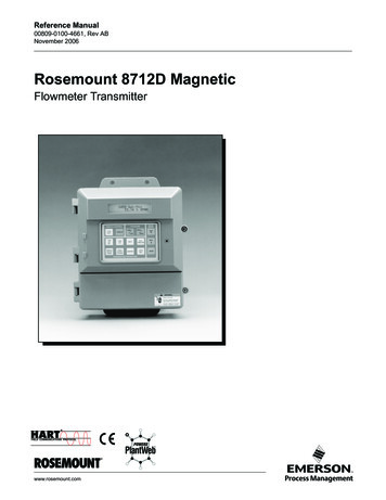
Reference Manual00809-0100-4007, Rev BCJuly 2020Rosemount 3051 Pressure Transmitterwith 4-20 mA HART Revision 5 and 7 Selectable Protocol
Safety messagesNOTICERead this manual before working with the product. For personal and system safety and for optimum product performance, ensureyou thoroughly understand the contents before installing, using, or maintaining this product.For technical assistance, contacts are listed below:Customer Central (Technical support, quoting, and order-related questions.) United States: 1-800-999-9307 (7:00 am to 7:00 pm Central Time) Asia Pacific: 65 777 8211 Europe/Middle East/Africa: 49 (8153) 9390North American Response Center (Equipment service needs.): 1-800-654-7768 (24 hours - includes Canada)Outside of these areas, contact your local Emerson representative.WARNINGExplosionsExplosions could result in death or serious injury.In an explosion-proof/flameproof installation, do not remove the transmitter covers when power is applied to the unit.Installation of device in an explosive environment must be in accordance with appropriate local, national, and internationalstandards, codes, and practices. Review the Product Certifications section of the Rosemount 3051 Product Data Sheet for anyrestrictions associated with a safe installation.Before connecting a handheld communicator in an explosive atmosphere, ensure the instruments are installed in accordancewith intrinsically safe or non-incendive field wiring practices.Process leaksProcess leaks may cause harm or result in death.Install and tighten process connectors before applying pressure.Do not attempt to loosen or remove flange bolts while the transmitter is in service.Electrical shockElectrical shock can result in death or serious injury.Avoid contact with the leads and terminals. High voltage that may be present on leads can cause electrical shock.Replacement equipmentReplacement equipment or spare parts not approved by Emerson for use as spare parts could reduce the pressure retainingcapabilities of the transmitter and may render the instrument dangerous.Use only bolts supplied or sold by Emerson as spare parts.Improper assemblyImproper assembly of manifolds to traditional flange can damage sensor module.For safe assembly of manifold to traditional flange, bolts must break back plane of flange web (i.e., bolt hole) but must notcontact sensor module housing.Severe changes in the electrical loop may inhibit HART Communication or the ability to reach alarm values. Therefore,Rosemount absolutely cannot warrant or guarantee that the correct Failure alarm level (High or Low) can be read by the hostsystem at the time of annunciation.2
WARNINGPhysical accessUnauthorized personnel may potentially cause significant damage to and/or misconfiguration of end users’ equipment. This couldbe intentional or unintentional and needs to be protected against.Physical security is an important part of any security program and fundamental to protecting your system. Restrict physical accessby unauthorized personnel to protect end users’ assets. This is true for all systems used within the facility.CAUTIONNuclear applicationsThe products described in this document are not designed for nuclear-qualified applications. Using non-nuclear qualified productsin applications that require nuclear-qualified hardware or products may cause inaccurate readings.For information on Rosemount nuclear-qualified products, contact your local Emerson Sales Representative.3
4
Reference Manual00809-0100-4007ContentsJuly 2020ContentsChapter 1Introduction. 71.1 Using this manual. 71.2 Models covered. 71.3 Product recycling/disposal.8Chapter 2Configuration. 92.1 Overview. 92.2 Safety messages. 92.3 System readiness. 102.4 Configuration basics. 112.5 Setting the loop to manual. 142.6 Verify configuration. 152.7 Basic setup of the transmitter. 162.8 Configuring the LCD display.232.9 Detailed transmitter setup.242.10 Configuring transmitter diagnostics. 312.11 Performing transmitter tests. 352.12 Configuring burst mode.372.13 Establishing multidrop communication. 39Chapter 3Hardware installation. 433.1 Overview. 433.2 Safety messages. 433.3 Considerations.443.4 Installation procedures. 46Chapter 4Electrical installation.674.1 Overview. 674.2 Safety messages. 674.3 LCD display. 684.4 Configuring transmitter security.694.5 Set transmitter alarm.724.6 Electrical considerations. 73Chapter 5Operation and maintenance.815.1 Overview. 815.2 Safety messages. 815.3 Recommended calibration tasks. 825.4 Calibration overview. 835.5 Trim the pressure signal.87Reference Manual5
ContentsJuly 2020Reference Manual00809-0100-40075.6 Trim the analog output. 89 5.7 Switching HART revision. 94Chapter 6Troubleshooting. 976.1 Overview. 976.2 Safety messages. 976.3 Troubleshooting for 4-20 mA output. 986.4 Diagnostic messages. 996.5 Disassembly procedures. 1076.6 Reassemble. 1096.7 Service support.112Chapter 7Safety Instrumented Systems (SIS) requirements. 1137.1 Identify Rosemount 3051 safety certification.1137.2 Installation in SIS applications. 1137.3 Configuring in SIS applications.1147.4 SIS operation and maintenance. 1157.5 Inspection.117Appendix AReference data. 119A.1 Ordering information, specifications, and drawings.119A.2 Product certifications. 119Appendix BField Communicator menu trees and fast keys.121B.1 Field Communicator menu trees.121B.2 Field Communicator Fast Keys. 125Appendix CLocal Operator Interface (LOI). 127C.1 LOI menu tree.127C.2 LOI menu tree - extended menu. 128C.3 Enter numbers in the LOI. 129C.4 Enter text in the LOI. 1306Rosemount 3051
Reference Manual00809-0100-4007IntroductionJuly 20201Introduction1.1Using this manualThe sections in this manual provide information on installing, operating, and maintainingthe Rosemount 3051 Pressure Transmitter. The sections are organized as follows:Configuration provides instruction on commissioning and operating the transmitters. Italso includes information on software functions, configuration parameters, and onlinevariables.Hardware installation contains mechanical installation instructions and field upgradeoptions.Electrical installation contains electrical installation instructions and field upgrade options.Operation and maintenance provides detailed information on calibrating and changingHART revisions.Troubleshooting provides troubleshooting techniques for the most common operatingproblems.Safety Instrumented Systems (SIS) requirements provides identification, installation,configuration, operation and maintenance, and inspection information for SafetyInstrumented Systems.Reference data provides information on how to access specifications, orderinginformation,and dimensional drawings.Field Communicator menu trees and fast keys provides full menu trees and abbreviatedFast Key sequences for commissioning tasks.Local Operator Interface (LOI) provides detailed LOI menu trees.1.2Models coveredThe following Rosemount 3051 Transmitters are covered by this manual: Rosemount 3051C Coplanar Pressure Transmitter— Measures differential and gage pressure up to 2000 psi (137.9 bar).— Measures absolute pressure up to 4000 psia (275.8 bar). Rosemount 3051T In-Line Pressure Transmitter— Measures absolute pressure up to 20000 psi (1378.95 bar). Rosemount 3051L Liquid Level Transmitter— Measures level and specific gravity up to 300 psi (20.7 bar). Rosemount 3051CF Series Flowmeter— Measures flow in line sizes from ½-in. (15 mm) to 96-in. (2400 mm).NoteFor transmitter with FOUNDATION Fieldbus, see Rosemount 3051 Reference Manual.Reference Manual7
IntroductionJuly 2020Reference Manual00809-0100-4007For transmitter with PROFIBUS PA, see Rosemount 3051 Reference Manual.1.3Product recycling/disposalConsider recycling equipment. Dispose of packaging in accordance with local and nationallegislations/regulations.8Rosemount 3051
Reference Manual00809-0100-4007ConfigurationJuly 20202Configuration2.1OverviewThis section contains information on commissioning and tasks that should be performedon the bench prior to installation, as well as tasks performed after installation as describedin Configuring transmitter diagnostics.This section also provides instructions on configuring with Field Communicator, AMSDevice Manager, and Local Operator Interface (LOI). For convenience, Field CommunicatorFast Key sequences are labeled Fast Keys, and abbreviated LOI menus are provided for eachfunction below.Full Field Communicator menu trees and Fast Key sequences are available in FieldCommunicator menu trees and fast keys. LOI menu trees are available in Local OperatorInterface (LOI).2.2Safety messagesProcedures and instructions in this section may require special precautions to ensure thesafety of the personnel performing the operations.WARNINGExplosionsExplosions could result in death or serious injury.Before connecting a handheld communicator in an explosive atmosphere, ensure thatthe instruments in the loop are installed in accordance with intrinsically safe or nonincendive field wiring practices.In an explosion-proof/flameproof installation, do not remove the transmitter coverswhen power is applied to the unit.Process leaksProcess leaks may cause harm or result in death.Install and tighten process connectors before applying pressure.Electrical shockElectrical shock can result in death or serious injury.Avoid contact with the leads and terminals. High voltage that may be present on leadscan cause electrical shock.Static electricityObserve safe handling precautions for static-sensitive components.Reference Manual9
ConfigurationJuly 2020Reference Manual00809-0100-4007WARNINGConduit/cable entriesUnless marked, the conduit/cable entries in the transmitter housing use a ½–14 NPTthread form. Entries marked “M20” are M20 1.5 thread form. On devices with multipleconduit entries, all entries will have the same thread form. Only use plugs, adapters,glands, or conduit with a compatible thread form when closing these entries.When installing in a hazardous location, use only appropriately listed or Ex certified plugs,glands, or adapters in cable/conduit entries.Replacement partsReplacement equipment or spare parts not approved by Emerson for use as spare partscould reduce the pressure retaining capabilities of the transmitter and may render theinstrument dangerous.Use only bolts supplied or sold by Emerson as spare parts.Improper assemblyImproper assembly of manifolds to traditional flange can damage sensor module.For safe assembly of manifold to traditional flange, bolts must break back plane offlange web (i.e., bolt hole) but must not contact sensor module housing.Severe changes in the electrical loop may inhibit HART communication or the abilityto reach alarm values. Therefore, Rosemount cannot absolutely warrant or guaranteethat the correct Failure alarm level (High or Low) can be read by the host system at thetime of annunciation.Physical accessUnauthorized personnel may potentially cause significant damage to and/ormisconfiguration of end users’ equipment. This could be intentional or unintentional andneeds to be protected against.Physical security is an important part of any security program and fundamental toprotecting your system. Restrict physical access by unauthorized personnel to protect endusers’ assets. This is true for all systems used within the facility.2.3System readiness If using HART -based control or asset management systems, confirm the HARTcapability of such systems prior to commissioning and installation. Not all systems cancommunicate with HART Revision 7 devices. For instructions on how to change the HART revision of your transmitter, see SwitchingHART revision.2.3.1Confirm correct device driver Verify the latest Device Driver (DD/DTM ) is loaded on your systems to ensure propercommunications.10Rosemount 3051
Reference Manual00809-0100-4007ConfigurationJuly 2020 Download the latest DD at Emerson.com or FieldCommGroup.org In the Browse by Member dropdown menu, select Rosemount business unit ofEmerson. Select desired product. Use the device revision numbers to find the correct Device Driver.Table 2-1: Rosemount 3051 Device Revisions and FilesReleasedateApril 2012January1998Device identificationDevice driveridentificationReviewReviewinstructions A17800809-0100 N/A-4001(1) NAMUR Revision is located on the hardware tag of the device. Differences in level 3 changes, signfied above by xx,represent minor product changes as defined per NE53. Compatibility and functionality are preserved, and you can usethe product interchangeably.(2) You can read the HART software revision with a HART capable configuration tool. Value shown is minimum revisionthat could correspond to NAMUR Revisions.(3) Device Driver file names use Device and DD Revision, e.g., 10 01. HART Protocol is designed to enable legacy devicedriver revisions to continue to communicate with new HART devices. To access new functionality, you must downloadthe new Device Driver. Emerson recommends downloading new Device Driver files to ensure full functionality.(4) HART Revision 5 and 7 selectable, power diagnostics, safety certified, LOI, process alerts, scaled variable, configurablealarms, expanded engineering units.2.4Configuration basicsCAUTIONTransmitter hardware adjustmentsSet all transmitter hardware adjustments during commissioning to avoid exposing thetransmitter electronics to the plant environment after installation.You can configure the transmitter either before or after installation. To ensure alltransmitter components are in working order prior to installation, configure thetransmitter on the bench using a Field Communicator, AMS Device Manager, or LOI. Verifythe Security switch is set in the Unlock position in order to proceed with configuration.See Figure 4-2 for switch location.2.4.1Configuring on the benchTo configure on the bench, you need a power supply and a Field Communicator, AMSDevice Manager, or LOI (option M4). Wire equipment as shown in Figure 2-1 below. Toensure successful HART Communication, verify the resistance between the transmitterReference Manual11
ConfigurationJuly 2020Reference Manual00809-0100-4007and the power supply is at least 250 Ω. See Power supply for a 4-20 mA HART for moredetails. Connect the Field Communicator to the terminals labeled COMM on the terminalblock.Figure 2-1: Wiring the TransmitterA.B.A. Vdc supplyB. RL 250 (necessary for HART Communication only)2.4.2Configuration toolsConfigure with a Field CommunicatorThere are two interfaces available with the Field Communicator: Traditional andDashboard. All steps using a Field Communicator are described using Dashboardinterfaces.Figure 2-2 shows the Device Dashboard interface. As stated in System readiness, it iscritical that the latest DD's are loaded into the Field Communicator. Visit Emerson.com orFieldCommGroup.org to download latest DD library.Field Communicator menu trees and Fast Keys are available in Field Communicator menutrees and fast keys.12Rosemount 3051
Reference Manual00809-0100-4007ConfigurationJuly 2020Figure 2-2: Device Dashboard3051 FT 45BOnline1. Overview2. Configure3. Service ToolsSAVEConfigure with AMS Device ManagerFull configuration capability with AMS Device Manager requires loading the most currentDevice Descriptor (DD) for this device.Download the latest DD at Emerson.com or FieldCommGroup.org.NoteThis manual describes all AMS Device Manager steps using version 11.5.Configure with the LOITo order the Rosemount 3051 Transmitter with the LOI, select option code M4 whenordering.To activate the LOI, push either configuration button. Configuration buttons are locatedon the LCD display (must remove housing cover to access) or underneath the top tag ofthe transmitter. See Table 2-2 for configuration button functionality and Figure 2-3 forconfiguration button location. When using the LOI for configuration, several featuresrequire multiple screens for a successful configuration. Data entered is saved on a screenby-screen basis; the LOI indicates this by flashing SAVED on the LCD display each time.LOI menu trees are available in Local Operator Interface (LOI).Reference Manual13
ConfigurationJuly 2020Reference Manual00809-0100-4007Figure 2-3: LOI Configuration ButtonsA. Internal configuration buttonsB. External configuration buttonsTable 2-2: LOI Button OperationButton2.5LeftNoScrollRightYesEnterSetting the loop to manualWhenever sending or requesting data that would disrupt the loop or change the output ofthe transmitter, set the process application loop to manual control.WARNINGExplosionsExplosions could result in death or serious injury.Before connecting a handheld communicator in an explosive atmosphere, ensure theinstruments are installed in accordance with intrinsically safe or non-incendive field wiringpractices.The Field Communicator, AMS Device Manager, or LOI will prompt you to set the loop tomanual when necessary. The prompt is only a reminder; acknowledging this prompt doesnot set the loop to manual. You must set the loop to manual control as a separateoperation.14Rosemount 3051
Reference Manual00809-0100-40072.6ConfigurationJuly 2020Verify configurationEmerson recommends that you verify various configuration parameters prior toinstallation into the process.The following sections detail the various parameters for each configuration tool.Depending on what configuration tool(s) are available, follow the steps listed relevant toeach tool.2.6.1Verify configuration with Field CommunicatorReview configuration parameters listed in Table 2-3 prior to transmitter installation. FieldCommunicator menu trees and fast keys provides a full list of configuration parametersthat can be reviewed or configured using a Field Communicator.Table 2-3 shows Fast Key sequences for the latest DD. For Fast Key sequences for legacyDDs, contact your local Emerson representative.From the HOME screen, enter the Fast Key sequences listed.Table 2-3: Device Dashboard Fast Key SequenceFunction2.6.2Fast Key sequenceHART 7HART 5Alarm and saturation levels2, 2, 2, 52, 2, 2, 5Damping2, 2, 1, 1, 52, 2, 1, 1, 5Primary variable2, 1, 1, 4, 12, 1, 1, 4, 1Range values2, 1, 1, 42, 1, 1, 4Tag2, 2, 7, 1, 12, 2, 7, 1, 1Transfer function2, 2, 1, 1, 62, 2, 1, 1, 6Units2, 2, 1, 1, 42, 2, 1, 1, 4Verify configuration with AMS Device ManagerComplete the following steps to verify the configuration parameters with the AMS DeviceManager.Procedure1. Right-click the device and select Configuration Properties from the menu.2. Navigate the tabs to review the transmitter configuration data.2.6.3Verify configuration with LOIComplete the following steps to verify configuration parameters with the LOI.Procedure1. Press any configuration button to activate the LOI.Reference Manual15
ConfigurationJuly 2020Reference Manual00809-0100-40072. Select VIEW CONFIG to review the below parameters.3. Use the configuration buttons to navigate through the menu.The parameters you need to review prior to installation include: Tag Units Transfer Function Alarm and Saturation Levels Primary Variable Range Values Damping2.6.4Verifying process variables configurationThis section describes how to verify that you selected the correct process variables.Verify process variables with a Field CommunicatorFrom the HOME screen, enter the Fast Key sequence:Device Dashboard Fast Keys3, 2, 1Verify process variables with AMS Device ManagerComplete the following steps to verify process variables with AMS Device Manager.Procedure1. Right-click the device and select Overview from the menu.2. Select the All Variables button to display the primary, secondary, tertiary, andquaternary variables.2.7Basic setup of the transmitterThis section goes through the necessary steps for basic setup of a pressure transmitter.When installing in DP level or DP flow applications, refer to Configuring scaled variable forsetup instructions.16Rosemount 3051
Reference Manual00809-0100-40072.7.1ConfigurationJuly 2020Setting pressure unitsWARNINGSpare partsReplacement equipment or spare parts not approved by Emerson for use as spare partscould reduce the pressure retaining capabilities of the transmitter and may render theinstrument dangerous.Use only bolts supplied or sold by Emerson as spare parts.The pressure unit command sets the unit of measure for the reported pressure.Set pressure units with a Field CommunicatorFrom the HOME screen, enter the Fast Key sequence.Device Dashboard Fast Keys2, 2, 1, 1, 4Set pressure units with AMS Device ManagerComplete the following steps to set pressure units with AMS Device Manager.Procedure1. Right-click the device and select Configure.2. Select Manual Setup and select desired units from the Pressure Units dropdownmenu.3. Select Send when complete.Set pressure units with the LOIComplete the following steps to select pressure units with the LOI.Procedure1. Follow Figure 2-4 to select desired pressure and temperature units. Go to UNITS PRESS UNITS.Reference Manual17
ConfigurationJuly 2020Reference Manual00809-0100-4007Figure 2-4: Selecting Pressure Units with LOIVIEW CONFIGZERO TRIMUNITSRERANGELOOP TESTDISPLAYEXTENDED MENUEXIT MENUUNITSPRESS UNITSTEMP UNITSBACK TO MENUEXIT MENUPRESS UNITSINH2OMMHGCMHG0CMHG0CPSIPSFATMTORRPAKPA.2. Use the SCROLL and ENTER buttons to select desired unit.3. Save by selecting SAVE as indicated on the LCD display screen.2.7.2Setting transmitter output (transfer function)The transmitter has two output settings: Linear and Square root.As shown in Figure 2-6, activating the square root options makes analog outputproportional to flow and includes a fixed Low Flow Cutoff at five percent.However, Emerson recommends using scaled variable for Differential Pressure (DP) Flowand DP Level applications. Refer to Configuring scaled variable for setup instructions.Set transmitter output with a Field CommunicatorFrom the HOME screen, enter the Fast Key sequence.Device Dashboard Fast Keys2, 2, 1, 1, 6Set transmitter output with AMS Device ManagerComplete the following steps to set transmitter output with AMS Device Manager.Procedure1. Right-click the device and select Configure.2. Select Manual Setup, select output type from Analog Output Transfer Function,and click Send.3. Carefully read the warning and select Yes if it is safe to apply the changes.Set transmitter output with the LOIReference Figure 2-5 to select either linear or square root transfer function using the LOI.Go to EXTENDED MENU TRANSFER FUNCT.18Rosemount 3051
Reference Manual00809-0100-4007ConfigurationJuly 2020Figure 2-5: Set Transmitter Output with LOIVIEW CONFIGZERO TRIMUNITSRERANGELOOP TESTDISPLAYEXTENDED MENUEXIT MENUEXTENDED MENUCALIBRATDAMPINGTRANSFER FUNCTSCALED VARIABASSIGN PVTAGALARM SATVALUESPASSWORDSIMLATEHART REVBACK TO MENUEXIT MENUTRANSFER FUNCTLINEAR TRANSFERFUNCTIONSQR ROOT TRANSFERFUNCTIONBACK TO MENUEXIT MENUFigure 2-6: 4-20 mA HART Square Root Output Transition Point20mAAAB4 mACB0102030405060708090100% Pressure Input4 mA00.51% Pressure InputA. Square root curveB. 5% transition pointC. 4% transition point2.7.3Rerange the transmitterThe range values command sets each of the
Fieldbus, see Rosemount 3051 Reference Manual. Reference Manual Introduction 00809-0100-4007 July 2020. Reference Manual 7. Reference Manual. Configuration. Hardware installation. Electrical installation. Operation and maintenance. Troubleshooting. Safety Instrumented Systems \(SIS\) requirements. Reference data. Field Communicator menu trees .