Transcription
AlGaN/GaN HEMTs: An overview of device operation and applicationsU.K. MishraElectrical & Computer Engineering Department, Engineering I, University of California, Santa Barbara,Santa Barbara, California 93106P. Parikh, Y.F. WuCree Lighting Company, 340 Storke Road, Goleta, California, 931171
Abstract:Wide band gap semiconductors (as evidenced by this issue) are extremely attractive forthe gamut of power electronics applications from power conditioning to microwave transmittersfor communications and RADAR. Of the various materials and device technologies, theAlGaN/GaN HEMT seems the most promising. This paper attempts to present the status of thetechnology and the market with a view of highlighting both the progress and the remainingproblems.Introduction and Market Analysis:As the market for cellular, personal communications services, broadband access areexpanding and third-generation (3G) mobile systems coming closer to reality, RF & Microwavepower amplifiers are beginning to be the focus of attention. Variety of power amplifiertechnologies are vying for market share like Si-LDMOS (Lateral-diffused MOS) and Bipolartransistors, GaAs MESFETs, GaAs (or GaAs/InGaP) heterojunction bipolar transistors (HBTs),SiC (Silicon Carbide) MESFETs and GaN HEMTs.The materials properties of GaN compared to the competing materials is presented inTable 1. The resulting competitive advantages of GaN devices and amplifiers for a commercialproduct are described in Table 2. The first column states the required performance benchmarksfor any technology for power devices and the second column lists the enabling feature of GaNbased devices that fulfill this need. In every single category, GaN devices excel overconventional technology. The last column summarizes the resulting performance advantages atthe system level and to the customer. The highlighted features offer the most significant productbenefits. The high power per unit width translates into smaller devices that are not only easier tofabricate but also offer much higher impedance. This makes it much easier to match them to the2
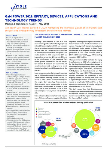
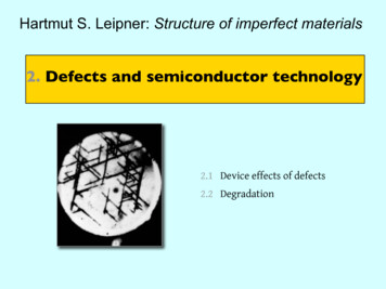
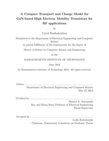
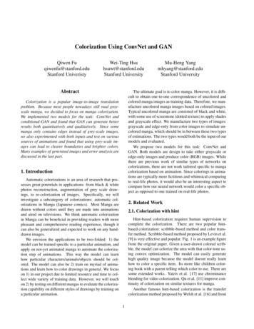
system, which is often a complex task with conventional devices in GaAs (for e.g. a matchingratio 10 times larger might be needed for a GaAs transistor, increasing overall complexity andcost). The high voltage feature eliminates or at least reduces the need for voltage conversion.Commercial systems (e.g. Wireless Base Station) operate at 28 Volts and a low voltagetechnology would need voltage step down from 28 V to the required voltage. However, GaNdevices can easily operate at 28 V and potentially up to 42 Volts. The higher efficiency thatresults from this high operating voltage reduces power requirements and simplifies cooling, animportant advantage, since cost and weight of cooling systems is a significant fraction of the costof a high power microwave transmitter. The Nitride technology is also the critical enabler forblue, green and white lighting. The commercial lighting market is a multi-billion dollar market.While some of the requirements for RF and Microwave applications are different (such as theneed for a Semi Insulating substrate), there is no doubt that exercising overlapping technologieswill contribute in driving the development cost down of RF components and offer leverage up toa certain extent.The rate of progress in the power density and total power available from AlGaN/GaNHEMTs has been remarkable as shown in Fig. 1. This has increased confidence in consideringGaN HEMTs for commercial and DoD applications, sooner rather than later. GaN HEMTs havedemonstrated one-order higher power density and higher efficiency over the existingtechnologies- Silicon and Gallium Arsenide-based RF and microwave transistors. Thus for thesame output power, a 10-x reduction in device size can be realized using GaN-based devices inplace of conventional devices. The schematic of Fig. 2 illustrates this case where a complexmodule can potentially be replaced by a smaller module utilizing GaN. In this case, having3
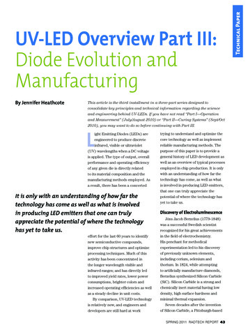
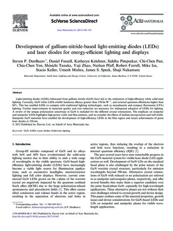
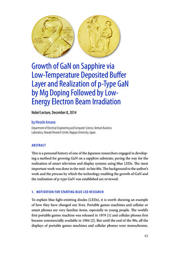
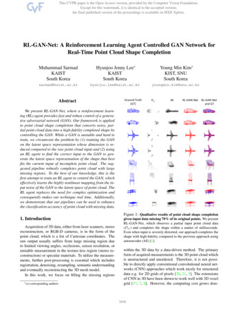
higher power per unit die of GaN would not only translate to lower chip costs but also contributeto reduced system costs by reducing/eliminating power combining.The above technological advantages result from the combination of the wide-band gap ofGaN and the availability of the AlGaN/GaN heterostructure where high voltage, high current andlow on-resistance can be simultaneously achieved, resulting in high power-high efficiencyoperation. Furthermore, the wide-bandgap offers a rugged and reliable technology capable ofhigh voltage-high temperature operation. This opens up several industrial, automotive andaircraft applications like power and high voltage rectifiers and converters. Some of thecommercial and military markets that can be targeted by GaN are shown in Fig. 3.According to a recent survey by Strategies Unlimited, the total GaN Electronic Devicemarket is expected to reach 500 M by the end of this decade. RF and microwave applicationsare likely to be the largest share of the GaN device market. The GaN HEMT targets both militaryand commercial applications. The former include RADARs (ship-board, airborne and ground)and high performance space electronics. The latter include: base station transmitters, C-bandSatcom, Ku-K band VSAT and broadband satellites, LMDS and digital radio.Device Structure and Materials Issues:Figure 4 shows the structure of a basic HEMT. The lack of a Gallium Nitride substratenecessitates heteroepitaxy on compatible substrates, commonly sapphire and Silicon Carbide, butAluminum Nitride, Silicon and complex oxides such as Lithium Gallate may also emerge asviable. The epitaxial layers may be either grown entirely by MBE or MOCVD or on a resistiveGaN buffer grown by VPE, though the latter, currently, is less common. Heteroepitaxy on suchseverely lattice-mismatched substrates makes the nucleation layer one of the most critical aspectsof the growth. With sapphire as a substrate, the nucleation layer consists of GaN or AlN4
deposited at a low temperature (typically 600 C), which is then heated up to the growthtemperature of the main layer.1 The GaN and AlGaN layers are typically grown at 1000 C atgrowth rates of 1µ m / hr. Nucleation on SiC is typically performed using AlN grown at 900 C. 2A physical effect that dominates device behavior and may also determine defect densityin the film is the polar nature of the GaN and AlGaN. Figure 5 shows the crystal structure of Gapolarity or Ga-face GaN. Currently all high quality material is grown with this polarity. Thesense of the spontaneous polarization is indicated on the diagram. The band diagram and piezoelectric constants versus lattice constant for the (Al, Ga, In, N) system is shown in Fig. 6. Thetensile strain caused by the growth of AlxGa1-xN on GaN results in a piezoelectric polarization,Ppz, that adds to the net spontaneous polarization, Psp, in a manner given by the equation below3:P( x) Ppz Psp ( 3 2 x 1 9 x 2 ) x 10 6 x 5 2 x 10 x Ccm 2 where P(x) is the net total 6polarization. This results in a net positive charge at the AlGaN/GaN interface as shown in Fig.7a. The compressive strain caused by the growth of InxGa1-xN on GaN causes a net negativepiezoelectric polarization charge at the InxGa1-xN-GaN interface as shown in Fig. 7b. Themagnitude of the charge follows the equation shown below3:P( x) Ppz Psp (14 1x 4 9 x 2 ) x 10 6 ( 0 3 x 10 6 ) x Ccm 2The built-in polarization dipole can have a maximum moment, approximately equal to Ev Eg ,GaN as apparent from the band-diagram in Fig. 8a. The charge distribution is thencomposed of the polarization dipole Qπ and an opposing dipole comprising of a surface holegas, ps, and a 2DEG at the heterointerface, ns. In practice, experiments4 have shown that the2DEG is induced before a surface hole gas formation by the ionization of a deep surface donor5
resulting in a charge distribution, shown in Fig. 8b. Here the polarization dipole is screened bythe positively charged surface donor (of depthEDD and concentration N DD ) and the 2DEG.Device Fabrication and Performance:Device fabrication of the AlGaN/GaN HEMT (shown in Fig. 4) commences with thedefinition of the active device area. This can be either determined by Cl2 mesa etching5 or by theion implantation6. Next, the ohmic contacts are formed by first, partially etching the AlGaN inthe source and drain regions, depositing the ohmic metals and annealing at 900 C. ThoughTi/Al/Ni/Au has been the preferred metallurgy7, Ta-based ohmic contacts 8 are now beinginvestigated for their improved morphology. Next, the gate is defined by lift-off of Ni/Aumetallurgy. The efficacy of a gate recess which is commonly employed in compoundsemiconductor technology is currently being investigated in the GaN system9. Device fabricationis completed with a deposition of a SiN passivation layer. This layer serves a critical purpose ineliminating dispersion between the large signal AC and the DC characteristics of the HEMT. Theeffect is illustrated in Fig. 9 where the AC curve is obtained by biasing the device into pinch-offand trying to recover the full channel current by pulsing the gate on by utilizing a 80 µs gatepulse on a curve tracer. The maximum AC current is less than the DC current, the differencebeing referred to as dispersion. This effect can be explained (though alternate plausibleexplanations are currently being discussed10) by the mechanism depicted in Fig. 10. When thedevice is biased into pinch-off, electrons from the gate are injected into the empty surface donorsrequired to maintain a 2DEG. Compensation of these donors reduces the 2DEG. Under AC drivethe electrons cannot respond because of the long time constant of the donor traps, resulting in areduced channel current and higher on resistance (symptoms of dispersion). SiN passivationeliminates this effect as shown in Fig. 11, though the exact mechanism is under debate.6
Device and Circuit Performance:Typically AlGaN/GaN HEMTs have demonstrated high power densities of 6-9 W/mmboth on sapphire and SiC substrates 11, 12, 13, approaching a one-order improvement overconventional HEMTs and confirming the extremely great potential of this device technologypredicted by theory. However, these power density values were generally achieved under highgain compression of 5-9 dB, which is an indication of undesired non-linearity. This phenomenoncan be explained by traps, although largely reduced, still existing in these devices. Recently,effort in pursuing higher quality epi-layers of the AlGaN/GaN HEMTs has resulted in significantimprovement of the large-signal characteristics. These devices were grown by metal-organicchemical-vapor deposition on semi-insulating SiC substrates. The epi-layers consisted of aninsulating GaN buffer and a lightly-doped AlGaN layer to supply charge for the 2-dimensionalgas as well as to serve as a Schottky-gate barrier. The Al composition was greater than 30%.Special attention was paid to ensure high crystal quality of all the epi-layers. Typical mobilitywas improved to 1500 cm2/V-s from previous values around 1200 cm2/V-s simultaneously witha high 2-DEG density of 1-1.2x1013 cm-2. The gate-length was 0.6 µm obtained by opticalstepper lithography. The gate width was 2 x 150 µm, or 300 µm, with a U-shape layout.The devices showed an on-resistance of 2.5 Ω-mm (after subtraction of the resistance dueto the wire and probes) and a current density of 1 A/mm. The breakdown voltage was 80 V.The current-gain and power gain cutoff frequencies were 25 GHz and 60 GHz respectively. AnATN load-pull system was used for large-signal characterization at 8 GHz. Fig. 12 shows the onwafer measurement result of a 300-µm-wide device when tuned for power. A power density of10.3 W/mm was achieved along with 42 % power added efficiency (PAE). This increased powerdensity was obtained at a reduced gain compression of 3.4 dB, which is attributed to reduction of7
trapping effect due to improved epi quality and surface passivation. Since the trapping effectdeteriorates with increased electric field or bias voltage for a specific device dimension,performance of the devices as a function of bias voltage can be used as a valid measure of thisphenomenon. Fig. 13 shows the measurement results of the AlGaN/GaN HEMTs under a widevoltage bias range from 10 V to 40 V, where the tuning was for optimum efficiency. It is seenthat a relatively flat PAE plateau of 56-62% was achieved throughout the wide voltage span,illustrating flexibility of power-supply requirement for various applications. Simultaneouslyhigh power density of 8.3 W/mm and PAE of 57 % were obtained at 40-V bias. The ability toachieve a high PAE at such a high bias voltage confirms the reduction of trapping effect withthese devices. Obtaining a high PAE simultaneously with high power is essential for systeminsertion since dealing with the heat generated in inefficient amplifiers could be prohibitivelydifficult.GaN-Based AmplifiersThe design of a GaN-based power amplifier is significantly different from theconventional GaAs-based one in a sense that both the input and output impedance transformationratios are drastically reduced for the same output power rating. With a gate length of 0.6 µm,maximum drain current of 1 A/mm and a breakdown voltage of 80 V, an AlGaN/GaN HEMTtypically shows an input capacitance of 2.7 pF/mm, similar to that of a GaAs-based HEMT whilethe optimum output load is 75Ω mm, about 2 times that of a GaAs HEMT. Since the GaNHEMT offers 10 times the power density, for the same output power, the input transformationratio is 10x less while the output is 20x less than a GaAs HEMT. For high power amplifierswhere multi-millimeter to centimeter gate peripheries are needed, this reduction in impedancetransformation translates to great circuit matching simplicity. Another design difference lies in8
the high operation voltage of these devices, which requires higher voltage ratings of the on-chipcapacitors.A C-band power amplifier is illustrated below to show the benefit of using theAlGaN/GaN HEMT. Taking into account device non-uniformity, drive non-uniformity andcircuit loss, a total gate periphery of 8-mm was chosen to achieve a design goal of 50 W output.At the input, a C-L-C-R network was used to convert the capacitive gate impedance to a realvalue of about 1.5 Ω within the bandwidth. This was then transformed to the 50-Ω inputimpedance by a multiple π network. At the output, the power load for the 8-mm-wide device wasabout 7.5 W (assuming a bias of 35 V and a knee voltage of 5 V), which was transformed to the50-W circuit output. The circuit was laid out in a co-planar-wave (CPW) transmission linesystem and constructed using a flip-chip IC scheme (FC-IC). The circuit substrate was AlN, onwhich all Metal-Insulator-Metal (MIM) capacitors, metal resistors and air-bridge interconnectswere fabricated as integrated components. The devices were diced and flip-chip bonded on to thecircuit substrates for optimum electrical and thermal interfacing. The finished FC-IC amplifier isshown in Fig. 14. The output characteristics of the device are shown in Fig. 15. The maximumcurrent of 8 A indicates satisfactory electrical scaling, which is crucial for achieving desiredoutput power. The amplifier exhibited a mid-band small signal gain 14.5 dB when biased above25 V, close to the simulation result of 16 dB. Pulsed power measurement was performed using0.5-mS pulse width and 5% duty cycle. The output power at 6 GHz was 35 W when biased at 29V, which increased to 49 W at 38 V. At 39 V, an output power of 51 W at 6 GHz was recordedas shown in Fig. 16. This represents a remarkable power level for a solid-state FET with a gatewidth of only 8-mm. The corresponding power density was 6.4 W/mm. For the same outputvalue, in the conventional GaAs-based FET technology, either a HEMT or a MESFET, the9
device gate periphery would have been 80 mm and require a challenging input impedancetransformation from 0.15 Ω to 50 Ω!Summary and Conclusions:While the GaN device and circuit technology is likely poised to break out in thecommercial arena, certain risks or barriers to entry in the market should not be overlooked. Therelative technology immaturity of GaN with respect to Silicon and GaAs leave issues like longterm reliability unanswered. The market pull in the acceptance of a new technology might beweak. For example, it might be difficult to get into the design cycles of some of the products like3G Base Station amplifiers early enough to be the technology of choice when these systems areeventually deployed. Finally, the relative high initial cost will continue to be an issue. Most ofthe promising results for GaN have been achieved on S.I SiC substrates, which are currentlycommercially available only at 2” diameter. However, wafer vendors are aggressively workingon higher diameter wafers.With all of these in mind, the overall performance advantages for early insertion of GaN willhave to be compelling to justify the higher cost product. Initially, GaN will be a replacementtechnology and vie to take markets from existing technologies including existing solid state Siand GaAs based solutions, as well as high power microwave vacuum tubes. Ultimately, thecompact size of GaN-based transistors will lead to lower cost products. This will increasesystem efficiency, reduce system costs, and will expand the market applications.Acknowledgements:The work at UCSB and CREE Lighting Company has been supported by ONR, AFOSR,DARPA, BMDO, and the SBIR programs. Special thanks to Dr. Stacia Keller, Professor S.10
DenBaars, and Professor J. Speck and all our students and colleagues who made the progresspossible.11
Table Titles:Table 1.Table of Properties of Competing Materials in Power ElectronicsTable 2.Competitive Advantages of GaN Devices12
Figure Captions:Fig. 1.Historical progress in GaN transistor technology.Fig. 2.Schematic comparison illustrating advantages of GaN over existing technology.Fig. 3.Applications for GaN HEMTs.Fig. 4.Basic HEMT structure.Fig. 5.Crystal Structure of Ga-polarity or Ga-face GaN.Fig. 6.Band diagram and piezoelectric polarization versus the lattice constant for the (Al, Ga,In, N) system.Fig. 7a. The net positive charge at the AlGaN/GaN interface caused by the sum of the netspontaneous polarization and piezoelectric polarization between AlGaN and GaN.Fig. 7b. The net negative charge at the In GaN-GaN interface caused by the compressive strainresulting from growth of InxGa1-xN on GaN.Fig. 8a. Band diagram of the AlGaN-GaN HEMT if the polarization dipole is partiallyterminated by a surface hole gas.Fig. 8b. Band diagram of the AlGaN-GaN HEMT if the polarization dipole is partiallyterminated by a surface deep donor.Fig. 9.Dispersion between the large signal AC and DC HEMT characteristics simulated by a80 µs pulse on the gate.Fig. 10. Proposed mechanism for large signal dispersion; occupancy of surface traps undernegative bias.Fig. 11. SiN passivation eliminating reduced channel current and higher on resistance(symptoms of dispersion).13
Fig. 12. Power performance of a 300-µm-wide AlGaN/GaN HEMT, showing 10.3 W/mmpower density, the highest for any FET of the same size. Gain compression was –3.4dB; drain bias was 45 V. Device dimension: 300x0.6 mm2.Fig. 13. Family of power sweeps at 8 GHz with biases of 10, 15, 20, 25, 30, 35, 40 V. Arelatively flat PAE plateau of 56-62% was achieved through out the wide voltage span.Device dimension: 300x0.6 mm2. Tuning was performed at 35 V for optimum PAE.Fig. 14. Photo of a 50-W GaN-based Flip-Chip Amplifier IC incorporating a 8-mmAlGaN/GaN HEMT. The circuit size is about 10mm x 7mm.Fig. 15. I-V characteristics of the 8-mm AlGaN/GaN HEMT, showing a maximum current levelof 8 A. Most of the apparent on-resistance was due to the resistance of wire and probesFig. 16. Power sweep of the GaN FC-IC at 6 GHz, showing a peak output of 47.1 dB, or 51 W,the highest achieved for an 8-mm solid-state FET to date14
[1]H. Amano, N. Sawaki, I. Akasaki, Y. Toyoda, “Metalorganic vapor phase epitaxialgrowth of high quality GaN film using an AlN buffer layer”, Appl. Phys. Lett., vol. 48,no. 5, p. 353-5, Feb. 1986.[2]T.W. Weeks, Jr. M.D. Bremser, K.S. Ailey, E. Carlson, W.G. Perry, R.F. Davis, “GaNthin films deposited via organometallic vapor phase epitaxy on alpha (6H)-SiC(0001)using high-temperature monocrystalline AlN buffer layers, Appl. Phys. Lett. 67, pp. 401403, July 1995.[3]O. Ambacher, J. Smart, J.R. Shealy, N.G. Weimann, K. Chu, M. Murphy, W.J. Schaff,LF. Eastman, R. Dimitrov, L. Wittmer, M. Stutzman, W. Rieger, and J. Hilsenbeck, J.Appl. Phys. 85, 3222 (1999).[4]R. Vetury, N.-Q. Zhang, S. Keller, U.K. Mishra, “The impact of surface states on the DCand RF characteristics of AlGaN/GaN HFETs,” IEEE Trans. Elect. Dev, vol. 48, no. 3,pp. 560-566, 2001.[5]S. J. Pearton, J. C. Zolper, R. J. Shul, F. Ren, “GaN: processing, defects, and devices”,Journal of Applied Physics, vol.86, (no.1), AIP, 1 July 1999. p.1-78.[6]S. C. Binari, H. B. Dietrich, G. Kelner, L. B. Rowland, K. Doverspike, D. K. Wickenden,“H, He, and N implant isolation of n-type GaN”, Journal of Applied Physics, vol.78,(no.5), 1 Sept. 1995. p.3008-11.[7]Z. Fan, S. N. Mohammand, W. Kim, O. Aktas, A. E. Botchkarev, and H. Morkoc, “Verylow resistance ohmic contact to n-GaN”, Appl. Phys. Lett. 68 (12), pp. 1672-1674, 18March 1996.15
[8]D. Qiao, L. Jia, L. S. Yu, P. M. Asbeck, S. S. Lau, S.-H Lim, Z. Liliental-Weber, T. E.Haynes, J. B. Barner, “Ta-based interface ohmic contacts to AlGaN/GaNheterostructures” Journal of Applied Physics, vol.89, (no.10), 15 May 2001. p.5543-6.[9]D. Buttari, A. Chini, G. Meneghesso, E. Zanoni, P. Chavarkar, R. Coffie, N.Q. Zhang, S.Heikman, L. Shen, H. Xing, C. Zheng, and U.K. Mishra, “Systematic characterization ofCl2 reactive ion etching for gate recessing in AlGaN/GaN HEMTs,” Submitted to IEEEElectron Device Letters.[10]A. Khan, 2nd GaN Electronics Workshop, Santa Barbara, CA, 2000.[11]S Keller, Y.-F. Wu, G. Parish, N. Zhang, J. J. Xu, B. P. Keller, S. P. DenBaars and U. K.Mishra, “Gallium nitride based high power heterojunction field effect transistor : Processdevelopment and present status at UCSB”, IEEE Transaction on Electron Devices, pp.552-559,Vol. 48, No. 3, March 2001.[12]S.T. Sheppard, K. Doverspike, W.L. Pribble, S.T. Allen and J.W. Palmour, “High PowerMicrowave GaN/AlGaN HEMTs on Silicon Carbide”, IEEE Electron Device Lett., Vol.20, No. 4, pp. 161-163, April 1999.[13]Y.-F. Wu D. Kapolnek, J.P. Ibbetson, P. Parikh, B.P. Keller and U. K. Mishra, “Veryhigh power density AlGaN/GaN HEMTs”, IEEE Transaction on Electron Devices, pp586-590,Vol. 48, No. 3, March 2001.16
Table 1µεEgBFOMRatioJFMRatioTmaxSi130011.41.11.01.0300 CGaAs500013.11.49.63.5300 CSiC2609.72.93.160600 CGaN15009.53.424.680700 CMaterialBFOM Baliga’s figure of merit for power transistor performance [K*µ*Ec3]JFM Johnson’s figure of merit for power transistor performance(Breakdown, electron velocity product) [Eb*Vbr/2π]
Table 2NeedEnabling Feature Performance AdvantageHigh Power/Unit WidthWide Bandgap, High FieldCompact, Ease of MatchingHigh Voltage OperationHigh Breakdown FieldEliminate/Reduce Step DownHigh LinearityHEMT TopologyOptimum Band AllocationHigh FrequencyHigh Electron VelocityBandwidth, µ-Wave/mm-WaveHigh EfficiencyHigh Operating VoltagePower Saving, ReducedCoolingLow NoiseHigh gain, high velocityHigh dynamic range receiversHigh TemperatureOperationWide BandgapRugged, Reliable,Reduced CoolingThermalManagementSiC SubstrateHigh power devices withreduced cooling needsTechnologyLeverageDirect Bandgap:Enabler for LightingDriving Force for Technology:Low Cost
Fig 111CornellTotal power10Cree509Total power (W)UCSB8CREECree76UCSB543CornellHRLEPl aray lyersPower density (W/mm)Cree60Power density40HRL20201996CREE3010CreelyEar 00Year19982000UCSB02002Year Includes ALL LEADING players in the field CREE Cree Lighting CreeCree-Durham2002
Fig 2 10-x power density ( 10 W/mm) 10-x reduction in power-combiningOUTIN Improved efficiency ( 60 %) Improved reliability Compact sizeGaAs High PowerAmplifier Module Superior Performance at reduced costINOUTEquivalentHigh PowerGaN AmplifierModule
Fig rd Radar,DD21RadarSatcomSatcomBaseStation MMDS,Driver WLL3GAmpUNIIHiperlanVSATLMDSMVDSDigitalRadio0.1S CXKu10 GHz2 GHzBATP31MissileSeekersCARKKa Q V W60 GHz30 GHzFrequency Band
Fig 4SiN yerGaN, AlGaN or AlNSubstrate: Typically Sapphire or SiC
Fig 5
Fig 6
Fig 7a Qπ , AlGaNQπ , AlGaNAlxGa1-x N GaN () P( x ) Qπ , AlGaN ( Qπ ,GaN ) Qπ , GaNQπ , GaNQπ includes the contribution of spontaneous and piezo-electric contributions
Fig 7b Qπ , InGaN Qπ , InGaN( Qπ , GaN )P( x ) Qπ ,GaN ( Qπ ,InGaN )InxGa1-xNQπ , GaNQπ includes the contribution of spontaneous and piezo-electric contributions
Fig 8aVA l GaN ! Eg ,GaN Ev Maximum Dipole MomentGaNAlGaNEg , GaN Evps Qπ (cm 2 )Qπ (cm 2 )ns
Fig 8bEDDAlGaN N DD QπGaNQπ (cm 2 )nsEF
Fig 9DCId (5 mA)DispersionACLoad lineVds (V)
Fig 10LgSourceElectrons inSurface StatesGATEDrainAlGaNGaNDepletion of 2DEGcaused by occupiedsurface states
Fig 11
Fig 00051015P in (dB)202530I d (mA)P out (dB), Gain(dB), PAE (%)45P out 10.3 W/mmPAE 42%41.6%f 8GHz,Tuned for Power
Fig 13Poutf 8GHz7060850740Pout (W/mm)963052041030Increasing Vds2-101-200-30-50510Pin (dB)152025PAE (%)PAE;10
Fig 14
Fig 15Id (A/divsion)Vg start: 2V, Step: -2 VVds (V/divsion)
Fig 1650G ainDEPAEPo u t3545304025352030152510205150101822263034Pin (dBm)3842Pout (dBm)Gain (dB), DE(%), PAE(%)40
aircraft applications like power and high voltage rectifiers and converters. Some of the commercial and military markets that can be targeted by GaN are shown in Fig. 3. According to a recent survey by Strategies Unlimited, the total GaN Electronic Device market is expected to reach 500 M by the end of this decade. RF and microwave applications