Transcription
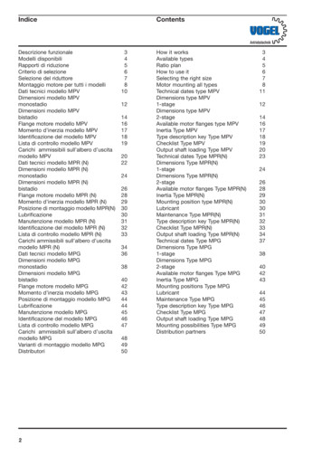
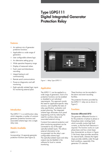
Type LGPG111Digital Integrated GeneratorProtection RelayFeatures An optimum mix of generatorprotection functions Applicable to a wide range ofgenerators User configurable scheme logic An alternative setting group Wide operative frequency range Display of measured values Fault, event and disturbancerecording Integral testing to aidcommissioning Remote serial communications Power-on diagnostics and selfmonitoring Eight optically isolated logic inputsfor monitoring external plant.IntroductionThe LGPG111 is a multi-function relaywhich integrates a number of commongenerator protection functions andassociated scheme logic into a singlerelay case.Models AvailableLGPG111Incorporating 14 separate generatorprotection functions (see Figure 2).2Figure 1: Relay Type LGPG111ApplicationThe LGPG111 can be applied to awide range of generators. Each of itsprotection functions can be enabledor disabled to suit individualrequirements. This approach avoidsthe need for application-specific relayversions, and simplifies the tasks ofrelay specification, evaluation andproject planning. The integratedscheme logic eliminates much panelengineering work by reducing theneed for auxiliary relays andassociated external wiring.Contacts from external protection andplant monitoring equipment can beconnected to any of the eightoptically-isolated inputs. This allowsexternal information to beincorporated into the relay’s userconfigurable scheme logic.The optically-isolated inputs and relayoutputs may be labelled in thesoftware for local or remotemonitoring.These functions can be recorded inthe alarm and event recordingfacilities.The protection functions provided bythe LGPG111 relay are as shown inFigure 2.FunctionsGenerator differential (87G)The generator differential function isfor the protection of phase to phase orthree-phase stator windings faultswhich normally involve high faultcurrents, so that fast fault clearance isrequired. This function works on a perphase basis and has a dual slopebias characteristic as shown in Figure3: the lower slope provides sensitivityfor internal faults, whereas the higherslope provides stability under throughfault conditions, especially if thegenerator CTs saturate.
Stator earth fault (51N)The stator earth fault function iscurrent operated and can be typicallyset to cover up to 95% of the statorwindings. It is generally used onresistively earthed generators, but canalso be used to respond to current inthe secondary circuit of an earthingtransformer loaded with a resistor.A time-delayed low set element andan instantaneous high set element areprovided.Neutral displacement (59N)The neutral displacement function isvoltage operated and is used fordetecting stator winding earth faultson generators which are earthed viaa distribution transformer. Two timeroutput elements are provided.Sensitive directional earth fault (67N)When two or more generators areconnected in parallel directly to abusbar, the sensitive directional earthfault function is used to discriminatebetween internal and external earthfaults. A dedicated single-phase CTinput is available for the operatingcurrent, which can accept the residualcurrent from three line CTs or currentfrom a dedicated core-balance CT.The polarising signal for thedirectional decision is either thevoltage signal applied to the neutralvoltage VT input or the current signalapplied to the stator earth fault currentinput.The stator earth fault, neutraldisplacement and sensitive directionalearth fault functions all have thirdharmonic rejection built in by meansof a software filter.Voltage dependent overcurrent (51V)The voltage dependent overcurrentfunction is used for system backupprotection and can trip the generatorcircuit breaker, if a fault has not beencleared by other protection after acertain period of time. The voltagedependent function can be eithervoltage controlled or voltagerestrained.When voltage controlled, the timingcharacteristic is changed from a loadto a fault characteristic when thevoltage drops below a set level. It ismainly used for generators connecteddirectly to the busbar.87GGenerator differential51N59NStator earth faultNeutral displacement67NSensitive directional earth fault51V32RVoltage dependent overcurrentReverse power32L46Low forward powerNegative phase sequence40Field failure2759Under voltageOver voltage60Under frequencyOver frequency60Voltage gure 2: Protection functions provided by LGPG111DifferentialcurrentTripIs1Percentagebias K2Percentagebias K1No TripIs2Maximum mean bias currentFigure 3: Generator differential bias characteristicCurrentpick-uplevelI Currentpick-uplevelI KI KI VsVoltagelevelVs2Voltage controlled modeVs1VoltagelevelVoltage restrained modeFigure 4: Voltage dependent overcurrent functionsWhen voltage restrained, the currentpick-up level is proportionally loweredas the voltage falls below a set value,producing a continuous variation oftiming characteristics. This isapplicable to generators connected tothe busbar, each via a step-uptransformer.A voltage vector compensation featureis also available to determine the HVphase-phase voltage signals where aYd1 or a Yd11 step-up transformer isused.The timing characteristic can either bedefinite time or IDMT.The effects of the voltage level on thecurrent pick-up level for both functionsare shown in Figure 4.3
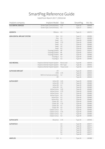
Reverse power (32R) and low forwardpower (32L)Reverse power protection is used todetect loss of the prime mover.Low forward power protection can beapplied to steam turbine generatorswhere sequential shutdown ispreferable, under less urgentoperations, to avoid over-speeding.Both are balanced conditions,therefore a single phase measurementis sufficient. For this function, the relaycalculates VIcosθ for the A-phase.In order to provide the requiredsensitivity, a special current input isused for both of these functions.A compensation angle setting is alsoavailable to compensate for phaseerror of the generator’s CT and VTsignals. A delayed drop-off timer isincluded in the timing logic which actsas an integrating timer. This allowsthe relay to trip within the predetermined time delay, underpulsating power conditions.ttMAXKtminI2 I2Figure 5: Negative phase sequence tripping characteristicXR–XaNegative phase sequence (46)Negative phase sequence function isfor the detection of sustainedunbalanced load conditions.Under such circumstances doublefrequency eddy currents are inducedin the rotor of a generator and cancause rapid overheating. The functionhas a thermal replica curve whichsimulates the effects of pre-faultheating due to low levels of standingnegative phase sequence current I2.When the I2 value is well abovethreshold, the thermal replicaapproximates to at K/I22 characteristic, where K isthe generator’s per-unit currentthermal capacity constant in seconds.The tripping characteristic is shown inFigure 5.When high values of K are selectedand the negative phase sequencecurrents measured are near to thethreshold, the operating time may betoo slow. In this case, a maximumtime setting tMAX is available toprovide a safe trip time.When I2 is high, the operating timemay become too fast and cause lossof discrimination with other powersystem protection under faultconditions. To reduce this risk, theinverse characteristic is provided with4XbFigure 6: Field failure protection characteristican adjustable minimum operating timesetting tMIN.A separate thermal capacity constantsetting Kreset is also provided for usewhen the generator is cooling, due toa reduction in I2. This is to cater forrotor components with differingcooling time constants.An independent alarm element with adefinite time output is available forpre-trip warning purposes.Field failure (40)Severe loss of excitation caused byfield failure can cause a high value ofreactive current to be drawn from thepower system which can endangerthe generator. The field failureprotection provided by this relay is asingle phase impedance measuringelement with an offset mhocharacteristic, as shown in Figure 6.An integrating timing arrangement,identical to that for the powerfunctions, is also provided. This allowsthe relay to trip within the predetermined time delay even thoughthe impedance measurement maytemporarily fall outside the mhocharacteristic, eg. under pole-slippingconditions.
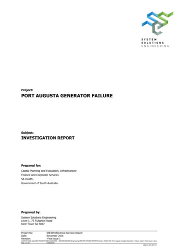
Under voltage (27) and over voltage(59)An under voltage element and a2-stage over voltage element areprovided. They are primarily used forbacking up the speed controlgovernor and the automatic voltageregulator. When severe over voltageoccurs, the high set of the overvoltage element can be set to providefast operation. Both elements are 3phase devices.Under frequency (81U) and overfrequency (81O)Two under frequency elements andone over frequency element areprovided. The underfrequencyelements are used to detectoverloading of the generator causedby various system disturbances oroperating conditions.The overfrequency element is used toback-up the speed control governor ifoverspeeding occurs.Voltage balance (60)The voltage balance function isprovided to detect VT fuse failure.It compares the secondary voltages oftwo sets of VTs (or from twoseparately fused circuits of a singleVT) and can be used to block possibleincorrect tripping of those protectionfunctions whose performance may beaffected by the apparent loss ofvoltage such as when a VT fuseruptures.ConfigurationIntegrating timer facilityTime integration is required for thepower function to allow forreciprocating load conditions wherethe measuring element may pick upbriefly and periodically. The samefeature is also provided for the fieldfailure function for pole-slippingconditions. Time integration allows thefunction to operate within its predetermined operating time.To implement timing integration, anadditional delayed drop-off timer isprovided. Once the protectionmeasurement element has picked up,the relay will operate after the set timedelay, provided that the time intervalwhen the element drops off is withinthe setting of the delayed drop-offtimer tDO.The protection scheme logic for agenerator set normally involves alarge number of protection functionscombined together to drive a fewcommon trip outputs. Some blockingand interlocking logic may also berequired. In order to accommodatedifferent generator applications, thescheme logic is flexible andreconfigureable.The LGPG111 scheme logic is in theform of logic arrays with anarchitecture commonly found inprogrammable logic array devices,having an internal AND-OR structureshown in Figure 7.The OR functions allow one or moreof the AND function outputs to controleach output relay, whilst the ANDfunctions provide blocking orinterlocking for two or more inputs, orjust a through connection for oneinput. There are 32 inputs to thescheme logic: 19 from the protectionfunctions, 8 optically-isolated inputsand a selection of inverted inputs toallow blocking logic to be created.The scheme logic controls a total of15 output relays and has 32selectable AND functions.Frequency trackingThe relay tracks the power systemfrequency and continuously adjusts itsinternal sampling clock to exactmultiples of the system frequency.This provides correct measurementsand operation of the protectionfunctions during start-up and run-downof the generator set when thegenerator unit is operated atabnormal frequency. The operatingfrequency range is from 25Hz to70Hz for the differential function andfrom 5Hz to 70Hz for the otherprotection functions.The input and output matrices allowthe desired connections to be created.Each intersection of the matrixrepresents a programmableinterconnection. By designing theappropriate interconnections and thenentering the information into the relay,Timer held facilityBoth the overcurrent function, the lowset element of the stator earth faultfunction and the neutral displacementfunction are provided with a timerheld facility. The purpose is to enablefaster clearance of recurrentintermittent faults, for example, selfsealing insulation faults. This facilityallows the relay timer to hold its valuewhen the current drops off, providedthat the drop-off period is less than thetRESET timer setting.This adjustable reset facility alsoenables closer co-ordination withelectromechanical induction discrelays.Scheme logicFrom protection elementsand status inputsOutput matrixANDANDANDInput matrixOR ORORTo output relaysFigure 7: Block diagram of the scheme logic5
through the scheme logic settings, therequired tripping logic can beconfigured.The presence of the optically-isolatedinputs to the scheme allows externaldevices such as rotor earth fault relay,temperature sensing devices andmechanical relays to be connected tothe scheme, so that the trippingfacilities, together with the alarm andremote communication facilities, canbe utilised.The optically-isolated inputs and relayoutputs used in a scheme may beallocated to any function required bythe application. The relay has afacility to label each of these byproviding an identifier. The identifiersare used during the configuration ofthe scheme logic, by the input andoutput status displays and by theevent, fault and disturbance recordingsystems.Alternative setting groupThe relay provides an alternativesetting group which consists of all theprotection and scheme logic settings.It can be used during start-up or rundown of generators or duringchanges in power systemconfiguration. This setting group canbe selected by either energising theappropriate optically-isolated inputs,or via the relay settings menu.Ancillary FunctionsMeasurementsThe magnitudes of all 17 analogueinputs to the relay are available fordisplay. Other derived quantities arealso available. This provides suchinformation as the three-phase,residual and earth currents, the phaseto phase voltages, differential andbias currents, negative phasesequence current, phase A active andreactive power plus the phase angleand power system frequency.All measurements can be displayed ineither primary or secondaryquantities, selectable by the user.Primary display quantities are basedon the settings for the CT and VTratios used by the relay.Event and fault recordsUp to 100 event records areavailable, all of them stored in nonvolatile memory. The latest record willautomatically overwrite the oldestone. Event records are generatedwhenever there is a protectionfunction operation, energisation of astatus input, operation of an outputrelay or any hardware failure.Fault records are also stored asevents. Out of the 100 event records,up to 50 fault records can beaccommodated. Fault records areinitiated when user selected relayoutputs operate. The record consists ofthe date and time of the fault, the stateof the optically-isolated inputs, relayoutputs and protection functions,together with the measurement valuesduring the fault.Disturbance recordsThe internal disturbance recorder canstore up to eight analogue channels,together with all the status input andrelay output information.The analogue channels are userselectable from the relay’s 17 inputs.The data in the analogue channelscan be stored as either raw data or asmagnitude and phase data. The rawdata is sampled at 12 samples perelectrical cycle, whereas themagnitude and phase data arecalculated once every 20ms. Thus theduration of a record varies with thedata type. For raw data, the duration6is 64 electrical cycles, but formagnitude and phase data, theduration is 7.68s. The latter set-upallows long duration events such aspole-slipping to be captured. In eithercase, each data entry is timestamped. This is particularly useful forthe raw data recording, since thesampling interval varies with thepower system frequency, due to thefrequency tracking.The disturbance recorder can betriggered from selected relay outputsand status inputs. A maximum of tworecords can be stored in volatilememory. A record remains in thebuffer area until it is uploaded to aPC, after which the buffer is released.If the two buffers are full, no furtherrecording can be made.Time synchronisationThe clock for event record timetagging has a resolution of 1ms.To provide time synchronisation withother equipment in the generatorstation, the clock can be synchronisedby external clock pulses (0.5, 1, 5,10, 15, 30 or 60 minute period) froman optically-isolated input.Print functionsSeveral print functions are provided toallow the relay to provide hard-copydocumentation, via the front panelparallel port. This consists of thesystem settings, protection settings,scheme logic settings, event recordsand fault records. The scheme logicprint-out is formatted so that it can becompared directly with the schemelogic diagram.Test featuresA number of features are provided toenable the relay to be thoroughlytested during commissioning, routinemaintenance and fault findingoperations: The measurement functions allowthe analogue input and itsassociated wiring to be checked. Display the on/off states of thestatus inputs and relay outputs. Testing the four indicating LEDs. Testing the relay outputs and theirassociated circuits by operatingthe relay output contacts.
Display the operation of eachprotection function as apercentage of the time-to-trip.This allows the pick-up, progressand operation of each protectionfunction to be checked. Testing the set-up of the schemelogic settings by manually enteringan input pattern to the scheme,and then examining its logicaloutput. This test can be performedat any time without interfering withthe relay’s operation.Power-on diagnostics and selfmonitoringPower-on diagnostic tests are carriedout by the relay when it is energised.These tests include checks on thetimer, microprocessor, memory andthe analogue input module.Continuous self-monitoring, in the formof watchdog circuitry, memory checksand analogue input module tests, isalso performed. In the event of afailure, the relay will either lock-out orattempt a recovery, depending on thetype of failure detected.Hardware DescriptionTwo relay output modules areprovided; each module contains 8miniature relays. All relays are selfreset. However, a software function isavailable which allows the user toselect outputs to be latched whenoperated.The relay is housed in a 4U (178mm)high case suitable for either rack orpanel mounting. Internally, it consistsof a number of plug-in modules whichare individually tested and calibrated.The modular hardware architecture isshown in Figure 8.The front panel consists of a 2 x 16character alphanumeric liquid crystaldisplay (lcd) and a 7 push-buttonkeypad. It provides local access to allof the relay’s features. There are also4 light emitting diodes for visualindication of the relay’s status, a nonisolated IEC870 serial port forconnection to a PC, and a parallelport for connection to a printer.The microcomputer module consists ofa powerful 16-bit microcomputerwhich controls all of the subsidiarymodules through a 64-way ribboncable called the I/O Bus.The processor performs all of themajor software functions such as inputsignal processing, protectionalgorithms, scheme logic, relay outputcontrols and handling of the operatorinterface.At the rear of the relay, apart from thenormal DC supply and plantconnections, there is an isolatedIEC870 port and a K-Bus port forpermanent connection to a remote PC.The analogue input module consists of12 CTs, 5 VTs and 6 optically-isolatedinputs. The CTs and VTs are used toisolate and condition the analogueinputs from the main transformersconnected to the generator.Their output signals are thenconverted into digital data for furtherprocessing.The remote communications moduleis responsible for handling thecommunications protocol and forcontrolling the three communicationports.In addition to the 6 optically-isolatedinputs on the analogue module, afurther 8 are provided by the statusinput module, making a total of 14optically-isolated inputs available tothe relay. 6 of these have pre-definedfunctions, such as clocksynchronisation, setting groupselection, etc., which leaves 8 inputsto be fed into the scheme logic.All of the optically-isolated inputsoperate from an auxiliary supplyVx(2), which is independent of themain auxiliary supply Vx(1).The ratings of Vx(1) and Vx(2) may bedifferent (See Technical Data).MicrocomputerI/O alogueinputsFrontpanelFigure 8: Hardware architecture7
User InterfaceFront panel user interfaceThe features of the relay can beaccessed through a user-friendly menusystem. The menu is arranged so thatrelated items (menu cells) are groupedinto individual sections, each of whichis identified by a title. The usernavigates around the menu by usingthe arrow keys, first to select aparticular section title and then toselect an item within it. The frontpanel liquid crystal display is limitedto displaying one menu cell at a time.Software is available with each KITZto provide access to the relays, toread and change settings. Additionalsoftware entitled Protection AccessSoftware and Toolkit is available togive access to the event recorder,together with other additionalfunctions.Each relay is directly addressable viathe bus to allow communication withthe PC. It should be noted thatprotection tripping and blockingsignals are not routed via the K-Bus.Separate conventional wiring is usedfor these functions.Remote access user interfaceThe menu can be accessed via theremote communications facility.This allows all of the menu cells in asection to be displayed on the screenof a PC. Changes to the menu cellcan be made from the PC keyboard.Relay interconnectionThree communication ports areavailable: the front panel, nonisolated IEC870 port; the rear,isolated IEC870 port; and the K-Busport. The IEC870 ports use RS232signal levels and allow point-to-pointconnection. It is applicable whennetworking is not required or duringcommissioning.Alternatively, the relays can beconnected via a shielded, twisted paircalled K-Bus. Up to 32 relays may beconnected in parallel to the bus.K-Bus can be connected through aprotocol converter, type KITZ, eitherdirectly or via a modem, to the RS232port of a PC. K-Bus is RS485 basedand runs at 64kbits/s. The K-Busconnection is shown in Figure 9.SK1Figure 9: K-Bus terminals connection arrangement8
27 and 81Uinhibit51V timerinhibit51N timerinhibitB25A7B26 VabI 7G1Ia—biasG3A18A19A22A9Ia—sensitiveSetting groupselect(Part)IntegratedGeneratorProtection A15IcA16A5G15G14Logic input 10G19G18IeA6B19G20B20G23VeLogic input 12G16G17Logic input 13Relay 5DC supply Vx(1) –G21G22RearIEC870port(isolated)G25G26G289Figure 10: External connection diagram Type LGPG111 (typical scheme)B8B9F8Relay 9F2F7Relay 10Relay ,Ic—bias,87G Generator differentialIa, Ib, eneratorProtection RelayRelay 11F10F12F15Relay 12F16F19F21F23Relay 14F22D16D19F24D20D23F27F25Relay 15F26Ve59N Neutral displacement67N SDEF (polarising)275981U81032R32L4060Vab—comp 60Vbc—compF28D24D2751N Stator earth fault67N SDEF (polarising)Vab, VbcF20D14D15IeI—residual 67N SDEF (operating)Relay 13F18D10D13OvercurrentNegative phase sequenceField failure (Ia)Under frequency (Ia)Over frequency (Ia)Ia—sensitive 32R Reverse power32L Low forward powerF13Under voltageOver voltageUnder frequencyOver frequencyReverse power (Vab)Low forward power (Vab)Field failure (Vab)Voltage balanceVoltage balance(Comparison aseearthRelay 6G24G27F4F17Logic input 11Relay 4B6B7D6D9G12IaF6Logic input 7Logic input 9Relay 3B4B5F14G9G11F1D2D5Relay 2Relay 8F3Logic input 6Logic input 8Note: CT and VT assignmentsF5B2B3B12D1Relay 1G4G7Phase rotationBRelay inoperativealarmG6LGPG111Ic—biasCB24 Vbc— compIc—diffA20A21AB21B22 Vab — compIb—diffIb—biasSetting groupselectA B CB28 VbcB1Notes:1. (a)(b)CT shorting links makebefore terminals disconnect.Short terminals break before (a).2. CT connections are typical only.3. SCN Screen connection for K-Bus.2 TX3 RX17signal ground1protective groundK-Busport2SCN4. The IEC870 port at the front panel is non-isolatedand has different connection arrangements.5. Frequency tracking on Vab, Vbc and Ia only.6. Logic inputs are rated at Vx(2).7. SDEF Sensitive directional earth fault.
10Input 13Input 12Input 11Input 10Input 9–Input 9Input 8Relay 1Relay 2Relay 3Relay 4Relay 5Relay 6Relay 7Output InhibitedENENInput MatrixRelay 8Relay 9Relay 10Relay 11Relay 12Relay 13Relay 14Relay 152ms pick-up, 8ms drop-off–Input 82ms pick-up, 2ms drop-offRelays 4, 5, 6, 7,12, 13, 14, 15Input 7Relays 3, 11–Input 78ms pick-up, 8ms drop-offInput 6Relays 1, 2, 8, 9, 10–Input 6Note: Speed of the relay outputs are:60 VB Comp–60 VB–Prot (Blocking)60 VB–Prot40 Field FailureFigure 11: Type LGPG111 scheme logic67N Sensitive Dir EF59N–2 Neutral Disp59N–1 Neutral Disp51N Stator EF51N Stator EF46 NPS Trip46 NPS Alarm59 Over Voltage27 Under Voltage81U–2 Under Freq81U–1 Under Freq81O Over Freq32L Low Forward Power32R Reverse Power51V Over Current87G Generator Ouput Matrix
Technical DataRatingsInputsAC Current In1A or 5AAC Voltage Vn100V to 120VAuxiliary voltage Vx(1)(Relay power supply)Auxiliary voltage Vx(2)(Optically isolated status input supply)Nominal dc (V)24/2730/3448/54110/125220/250Operative range (V)19.2 – 32.424 – 40.838.4 – 64.888 – 150176 – ––––32.440.864.8150300Note: Vx(2) may be different fromVx(1)Frequency Fn50/60HzBurdensAC CurrentGenerator differential 0.05VA per input at In (for 1A relay) 0.20VA per input at In (for 5A relay)Voltage dependent overcurrent,field failure and negativephase sequenceReverse and low forward powerStator earth fault andsensitive directional earth fault 0.05VA per input at In (for 1A relay) 0.22VA per input at In (for 5A relay) 0.15VA at In (for 1A relay) 0.30VA at In (for 5A relay) 0.12VA per input at In (for 1A relay) 0.25VA per input at In (for 5A relay)AC Voltage 0.005VA per input at VnDC auxiliary voltage (Vx(1))DC auxiliary voltage (Vx(2))15W quiescent, max. 34W operating.Less than 0.32W on average per inputTransformer ratiosCT ratios1:1 to 9999:1 in 0.01 stepsVT ratios1:1 to 9999:1 in 0.01 stepsCT requirementsGenerator differentialBiased differentialsettings at Is1 0.05In,k1 0%, Is2 1.2In,k2 150%Vk 50In (Rct 2RL Rr)where maximumthrough fault current 10 x In andmaximum X/R 120Vk 30In (Rct 2RL Rr)where maximumthrough fault current 10 x In andmaximum X/R 60Note: Minimum knee point voltage 34V11
Earth fault protection functionsSensitive directionalearth fault, using threeresidually connectedline CTsVk 6In (Rct 2RL Rr)where maximumX/R 5 andmaximum earth faultcurrent 1 x InSensitive directionalearth fault, using corebalance CTVk 6NIn (Rct 2RL Rr)where maximumX/R 5 andmaximum earth faultcurrent 2 x InStator earth faultVk 6NIn (Rct 2RL Rr)Ancillary protection functionsVoltage dependentovercurrent, field failureand negative phasesequenceVk 20In (Rct 2RL Rr)where Vk Minimum current transformer knee-point voltage for stabilityIn Relay rated current (1A or 5A)Rct Resistance of current transformer secondary winding (Ω)RL Resistance of a single lead from relay to current transformer (Ω)Rr Resistance of any other protection functions sharing the currenttransformer (Ω)N Maximum earth fault currentCore balanced CT or earth CT rated primary currentNote: N should not be greater than 2. The core balance CT or earth CT ratiomust be selected accordingly.Power functionFor settings 3% PnUse correctly loaded class 5P protection CTFor settings 3% PnUse metering class CT. See table below.Metering CT class recommended for power setting less than 3%PnReverse/low forward Power Setting(%Pn)0.20.4Metering CT 3.0121.0
Thermal withstandContinuous withstand CT input4 x InVT input400VCT input100A for 1s (In 1A)Short time withstand400A for 1s (In 5A)Setting rangesGenerator differentialBasic differential current setting Is10.05In to 0.1In in 0.01In stepsThreshold for increase bias Is21In to 5In in 0.1In stepsBias K1 (Ibias Is2)0% to 20% in 5% stepsBias K2 (Ibias Is2)10% to 150% in 10% stepsStator earth faultLow set element:CharacteristicStandard inverse/Definite timeCurrent setting Ie 0.005In to 0.5In in 0.005In stepsTime multiplier setting TMS0.05 to 1.2 in 0.05 stepsIDMT Operating characteristict Definite time setting t 0.1s to 10s in 0.1s stepsReset timer setting tRESET0s to 60s in 1s steps0.14x TMS(I/Ie )0.02–1High set element:Current setting Ie 0.005In to 2In in 0.005In stepsTime setting t 0s to 5s in 0.1s stepsNeutral displacementVoltage setting Ve 1V to 25V in 1V stepsTimer 1 setting t10.5s to 5s in 0.5s stepsTimer 2 setting t21s to 10s in 1s stepsTimer 2’s reset timer t2RESET0s to 60s in 1s stepsSensitive directional earth faultOperating current Ires 0.005In to 0.02In in 0.005In stepsPolarising voltage Vp 1V to 10V in 1V stepsPolarising current Ip 0.005In to 0.02In in 0.005In stepsRelay characteristic angle RCA–95 to 95 in 1 stepsVoltage dependent overcurrentFunctionsVoltage tandard Inverse/Definite TimeCurrent setting I 0.5In to 2.4In in 0.05In stepsTime multiplier TMS0.05 to 1.2 in 0.05 stepsIDMT Operating characteristict Definite time setting t0s to 10s in 0.1s stepsReset timer setting tRESET0s to 60s in 1s steps0.14(I/I )0.02–1x TMS13
Voltage settings:Vs (for voltage controlled)20V to 120V in 1V stepsVs1 (for voltage restrained)80V to 120V in 1V stepsVs2 (for voltage restrainted)
Protection Relay Figure 1: Relay Type LGPG111 Introduction The LGPG111 is a multi-function relay which integrates a number of common . 59N 51V 32R 32L 40 46 27 59 81U 81O 60 87G. 4 Reverse power (32R) and low forward power (32L) Reverse power protection is used to detect loss of the prime mover.