Transcription
Installation NotesSP PRO Grid Fail - Generator Backup KitInstallation NoteIntroductionThis installation note details the addition of the Grid fail-Generator backup kit to the SP PROinverter. The kit is only suitable for the small range (SPMC) of SP PRO AU or GO series (SeriesII) in a single phase or a three phase Advanced Multiphase Solar Hybrid installation.NOTE: Three kits are required for a three phase Advanced Multiphase Solar Hybrid installation.The Grid fail - Generator Backup ONLY operates with Auto Start generators and CANNNOT BEUSED with manual start generators. A three phase generator must be used in a three phaseinstallation.When the Grid fail-Generator backup kit is installed into the SP PRO, the system allows for theconnection of an auto start backup generator that is automatically started and stopped by theSP PRO as required during a grid outage.SP PRO ModelsSPMCSPMCSPMCSPMCSPMC240-AU, 004723241-AU, 004724481-AU, 004725482-AU, 0047261201-AU, 004722Grid fail – Generator backupkit, single phase.Grid fail – Generator backupkits, three phase.1 off SPMCA-GFGB-2448, 0052683 off SPMCA-GFGB-2448, 005268No Kit AvailableNo Kit AvailablePreparation When installing a single phase system, make sure one Grid Fail Generator Backup kit (005268) ison site.When installing a three phase Advanced Multiphase system, make sure three Grid Fail GeneratorBackup kits (3 x 005268) are on site.- If installing a three phase system, make sure the AMP Three Phase kit is on site(Order code 005304)This document needs to be read in conjunction with the SP PRO Instruction Manual and SP LINKinstruction manual (both found in SP LINK Help menu)Additional informationSelectronic web site – http://www.selectronic.com.au or contact the Selectronic Sales TeamThis document applies for SP PRO Series II Rev 21 and aboveIN0020 Revision 05 004799 – 1 of 8POWERPERFORMANCEPASSION
Installation NotesOperationThe Grid Fail - Generator Backup (GFGB) functions as follows:1. When the grid is available and in tolerance the grid is connected via the GFGB contactorto the SP PRO and the SP PRO synchronises to the grid as per normal Solar HybridOperation.2. When the grid fails, or is out of voltage or frequency tolerance (as per the settings in theSP PRO), the SP PRO will disconnect from the grid via the SP PRO AC source contactor.At this stage, the GFGB contactor is keeping the SP PRO attached to the grid supply, andif the grid is restored then the SP PRO will again synchronise to the grid.3. The SP PRO will continue to power the loads from the battery bank and any connectedrenewable energy until the grid is restored.4. If the grid is not restored before a “Generator start” condition, the SP PRO willautomatically start the generator and switch over the GFGB contactor to connect theSP PRO AC source input to the generator supply. The SP PRO will then synchronise tothe generator to charge the batteries and power the loads.5. When the “Generator Stop” condition is satisfied, the SP PRO stops the generator andcontinues to run from the battery and any connected renewable energy. This cycle willcontinue until the grid is restored.6. When the grid is restored and stable for 60 seconds, the SP PRO will stop the generator(if it is running and has been running longer than the “Minimum Runtime” inConfiguration Settings AC Source Generator Controller Settings), disconnect its ACsource contactor then switch over the GFGB contactor to return the SP PRO to the grid.The SP PRO will then synchronise to the grid.Note: The GFGB contactor is a break before make changeover contactor. This ensures that thegenerator supply and grid supply cannot be cross connected.IN0020 Revision 05 004799 – 2 of 8POWERPERFORMANCEPASSION
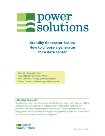
Installation NotesWiring OverviewThe following is an overview of the internal and external connections which form part of theGrid Fail – Generator Backup Expansion housing.Grid Fail – Generator Backup in a Single phase systemNote: Diagram is applicable for 24V and 48V SP PRO.Grid Fail – Generator Backup in an Advanced Multiphase systemIN0020 Revision 05 004799 – 3 of 8POWERPERFORMANCEPASSION
Installation NotesSP PRO InstallationThe SP PRO must be installed as per the installation instructions in the user manual.All wiring is carried out in the SP PRO with the exception of the grid L input and the generator Linput wiring. These are wired to the Grid fail-Generator backup kit once it is installed.Note: For Advanced Multiphase systems, one Grid fail-Generator backup module is installed ineach SP PRO.When connecting the AC wiring to the SP PRO, please leave enough space for the Grid failGenerator backup kit to be installed in the wiring cavity of the SP PRO.Please note the following:1. Backup loads connect into the AC Load L and N terminals in the SP PRO.2. Only the L wire from the Grid fail-Generator backup connects into the AC Source Lterminal within the SP PRO.3. The Grid L connects to the GRID L terminal on the Grid fail-Generator backup kit. TheGrid N connects to the AC source N on the SP PRO.4. The Generator L connects to the GEN L terminal on the Grid fail-Generator backup kit.The Generator N connects to the AC source N on the SP PRO.Once the SP PRO has been installed and wired, follow the steps below to install the Grid fail –Generator backup kit.IN0020 Revision 05 004799 – 4 of 8POWERPERFORMANCEPASSION
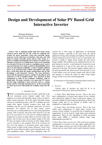
Installation NotesInstalling the Grid fail-Generator backup kit into the SP PROReferring to the diagram above (page 4), follow the steps below to install the kit.1. Fit 2 x 5mm mounting screws to the base of the SP PRO inverter at position A. Leavescrews loose.2. Fit Grid fail-Generator backup kit to screws as shown. Tighten screws.3. Wire the connections from the Grid fail-Generator backup kit to the SP PRO as shown.NOTE the polarity of the B and B- connections4. Wire the Generator L and Grid L to the GEN L and GRID L terminals respectively on theGrid fail-Generator backup kit.5. Double check all terminals are tight and clamping the wire only and not the insulation.Generator Control WiringThe Generator Run control wiring is wired into the expansion card as shown. This configurationis for a controller that require two wires to be closed to start and run and then opened to stopthe generator.In a three phase Advanced Multiphase system the Generator Control Wiring is ONLY connectedto the SP PRO on the L1 phase.Note: Refer to Tech Note TN0025 for other control options.SP PRO Configuration – Additional Configuration SettingsThe Site Configuration Wizard is used to configuration the SP PRO with the Grid Fail –Generator Backup. Step though the wizard to setup the system to suite the appropriateapplication.Note: For more information when stuck through the “Site Configuration Wizard”, right click onthe page and a help guide will appear to help setup the system.The settings detailed in Appendix I (pages 7 to 8) will be set when the Site ConfigurationWizard is used to configure the SP PRO. Only the settings required to enable Grid Fail –Generator Backup are shown. The remainder of systems settings will be set by the SiteConfiguration Wizard.IN0020 Revision 05 004799 – 5 of 8POWERPERFORMANCEPASSION
Installation NotesSP PRO CONFIGURATION – AUTOMATIC GENERATOR CONTROLThe generator will run upon loss of grid supply on the default settings based on low batteryvoltage or SoC if enabled. If you wish to enhance this operation, consult SP PRO User manual– Generator Automatic Start for full details.Reference InformationRL1 - VOLTAGE MONITORThe internal voltage monitor (RL1) is factory set and should not be adjusted. The factorysetting is detailed below:: 15 %:-8%:3s: DIP-switches – under cover –123456––––––ON (DEL-REC)OFF (N.E.)ON (6 s)OFF (INHIBIT)ON (230 VAC)OFF (230 VAC)WARNING: Do not open the DIP-switches cover if the Power Supply is ON.IN0020 Revision 05 004799 – 6 of 8POWERPERFORMANCEPASSION
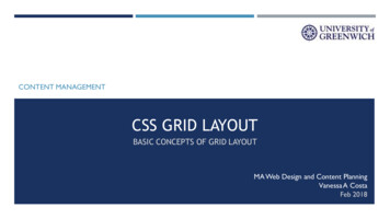
Installation NotesAppendix I: SP LINK Configuration CheckAC SOURCE – AC INPUTCheck the Alternative Source is set to accommodate the different power limit andvoltage/frequency range that the SP PRO will accept when the backup generator is running.The Primary Source settings are shown by way of comparison between grid and backupgenerator.Alternate AC Source Power – maximum power SP PRO will draw from backup generatorMin, Max AC Voltage – allowable voltage range from generatorMin, Max AC Frequency – allowable frequency range from generatorNote: Default Values shown - Adjust values to suit the backup generator. External CT andExtern. Contactor/CT settings are not used in this configuration.AC SOURCE – GENERATOR CONTROLLER SETTINGSGenerator Controller: EnabledNote: Remaining settings canbe adjusted based on specificbackup generatorrequirements. See SP PROUser Manual – GeneratorController Settings for furtherdetails.IN0020 Revision 05 004799 – 7 of 8POWERPERFORMANCEPASSION
Installation NotesINPUTS / OUTPUTSMake sure the SP PRO is configured to control the correct inputs and outputs to monitor andswitch between the grid and backup generator.Digital Inputs –Normal/Alternate AC Input Power Selector: Follow Backup SelectInhibit Export Input: Follow Backup SelectNote: Low Batt Shut Down Override Input setting is not used in thisconfiguration.Grid Fail Generator Backup –Grid Fail Backup: EnabledGrid Available Input: Digital Control Input 4Backup Select Output: Relay Output 3Generator Outputs –Generator Run Output – Relay Output 1The actual generator output type used will depend on what signal isrequired by the backup generator to start and stop. Refer to generatordocumentation for details.Note: Default settings shown. Start Output is not used in thisconfiguration.IN0020 Revision 05 004799 – 8 of 8POWERPERFORMANCEPASSION
When the Grid fail-Generator backup kit is installed into the SP PRO, the system allows for the connection of an auto start backup generator that is automatically started and stopped by the SP PRO as required during a grid outage. SP PRO Models Grid fail - Generator backup kit, single phase. Grid fail - Generator backup kits, three phase.