Transcription
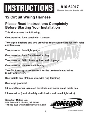
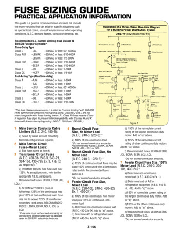
Fuse Sizing GuidePractical Application InformationThis guide is a general recommendation and does not includethe many variables that can exist for specific situations suchas special local codes, unusual temperature or other operatingconditions, N.E.C. demand factors, conductor derating, etc.Recommended U.L. Current Limiting Fuse Classes &EDISON Fusegear Symbols:*Time-Delay TypeClass L–LCL–600VAC or less: 601-6000AClass RK1–LENRK –250VAC or less: 6/10-600A–LESRK –600VAC or less: 1/2-600AClass RK5–ECNR–250VAC or less: 1/10-600A–ECSR–600VAC or less: 1/10-600AClass J–JDL–600VAC or less: 1-600AClass CC–HCTR–600VAC or less: 1/4-10AFast-Acting Type (Non/time-delay)Class T–TJN–300VAC or less: 1-800A–TJS–600VAC or less: 1-800AClass L–LCU–600VAC or less: 601-6000AClass RK1–NCLR–250VAC or less: 1-600A–SCLR–600VAC or less: 1-600AClass J–JFL–600VAC or less: 1-600AClass CC–HCLR–600VAC or less: 1/10-30A*The fuse classes shown are U.L. Listed as “current limiting” with 200,000RMS symmetrical amperes interrupting rating. Classes J and L are notinterchangeable with fuses having lower l.R. Class R fuses require ClassR rejection fuse clips to prevent interchangeability with Classes H and Kfuses with lower interrupting rating. (N.E.C. 110-9 and 240-60b.)1 Main Service Conductor CableLimiters (N.E.C. 240, 450-6):a) Select by cable size and mountingterminal configurations required.2 Main Service CircuitFuses–Mixed Loads:a) Size fuses same as item 6.3 Transformer Circuit Fuses(N.E.C. 450-3b, 240-3, 240-21,384-16d, 430-72b Ex. 3, 4 & (c)as required):*a) PRIMARY FUSES: Size fuses not over125%. As exceptions exist, refer to theappropriate N.E.C. paragraphs.Recommended fuses: LESRK, ECSR, JDL,LCL .*b) SECONDARY FUSES (Sum offollowing): 125% of the continuous loadplus 100% of non-continuous load. Fusesize not to exceed 125% of transformersecondary rated amps. RECOMMENDEDFUSES: LENRK, ECNR, NCLR, JDL orLCU.*Fuse size must not exceed ampacity ofconductors. Where selectivity is desired,refer to EDISON selectivity methods.4 Branch Circuit FuseSize, No Motor Load(N.E.C. 240-3, 220-3):*a) 100% of non-continuous load.*Do not exceed conductor ampacity.Recommended fuses: LENRK, ECNR,NCLR, JDL, LCU, or LCL.5 Branch Circuit Fuse Size, NoMotor Load(N.E.C. 240-3, -220-3):*a) 125% of continuous load. Fuse may besized 100% when used with a continuousrated switch. Recom-mended fusessame as 4.*Do not exceed conductor ampacity.6 Feeder Circuit Fuse Size,Mixed Load(N.E.C. 220-10b, 240-3, 430-22aEx. 1, 430-24):*a) 100% of non-continuous, non-motorload plus 125% of continuous, non-motor loadb) Determine non-continuous motor load(N.E.C. 430-22a EX. Add to “a)” above.c) Determine A/C or refrigeration load.(N.E.C. 440-3b). Add to “a)” above.Z-106Figure 1d) 150% of the nameplate currentrating of the largest continuous-dutymotor. Add to “a)” above.e) 125% of the nameplate currentrating of other continuous duty motors.Add to “a)” above.f) Recommended fuses: LENRK/LESRK,JDL, ECNR/ ECSR, LCU, LCL.*Do not exceed conductor ampacity.7 Feeder Circuit Fuse Size, 100%Motor Load (N.E.C. 240-3, 220-10b, 430-24):*a) Determine non-continuousmotorload (N.E.C. 430-22a Ex. 1).b) Determine load of A/C orrefrigeration equipment (N.E.C. 440-3,-5, -12). Add to “a)” above.c)150% of nameplate current rating ofthe largest continuous duty motor. Addto “a)” above.d)125% of the other continuous-dutymotors. Add to “a)” above.e)Recommended fuses: LENRK/LESRK,JDL, ECNR/ ECSR or LCL.*Do not exceed conductor ampacity.
Practical Application InformationLevels of Government regulations and ordinances, from Federal tolocal, usually base acceptable safe performance and application offuses and circuit breakers on the National Electrical Code. The NECcommonly refers proven safe performance to the Standards ofSafety of Underwriters Laboratories, Inc. The NEC is sponsored bythe National Fire Protection Association.8 Branch Circuit Fuse Size, Individual Motor Load,With Fuse Overload Protection (No StarterOverload Relays): (N.E.C. 430-32, 430-36):Therefore, fuses manufactured to meet the same standards ofU.L. testing and “Listing” for specific types are physically andelectrically interchangeable, based on the standards, regardlessof brand.a) Motors with 1.15 Service Factor or temperature rise notover 40 Degrees C., size fuses at not more than 125% of themotor nameplate current rating.b) Best protection is obtained by measuring motor runningcurrent and sizing fuses at 125% of measuredcurrent fornormal motor operation. Referenceto “Average Time/CurrentCurves” is recommended.Fuses can be designed and manufactured to higher standards thanthe minimum standards required to pass U.L. testing tobe “Listed”.For all of the reasons above, Edison Fuses Inc. manufacturesfuses not only to meet industry standards, but also to reach thehighest quality standards found in the industry.d) Recommended Fuses: LENRK/LESRK, JDL, or ECNR/ECSR .9 Branch Circuit Fuse Size, Individual Motor Load,With Starter Overload Relays(N.E.C. 430-32, 430-52):National Electrical CodeThe National Electrical Code (N.E.C.) is sponsored by the NationalFire Protection Association. This Code is adopted as the MINIMUMstandard for public safety by the federal government, states,counties, cities and many private organizations. Enforcement isusually the responsibility of Professional Electrical Inspectorsprovided with enforcement authority.a) For “back-up” N.E.C. overload, ground fault and shortcircuit protection size the fuses the same as (8 a, b) above, orthe next standard size larger.b) The fuse sizes in a) above may be increased as allowed byNEC references. Generally, dual element fuses should notexceed 175% of motor nameplate F.L.A. and non-U.L. definedtime-delay fuses not more than 300%.Fuse Ratingsc) Recommended fuses: LENRK/LESRK, JDL, ECNR/ECSR or LCL.10 Fuse Sizing for Individual Large Motors WithF.L.A. Above 480 Amps or Otherwise RequireClass L Fuses - (N.E.C. 430-52):Application Tips1. Size fuses as closely as practical to the ampacity of theprotected circuit components without the probability ofunnecessary fuse opening from harmless, transient currentsurges. This usually requires a choice between time-delay andnon-time-delay fuses.Fuses with an A-C voltage rating may be applied at systemvoltages below the fuse voltage rating, but not at voltages abovethe fuse voltage rating. The other A-C fuse ratings remain thesame at applied voltages below the fuse voltage rating.A-C rated fuses should not be applied in D-C voltage circuitsunless D-C application ratings are provided by the fusemanufacturer. Except for some special purpose fuses, D-C ratingsare not usually shown on fuse labels.2. Use Class R fuse clips with Class R fuses to prevent installationof fuses with less interrupting rating or current limitation. Class Hfuse reducers cannot be used with Class R fuse clips.3. When a conductor is oversized to prevent excess voltage drop,size the fuses for the ampacity of protected circuit componentsinstead of oversizing fuses for the larger conductor.EDISON Time/Current Curves, Peak Let-Through Curves are basedon 60 Hertz A-C data.The operating frequency (Hertz) will affect fuse characteristics invarious ways.SafetyIndustry PUBLIC SAFETY standards that apply to overcurrentprotection devices (OPD), fuses and circuit breakers, are intendedto apply to both types of devices. The use of these devices servespublic safety which includes all aspects of fuse or circuit breakerperformance and dependability.Time/Current Curves will not shift and fuse ratings will not changefrom 1-100 Hertz in normal applications. If ferrous hardware isused to mount the fuses, eddy current heating could alter theratings.Above 100 Hertz, “skin effect” could alter the fuses’ ratingcharacteristics. This effect must be analyzed on an individualapplication basis.Any industry requirements that apply to fuses apply equally tocircuit breakers. Industry standards do not intend any deliberatecompromises for public safety.Z-107
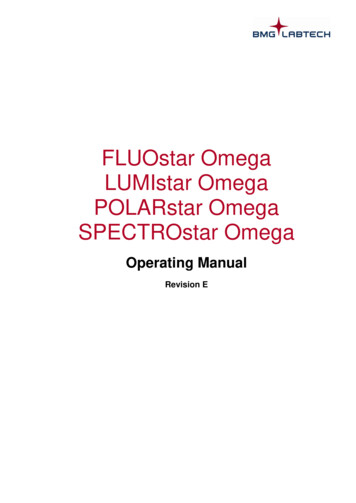
Practical Application InformationFuse ratings, Cont.Other characteristics shown on fuse labels such as “interruptingrating”, “current limiting”, “time-delay”, “fast-acting” andUnderwriters Laboratories, Inc. (U.L.) Class are describedelsewhere.Correction Factors for Edison Fast-Acting and NonDelayFuses(1)Factors for Edison Fast-Acting and NonCorrectionDelay Fuses(1)Ambient CelsiusMaximum Load CurrentTemperatures(%of Rating)Ambient CelsiusMaximumLoad Current-20to -4093%Temperatures(% of Rating)-1990%-20toto-1-4093%zeroto -12486%-19 to90%25to 60%(1)Fuses installed81 to 100in an enclosure with a base loading45% of 80% as required by theNationalElectricalinCode.Contact EdisonFusesloadingInc. forofother(1)Fuses installedan enclosurewith a base80%conditions.as required by theFuse labels show “certification” or “listing” logo’s when applicable.Such logo’s may be: “U.L.” (U.L. “Listed”) “CSA” (Canadian Standards Association “certified”) (U.L. Recognized)Such logos mean that the fuse meets the performance standardsof these safety organizations.National Electrical Code. Contact Edison Fuses Inc. for other conditions.Interrupting Rating (I.R.)Some EDISON fuses, such as rectifier protection fuses, specialpurpose fuses, etc., do not show safety organization logosbecause test standards do not exist, or logo’s are awaiting testingfor newly established standards. In these cases, any necessaryadditional information may be obtained from the manufacturer.N.E.C. 110-9 requires that the interrupting rating of fuses andbreakers not be less than the maximum available short circuitcurrent at their point-of-application as indicated by Figure 2.Circuits where fuses and breakers are installed may be capable ofthousands of amperes of short circuit current flow during a shortcircuit condition. When fuses or breakers are installed where thevalue of short circuit current flow may exceed the interrupting ratingof the devices, a very serious safety hazard may exist. A flow ofshort circuit current in excess of the device interrupting rating maycause only a mild device rupture during device opening or a violentexplosion depending on the value of excess short circuitcurrent flow.Ambient Fuse De-Rating.Fuses designed to U.S.A. standards are tested for proper ampereratings at 25 degrees Centigrade. Since fuses operate by heatmelting fuse elements, the ampere ratings can change for higheror lower ambient temperature (temperature of air around anenclosure in which fuses are installed). The following informationis provided to choose fuses with different ampere ratings forunusually highFactorsor low ambienttemperatures.Correctionfor EdisonDual-Element ECNR/ECSRand LENRK/LESRKFuses(1) Dual-Element(See next column)CorrectionFactors for EdisonECNR/AmbientCarrying(1)Capacity% ofECSRand LENRK/LESRK Fuses(See next column)TemperaturesofFuse inCapacityAmbientCarrying C F%RatinTemperaturesofofFusein-60-76120 C F% of 5100212608017675*No correctionneeded100212 with this range. 60Opening% 100859570855070355035*No correction needed with this range.Figure 2OvercurrentThe term “overcurrent” refers to abnormal current flow higher thanthe normal value of current flow in an electrical circuit. Uncorrected“overcurrent” can cause serious safety hazards and costly damage toelectrical equipment and property.Z-108
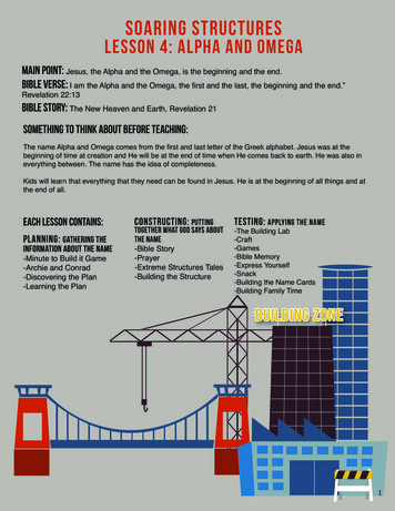
Practical Application InformationI TOTAL OHMS4800.01 10.0 0.01Fuses and most circuit breakers are installed in electrical circuitsto open and stop the flow of “overcurrent”.I 47.9 amperesFuses and typical circuit breakers respond and open for both lowand high values of overcurrent flow. “Limiters” and “magneticonly” circuit breakers respond only to high values ofovercurrent flow.Overload Example:overcurrent, Cont.The Figure 3 value of “overload” current may be up to about 10times the normal current value of 47.9 amperes.Imagine working at a drill press. Suddenly, the drill becomeswedged in a steel block.There are three basic types of current flow in an electrical circuit:1. Normal intended current flow to operate electrical equipment.2. Abnormal overcurrent flow with a value of up to 10 timesnormal current flow. This is known as an “overload”.3. Abnormal overcurrent flow with a value more than 10 times thenormal current flow is known as “short-circuit” or “fault”current flow.Unless otherwise noted, current (amperes) and voltage (volts) arealternating current/voltage RMS values as read on an ammeter orvoltmeter. The alternating frequency is 60 HZ (cycles per second).Impedance is a combination of resistance and inductive reactanceand is expressed in units of ohms.Instead of continuing to draw normal motor load current, thelocked drill motor shaft causes the motor to draw “Locked RotorCurrent” which is about six times the normal load current.Overcurrent Protection Device Symbols.Damage may be serious unless the overcurrent protection deviceopens in time to prevent damage.EDISON Multi-Purpose, dual element fuses, properly sized,provide excellent protection for similar applications.Figure 4Ohm’s Law is used to find the value of normal current flow in thesimple circuit illustration. (See Figure 3)I VOLTSFigure 4 is identical to Figure 3 except a short-circuit fault has beenshown that by-passes the impedance of the load of 10 ohms. Theonly impedance remaining to oppose the flow of current is 0.02ohms which is the total impedance of the conductors. Short-circuitcurrent now flows around the load as shown by the arrow in theheavy line.The value of short-circuit current flow for this simple illustration isdetermined by using Ohm’s Law:ISC VOLTSTOTAL OHMSISC 480 24,000 amperes(0.02)There are many specific ways that short-circuits (faults) may occur.Some of the more common are accidents, carelessness in themisuse of “fish tape”, tools, etc., crossed phases, contamination,rodents, damaged insulation and unfused small conductors.Figure 3Z-109
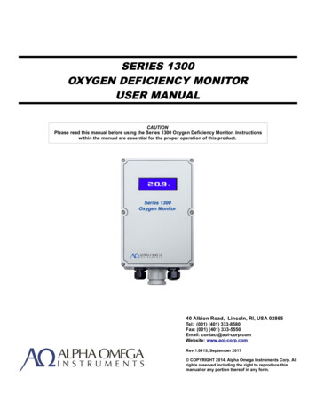
Practical Application InformationOvercurrent Protection Devices.Fusesand Circuit BreakersBreaker “Off”Fuses contain an element that acts like a conductor for the normalcurrent flow. The element’s ability to sense abnormal current isthe basis for the amp rating of the fuse. When an overcurrentdevelops that exceeds the fuse rating, heat builds up inside thefuse and melts or “opens” the element. Once the element ismelted and the arc extinguished, current flow stops.When the overload or fault condition that caused the fuse to openis corrected, a proper replacement fuse restores the originaldependable protection.Fuse showingelement during normaloperationSummaryElement intactIt is obviously necessary to rate fuses and circuit breakers accordingto their ability to safely interrupt a given MAXlMUM value of shortcircuit current flow.Fuse showing elementmelted by anovercurrentStandard U.L. Fuse Interrupting Ratings*Class H10,000Class K50,000, 100,000 or 200,000Classes J, L, R, T, and CC200,000Class G100,000Element meltedStandard U.L. Circuit BreakerInterrupting ,00035,000*Contact manufacturer for availability of ratings.Circuit Breakers contain a resettable latch which acts like an“ON-OFF” switch for the normal current flow. When abnormalcurrent flows through the circuit breaker, the latch trips, and theindicator on the outside of the circuit breaker moves into the“OFF” position. Once the overcurrent problem has been corrected,the indicator lever can be reset into the “ON” position, whichsimultaneously resets the latch inside the circuit 000200,000Figure55FigureA specific fuse or breaker may be submitted for testing at one ofthe standard levels shown in Figure 5. The successful producttesting results in “listing” of the product as having an “interruptingrating” (I.R.) at the level of test current. In other words, when afuse or circuit breaker will safely interrupt developed energy ata specific value of short-circuit current, say 200,000 Irms, theproduct manufacturer may place a UL logo and words similar to“Interrupting Rating 200,000 Amps A-C” on the product label. Theproduct will interrupt any value of fault current up to 200,000 IrmsMAXIMUM.Breaker “On”When fuses and circuit breakers are properly applied within theirinterrupting rating, as required by N.E.C. 110-9, device openingduring short-circuit current flow generates high levels of energyinside the devices.Z-110
Practical Application InformationEDISON current limiting fuses are designed to retain their highinterrupting rating in normal use until caused to open and are thenreplaced with a new fuse.Magnitude of AvailableShort-Circuit CurrentFigure 6 shows maximum values of available short-circuit currentat the secondary terminals of some typical sizes of building mainservice transformers. Note, the increased values of amperes whenthree single-phase transformers are connected for three-phaseoperation. For this situation, the percent internal impedance (%Z)of the three transformers must be matched. The three-phase %Z isthe same as for one of the single transformers.Transformer System VoltageKVASingle-PhaseSize120/240V37-1/218,000 A.5022,000 A.10044,000 A.25082,000 A.33398,000 A.500184,000 A.750–750*–1000–1000*–*Three-single-phase V18,000 A.40,000 A.8,000 A.18,000 A.82,000 A.42,000 A.122,000 A.56,000 A.132,000 A.35,000 A.18,000 A.53,000 A.24,000 A.57,000 A.It may be confusing that most industry references to shortcircuitcurrent and short-circuit ratings are in “RMS symmetrical amperes”(Irms), but this is for convenience and common understanding thatthe “worse case” requirements imposed by “asymmetrical” valuesare “built-in” for U.L. testing.Figure 7 shows the relationship between two cycles of symmetricaland asymmetrical current at the typical “worst case” power systemAsymmetry Factor of 2.3. When considering that current limitingfuses, in sizes 3000A or less, will interrupt the current shown inFigure 7 before the peak of the first one-half cycle, this subject is oflittle value unless non-limiting devices are specified.Fuse Current LimitationRefer to Figure 8 for a description of fuse current limitation. TheLENRK 600 fuse limitation indicated by the small hatched area iscompared to two cycles of fault current flow as indicated by thedashed line.Figure 8FigureFigure 66The following equation was used to calculate Figure 6 values:I 100% X Transformer secondary%Zfull load ampsRefer to Table Z page Z-124 for typical lowest transformer percentimpedance (%Z) used to find short circuit values.Figure 7Many congested commercial building areas have underground lowvoltage network systems for multiple building service connections.Available fault current may approach 200,000 Irms.The fault current values will be reduced by utility KVA capabilityand impedance in a power distribution system.Symmetrical and Asymmetrical ShortCircuit CurrentWhen correctly selected overcurrent protection devices are usedthere is no practical reason for an electrical power system designerto be concerned about values of asymmetrical short-circuitamperes available unless there is reason to believe that a systemhas a ratio of inductive reactance to resistance higher than U.L.test values for equipment short circuit ratings, circuit breaker orcurrent limiting fuses interrupting ratingsCurrent limiting fuse manufacturers typically test directly across afuse at 460,000 peak asymmetrical amperes for a U.L. interruptingrating listing at 200,000 RMS symmetrical amperes. A designermay want to refer to U.L. Standard 489 for testing of molded casecircuit breakers.Short-Circuit Protection Comparison of EDISON LENRK 600Current Limiting Fuses vs. Non/Limiting Overcurrent ProtectionDevices with 50,000 RMS Amperes Short-Circuit Current Available.Z-111
Practical Application InformationFUSE CURRENT LIMITATION, Cont.Fault current flow through conducting paths to a fault locationproduces two major potentially damaging effects to equipment,components and conductors:a) Magnetic fields between conductors produce magnetic stress(physical force). Physical bracing is required with the extent (cost)dependent on the magnitude of fault current allowed to flow. Forcevaries directly with the square of the maximum peak (Ip) currentduring the first one-half cycle.b) Fault current flow causes thermal stress (excess heat) inconducting paths dependent on the magnitude of RMS (Irms) oreffective (le) current squared multiplied by the time of current flow(I2t).In the Figure 8 (see page Z-111) illustration, the LENRK 600 fusesreduce the physical magnetic force between conductors to about8% of that allowed by a non-limiting device.The LENRK 600 fuses reduce I2t thermal stress reference over14,500% less than allowed by a non-limiting device.Any potentially damaging arcing at the fault location will also bereduced.Specifying EDISON current limiting fuses provides excellentprotection by reducing short-circuit current energy allowed to flowto a fault. Thus, the requirements of NEC 110-10 and 240-1 can bemet.U.L. provides a service to equipment manufacturers for listingshort-circuit current ratings at any of the optional maximum valuesshown in Figure 9.This provides a means for power system designers to specifyminimum short-circuit ratings to meet N.E.C. 110-10.U.L. Short-Circuit Ratings for ElectricalEquipmentStandard U.L. Equipment Short-Circuit CurrentThe term “Equipment” includesswitchboards,panelboards, motorRatings in RMsAmperes*control centers,busway and motor controllers.14,00065,00018,00075,00022,000Standard U.L. Equipment Short-Circuit85,000Current25,000Ratings in RMs Amperes* 0*Contact manufacturerfor availability of act manufacturer for availability of ratings.9Maximum Allowable U.L. Let-Through Values for Fusesat 100,000 RMS Symmetrical Amperes*U.L.FuseU.L. Let-ThroughFuseRating,MaximumAllowableU.L. Let-Through Values for FusesAmperesIp x 103I2t x 103atClass100,000 RMSSymmetrical Amperes*CCU.L.FuseClassJCC3065FuseU.L. Let-Through 7307.5Rating,601030AmperesIp x 103I2t x 50,000L250075,0006000–165350,0003000 fuses at 50,000, 100,000175 and 200,000 RMS100,000*U.L. tests current limitingsymmet4000220150,000rical amperes.5000–350,000Figure 1010Figure6000–350,000*U.L. tests current limiting fuses at 50,000, 100,000 and 200,000 RMS symmetU.L.rical testingamperes.and listing of equipment protected by current limitingfuses is done with fuses that havethe10same current limitingFigureperformance as the maximum allowable peak let-through current whenany fuse manufacturer submits current limiting fuses for testing andlisting. The result is that any brand of U.L. Iisted fuses may be usedto protect U.L. short-circuit rated equipment within the specified limitof short-circuit rating.150,000200,000FigureFigure 99Z-112
Practical Application InformationOpenFaultFigure 12Figure 11Selectivity“I2tMelting Energy” is a reference to the value of “I2t Energy”required to melt the link(s) of Fuse A. “I2t” is not an energy value,but a convenient reference used for comparison purposes. Actualenergy would be “I2Rt” where “R” is resistance. The value ofresistance is so low compared to the other two values that it isignored for convenience.A non-selectively designed system of overcurrent protectiondevices is shown in Figure 11. When a building power distributionsystem is designed without selectivity, potential safety hazardsand costly power outages may result. A system with designedselectivity will assure that only the overcurrent protection devicefor a faulted circuit will open to limit a power outage to thefaulted circuit.“I2t Clearing Energy” is a reference to the amount of energy thatFuse B allows to build up in the form of heat during Fuse B “TotalClearing Time.”Refer to Figure 12 for an illustration of the use of “I2t” todetermine fuse selectivity for short-circuit conditions.Figure 12 shows an obvious conclusion that if the “I2t ClearingEnergy” of Fuse B is less than the “I2t Melting Energy” of thelink(s) of Fuse A then Fuse A will not open when a fault on the loadside of Fuse B occurs.Energy from fault current flow builds up heat inside fuses,breakers and conductors as the current flows to a fault location ina system.“Selectivity Ratio Guide” For Current Limiting Fuses*Divide the amps rating of a load-side fuse into the amps rating of the line-side fuse. If the ratio is “Equal to or larger than” the table ratio, thena fault on the load side of the load-side fuse will cause the load-side fuse ONLY to open to provide selectivity.CircuitCurrent RatingTypeClassLine-Side Fuse601 Load-Side :14:12:12:1601 toL2:12:12:16:12:12:12:16000A0 toFastRK1NCLR–3:13:18:1–3:13:1600AActingSCLR0 toTTJN–3:13:18:1–3:13:11200ATJS0 toJJFL–2:12:18:1–3:13:1600A0 toTime- GSEC–3:13:14:1–2:12:160ADelayNote: At some values of fault current, specified ratios may be lowered to permit closer fuse sizing. Plot fuse curves or consult with Edison Fusegear.**General Notes: Ratios given in this Table apply only to Edison fuses. When fuses are within the same case size, consult Edison Fusegear.*Consult Edison Fusegear for latest data.Z-113
Practical Application InformationCable Limiter ApplicationB. Multiple Cables for Individual LoadsCable Limiters have internal construction like fast-acting, currentlimiting fuses and have 200,000 A.l.R. Unlike fuses, CableLimiters are designed to provide short-circuit protection only.The lack of typical fuse overload characteristics is desirable for theintended applications. “Average Time/Current Curves” and “CurrentLimitation Curves” are available.For multiple cables a line-to-ground fault will open a single CableLimiter so that power is maintained to the remaining services.Damage is minimized, power revenue continues, maintenance timeis reduced and customer agitation is minimized.Application Tips:The most common applications are for multiple cables connectedbetween a main transformer secondary and a single building loador to several individual building loads. (Figure 1 see page Z-106).Cable Limiters provide short-circuit protection for each cable. Thebenefits are: (1) Prevention of extensive damage; (2) Isolationof a faulted cable to prevent a total power outage; (3) Reductionof the potential for extensive costs resulting from damage andlosses from power outages. Electric utilities commonly applyCable Limiters in large power distribution networks to reduce thepotential for widespread power outage and for cables that serveseveral individual building services from one transformer.Copper cable limiters should only be used with copper cable andaluminum cable limiters with aluminum cable.Cable Limiters with hollow tube crimp terminations require the useof correct crimp die sizes. Die size information for common toolbrands is provided with EDISON Limiters.Heat shrinkable insulation tubing OR (not both together) blownlimiter indicators for Limiter installation is available. Contact yourEDISON Distributor.When analyzing Cable Limiter performance, keep in mind that faultcurrent divides in parallel paths.EDISON high quality Cable Limiters provide designers with a lowcost means of improving the safety, performance and practicality ofan all-EDISON protected system.Unlike fuses which are sized based on current, cable limiters aresized relative to the size of the cable. They are available for a widerange of cable sizes and mounting terminations in voltage ratingsof 250 volts AC or less and 600 volts AC or less.Class L Fuse ApplicationApplication ConsiderationsSelecting Fuse Type and SizeA. Multiple-Cable-Per-PhaseClass L fuses are commonly installed in “bolted-pressure contact”switches in switch ratings 800 amperes and larger. Switches areusually installed with the capability of 100% continuous duty perU.L. 977 temperature limits. These switches are usually U.L. Iistedfor 200,000 RMS symmetrical amperes (Irms) short-circuit rating.The Figure 1, (see page Z-106) one-line diagram shows anillustration of paralleled cables in one phase of a three-phasesystem. The first cable limiter will open to isolate the faulted cableallowing power service to continue uninterrupted. It is necessary tooversize cables so that the loss of one will not cause overloading ofthe remaining cables.The specification of EDISON LCU fast-acting fuses is recommendedwhenever it is suitable to benefit from superior current limitation.For any Class L fuse application it is a good engineering practiceto select and size fuses for consideration of the transient motorstarting current portion of a mixed load. This practice will reducethe possibility of fuse opening for normal system operation withoutexcessive fuse oversizing.Normally, multiple-cables-per-phase installations have a cableli
on 60 Hertz A-C data. The operating frequency (Hertz) will affect fuse characteristics in various ways. Time/Current Curves will not shift and fuse ratings will not change from 1-100 Hertz in normal applications. If ferrous hardware is used to mount the fuses, eddy current heating could alter the ratings.