Transcription
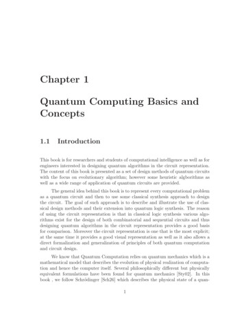
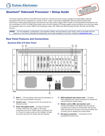
Product CategoryQuantum Videowall Processor Setup GuideThe Extron Quantum Elite 615 and 408 and the Quantum Connect are multi-window scalable and expandable videowallprocessors that can be configured for a variety of input, output, and window capabilities. Both processors feature highperformance video scaling technology that produces very high quality images. Both models can be populated at the factory withany combination of DVI-I or HDMI output cards, each of which supports 128 video graphic source windows, and with input cardsfor composite video or S-video, RGB or HD component video, DVI, HDMI, and SDI (including 3G-SDI, HD-SDI, and SD-SDI)sources.NOTE: For full installation, configuration, and operation details, see the Quantum User Guide, which is provided with theQuantum on the Extron Videowall Processing disc and is also available on the Extron website at www.extron.com.Rear Panel Features and ConnectionsQuantum Elite 615 Rear 55MEDIA I MEDIA II21ATTENTIONOBSERVE PRECAUTIONSFOR HANDLINGELECTROSTATICSENSITIVEDEVICESWARNINGSEE USER GUIDE BEFOREUSING THIS EQUIPMENTDO NOT REMOVE THIS PANELNO USER-SERVICEABLEPARTS INSIDEREFER ALL SERVICING TOQUALIFIED SERVICE PERSONNELTHIS EQUIPMENT MUST BEGROUNDED/EARTHEDDO NOT OBSTRUCTVENTILATION GRILLESDO NOT EXPOSE THIS EQUIPMENTTO RAIN OR MOISTURERear6aSlot 0 — If the processor slots are fully populated, aninput card can be placed in this slot.dControl card — Contains the RJ-45 connector forEthernet control.PS/2 keyboard and mouse card — ContainsPS/2 keyboard and mouse connectors to access theControl Panel for system setup.beInput and output cards — Contain composite,S-video, RGB/YUV, DVI, HDMI, or SDI inputconnectors and DVI or HDMI output connectors. Upto 15 input or output cards can be installed. At leastone input card and one output card are required.Media I and II, USB, and monitor card —Contains the Media I and Media II RJ-45 networkconnectors for access to remote QGE 100 sources,USB connectors for access to the Control Panel, anda monitor port to display the Control Panel.cfAC power connector — Connection for theprovided IEC power cord1
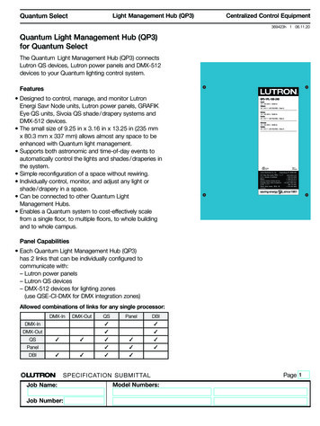
Quantum Setup Guide (Continued)Quantum Elite 408 and Quantum Connect Rear PanelThe illustration below shows a Quantum Elite 408. The Quantum Connect rear panel is the same, except that the two MediaRJ-45 ports on e are aAC power connector — Connection for theprovided IEC power corddUSB card — Contains USB connectors for access tothe Control Panel.bControl card — Contains the RJ-45 connector forEthernet control.ecInput and output cards — Contain composite,S-video, RGB/YUV, DVI, HDMI, or SDI inputconnectors and DVI or HDMI output connectors. Upto eight input or output cards can be installed; atleast one input card and one output card are required.Media I and II and monitor card — Contains theMedia I and Media II RJ-45 network connectors foraccess to remote QGE 100 sources (Elite 408 only),a PS/2 keyboard and mouse connector for accessto the Control Panel for system setup, and a monitorport to display the Control Panel.Installation StepsWARNING:Risk of electric shock. To avoid electric shock or product damage due to condensation, always let theQuantum become acclimated to ambient temperature and humidity for at least 30 minutes before switching it on. Thisis very important when you are moving the unit from a cold to a warm location.1.Disconnect power from all equipment.2.(Optional) Mount the unit to a rack using the supplied bolts (see theillustration at right).3.Connect the video inputs and outputs. Connect cables in any orderbetween source and display devices and the following rear panel ports asneeded:zzControl (Ethernet)zzDVI, RGB, HDMI, SDI, and video inputszzDVI and HDMI outputszzUSBzzRGB video monitorzzKeyboard and mousezzMedia 1 and Media II RJ-45 for QGE 100 networks (Elite models only)4.Connect power to the Quantum IEC connector.5.Power on all connected devices.6.Open the front access panel and set the Quantum power switch or switches to On.7.(Optional) Access the Control Panel and configure the IP address. A keyboard, mouse, and monitor must beconnected to the appropriate card to view and use the Control Panel.8.Install and set up the Quantum Control Software on your computer.9.Configure sources and displays for your videowall system using the Quantum Control software.NOTE:2Steps 8 and 9 can be performed without inputs, outputs, or other hardware being connected to the processor.
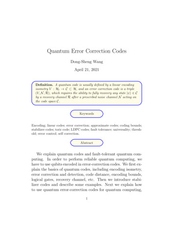
Product CategoryPowering On the Quantum ProcessorAfter all rear panel connections have been made and all connected devices are powered on, you are ready to power on theQuantum processor. Before powering on the system, ensure that the provided power cord is connected between the Powerconnector on the rear panel and an AC power source. Power switches are located on the front panel behind the access panel.To access the power switches, turn the panel latch one-quarter turn to the left, then grasp the latch knob firmly and pull the dooroutward and down.PSU Power SwitchesPower SwitchTo power on the Elite 615:1. Set the vertical PSU Power rockerswitches on both PSUs to I (On).OIzzPOWERQuantum Elite 615IOATTENTION:Both power supplyunits must be powered on at alltimes during unit operation.2.IOSet the horizontal Power switch to I.To power off the Elite 615, set the horizontal Power rocker switch to O (off).NOTE:It is not necessary to turn off the switches on the two PSUs. They can remain set to On.Quantum Elite 408 and Quantum ConnectzzTo power on the Elite 408 or Connect, press and release the front panel verticalPower rocker switch. While the system is powering up, the 0 in the LCD window to theright of the hard drive blinks. When the processor is completely powered up, the LCDstops blinking and remains lit steadily.zzTo power off the Elite 408 or Connect, press and hold the Power rocker switchuntil power is off (approximately 5 seconds).Power SwitchLCD WindowPOWERATTENTION:If your Quantum front panel contains a black rectangular Resetbutton below the Power switch, do not press it. Doing so could damage theoperating system.Using the Quantum Control PanelStarting the Control PanelThe Quantum processor is a host device with Windows XP embedded. The ControlPanel is a Windows-based program that is resident on the Quantum internal disk orflash drive and lets you perform certain setup tasks. To start the Control Panel:1.With the Quantum powered off, connect a PS/2 or USB keyboard and mouseto the USB or mini-DIN connectors on the rear panel.2.Connect a monitor to the 15-pin VGA connector on the rear panel Media card(Elite 615) or the Keyboard and Mouse card (Elite 408 and Connect).3.Power on the processor. The Quantum introductory screen is displayed.4.On the Quantum keyboard, press Ctrl F2 . The Control Panel main window opens (shown at right).Changing Network Settings1.On the Control Panel window, click Network Settings.2.On the Network Settings window, select the port to configure from the Select Network Connection drop-down menu.3.Enter the new IP addresses in the following panels as required:zzIP Settings: Enter any needed changes in these IP address fields; or select the DHCP Enabled check box to specifyautomatic detection of these addresses.zzMachine Name: If desired, enter a name of 1 to 15 characters for the processor (letters, numbers, and hyphens [-] only).zzDNS Settings: Enter any needed changes in these fields; or select the DHCP Enabled check box.zzWINS Settings: Enter any desired changes in these IP address fields.3
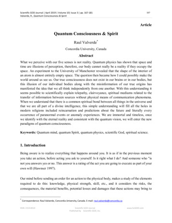
Quantum Setup Guide (Continued)4.Click OK to confirm the settings.5.A prompt appears stating that your changes will go into effect with the next reboot. Click Yes to reboot the processor.ATTENTION:Do not power off or reset the Quantum while it is rebooting.Using the Quantum Control SoftwareThe Quantum Elite and Quantum Connect software programs enable you to configure and control the Quantum from yourcomputer by creating a videowall project. Both control programs are provided on CD with the processor. This section provides anoverview to get you started using the software. For detailed information, see the Quantum Control Software User Guide, availableat www.extron.com.Connecting the Quantum to a ComputerFor you to use the software, your computer must be connected to the RJ-45 Control connector on the Quantum rear panel.zzIf using multiple videowall processors, connect straight-through cables from the computer Ethernet port to the hub or routerand from the hub or router to the Quantum Control port (indirect connection, shown below).Control PortEthernetHUB100BASE-TCONTROLMEDIA I MEDIA IIOther Quantum Elite Processorsor Network Sources/Devices1Quantum EliteControl NTIONOBSERVE PRECAUTIONSFOR ughCableWARNINGSEE USER GUIDE BEFOREUSING THIS EQUIPMENTDO NOT REMOVE THIS PANELNO USER-SERVICEABLEPARTS INSIDEREFER ALL SERVICING TOQUALIFIED SERVICE PERSONNELTHIS EQUIPMENT MUST BEGROUNDED/EARTHEDIndirect ConnectionzzDO NOT OBSTRUCTVENTILATION GRILLESDO NOT EXPOSE THIS EQUIPMENTTO RAIN OR MOISTUREQuantum ProcessorIf using only a single videowall processor, you can connect a crossover cable from the computer to the Quantum Controlport (direct connection).Installing and Starting the SoftwareTo install and run the appropriate software on your computer:1.Insert the Quantum CD in the disk drive and navigate to the CD drive.2.Open the folder for your Quantum product.3.Open the folder for your Quantum model.4.Double-click on the file named Quantum Elite SetupVn.nn.exe or Quantum Connect SetupVn.nn.exe.5.Follow the instructions on the wizard screens to complete the software installation.6.Open the software program by clicking the Quantum icon on your desktop or by clicking Start All Programs Extron Electronics Quantum Elite (or Connect) Quantum Elite (or Connect). The main application window opens.Configuring the SystemTo use the Quantum software to configure and control the processor, start by setting up a project (presentation), in which youdefine the processor, select or create a layout, set up video sources, and create multiple scenes. For best results, perform thefollowing setup procedures in the order they are presented in this guide.Choosing a display processorBefore the software can control a Quantum processor, it must detect and be connected to the processor as follows:41.On the taskbar (the left column of the main window), click the Choose Display Processors button (shown at right).The Choose Display Processors workspace window opens.2.Click the Detect button (shown at right) on the toolbar or select Detect from the Detect menu.3.Select the Connect check box to the right of the IP address of the processor to which you want to connect.
Product CategoryChoosing a layoutThe target display can be a single screen or multiple screens interlocked to form a larger display area. You can select one of thedefault layouts or create a new one. The layout you select is applied to all scenes in your project.1.On the taskbar, click the Choose Layout button (shown at right).2.On the Choose Layout Workspace window, click one of the layout diagrams on this screen, create a new layout, orchange an existing one:a.From the Layouts menu, select New.b.On the New Wall Layout window, entera name for the layout in the Name field.c.On the Wall layout panel, enter orselect the number of screens in therows and columns of the videowall.d.From the Output Mode menu, select aresolution for each screen in the layout.e.From the HDMI Format menu, selectwhether the output will be formatted asDVI, HDMI, or automatically, based onthe EDID of the display.f.From the HDCP Notification menu,select whether to enable or disablenotification of HDCP content.g.If the layout contains more than onescreen, select either the MullionAdjustment radio button or the EdgeBlend Compensation button andparameters to specify compensation for the areas between the screens.h.Click OK to save the new layout.3.Right-click a screen in the selected layout (usually starting with the top left screen) and select Change Screen Processor IPfrom the drop-down menu.4.Make selections on the Set options for screen 1 window (shown at right):a.Select the IP address of your Quantum processor from the Processor IPdrop-down menu.b.From the Available Outputs drop-down menu, select an output card toassign to this screen as the primary output.c.In the Second Output panel, select how the secondary output will beassigned:d.5.zzHorizontal — The secondary output is assigned to the screen immediately to the right of the primary output.zzVertical — The secondary output is assigned to the screen immediately below the primary output.zzDo not assign — No secondary output is assigned; only the primary output is used.Click OK to confirm the assignments.Repeat steps 3 and 4 for each remaining screen in the layout.Setting up sourcesEach source to be used in a project must have a corresponding source definition in the Quantum Control software. For you tocreate a source definition, the Quantum must be connected to the computer on which the control software is installed. Use theQuantum Control Software to set up source definitions as follows:1.On the taskbar, click the Set Up Sources button (shown at right).2.In the source explorer tree in the left pane of the Set Up Sources workspace, right-click Display Processors andselect Detect Sources from the drop-down menu that appears.3.On the Detect Quantum Sources window, click the Full Detect button, then click Yes on the confirmation prompt thatopens. A list of source types is added to the source explorer tree, based on the cards installed in the processor.NOTE:To customize sources, see “Setting Up Sources” in the Quantum Control Software User Guide.5
Creating a scene (preset)A scene, or preset, is a set of one or more windows in which video sources are displayed on a videowall. Window layoutparameters, including size, position, and content of the windows are stored in the scenes. Scenes can be recalled anddisplayed in any order. To create a new scene:1.On the taskbar, click the Scene Design button (shown at right) to display the scene Design workspace.2.On the Scene Properties toolbar, click the New Scene button (shown at right). The Scene Properties window openswith the Properties tab displayed (see the illustration below right).3.In the Scene Title field, enter a title for the new scene.4.Make changes to the other properties in this dialog as needed.5.When finished, click OK. The Scene Properties window closes, and the newscene title is displayed in the Scene palette (far right panel) of the SceneDesign screen.6.Add windows to the scene, as described in the next section.Adding windows to a sceneIn the Scene Design workspace, the videowall is represented by a virtual canvas,on which windows can be placed. The windows are indicated by rectangles in theselected scene.See the Quantum Control SoftwareUser Guide for details on these andother window properties that you canset.To add a window to a scene:1.From the source pane, left-click and drag a source icon to the desired location on the virtual display.2.If desired, click on the window and modify it as follows:zzResize: Click on the window and drag the resizing handles on the window border.zzMove: Click within the window and drag it to the desired location. If you do not want the window to snap to the grid,deselect Snap Grid on the Grid menu.zzResize to fill the display area: Right-click the window and select Full Screen from the drop-down menu.zzSet to a specific size: Right-click on the window and select Adjust Position and Size from the drop-down menu. Onthe Window Size & Position dialog, enter the desired settings.zzChange the source in an existing window: Right-click and drag a source icon to the desired window.Extron HeadquartersExtron EuropeExtron AsiaExtron JapanExtron ChinaExtron Middle EastExtron KoreaExtron India 800.633.9876 Inside USA/Canada Only 800.3987.6673Inside Europe Only 65.6383.4400 65.6383.4664 FAX 81.3.3511.7655 81.3.3511.7656 FAX 86.21.3760.1568 86.21.3760.1566 FAX 971.4.299.1800 971.4.299.1880 FAX 82.2.3444.1571 82.2.3444.1575 FAX1800.3070.3777(Inside India Only)Extron USA - WestExtron USA - East 1.714.491.1500 1.714.491.1517 FAX 1.919.850.1000 1.919.850.1001 FAX6 31.33.453.4040 31.33.453.4050 FAX 2013 Extron Electronics — All rights reserved. All trademarks mentioned are the property of their respective owners. 91.80.3055.3777 91.80.3055.3737 FAXwww.extron.com68-2010-50Rev. B 06 13
Quantum Videowall Processor Setup Guide . Panel is a Windows-based program that is resident on the Quantum internal disk or flash drive and lets you perform certain setup tasks. To start the Control Panel: 1. With the Quantum powered : off, connect a PS/2 or USB keyboard and mouse