Transcription
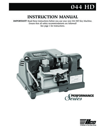
044 HDINSTRUCTION MANUALIMPORTANT! Read these instructions before you use your new 044 HD Key Machine.Ensure that all safety recommendations are followed!See page 3 for instructions.
This manual applies specifically to the 044 HDPerformance Series key machine. It properly identifiesyour model and assures you will receive correct parts, ifand when you require replacement parts. Retain thismanual in a safe place. If ownership of this machine istransferred, this service manual should accompany themachine.When seeking service information about this machine,refer to Model No. 044 HD and the part number desired(see pages 6 to 8). Note that many parts are not interchangeable with other KABA ILCO machines.CONTENTSWarranty .2Safety information .3Introduction / unpacking .4Operating parts (illustrated).5Operating parts identification (names and part numbers) .5Exploded view .6Exploded view parts list / unpacking / test keys .8How to duplicate keys .9The cutting operation / replacing the cutter .12Adjustments .13ONE YEAR LIMITED WARRANTYKABA ILCO warrants to the original buyer of anynew model 044 HD machine that it will repair orreplace, at its option, any part of any machine whichproves, to the reasonable satisfaction of KABA ILCO,to have defects arising from the faulty manufactureof the machine or from defective material or components, during a period of one (1) year from the dateof shipment of the machine by KABA ILCO, provided that the machine is returned by prepaid transportto KABA ILCO or to its authorized representativebefore the expiry of the warranty period togetherwith a detailed description of the alleged defect(s).KABA ILCO may, at its discretion, elect to refund thepurchase price allowable to the part affected, or toissue a credit if the price therefore remains unpaid.KABA ILCO sells precision-made machines. Thebuyer assumes all risks, and KABA ILCO shall not beliable for any reason, if the machine has been subjected to improper installation, improper use,improper or inadequate maintenance, negligence, ifany unauthorized modification or alteration is madeto the machine, or in case of accident. For greatercertainty, any machine not operated in accordancewith KABA ILCO printed instructions or operatedbeyond its rated capacity shall not be covered by thisor any other warranty.2Any and all warranties made by KABA ILCO on anymachine, product, or component thereof shall be effective only if and for so long as the buyer complies withall payment obligations pursuant to the buyer’s accepted and acknowledged order. Failure to meet such payment obligations shall void all warranties and notextend the period of time for which such machine,product of component thereof is warranted irrespectiveof whether or not payment is eventually made.These warranties are in lieu of and not in addition toany other warranty of condition, expressed or implied,including without limitation merchantability, fitnessfor a particular purpose or latent defects. The buyerreleases KABA ILCO from any liability for any reasonother than a breach of its warranties hereunder.The liability of KABA ILCO shall in no case, including negligence, exceed the purchase price of thedefective machine, nor shall KABA ILCO be liable forany personal injuries, property damage or consequential damages.Use only genuine KABA ILCO replacement parts onthis machine!Serial number :
WARNING – SAFETY NOTICEIMPORTANT - Please read carefully before operating machine.Safety begins with education, and continues with properapplication. All personnel who operate your machineshould read the supplied Operator’s Manual for information on how to properly operate it. The likelihood of accidents and miscuts will be greatly reduced.General safety Safety glasses must be worn to reduce the possibilityof eye injury while operating or in the immediatevicinity of key cutting equipment. Always turn machine off before making adjustmentsor inserting or removing keys. Machine should be located in an area accessible onlyby authorized operators. Location must be such thatcustomers and other personnel are not subject topotential injury from “flying chips”. Do not defeat safety features built into your machine.Removal or modification of safety shields, cutterguards, and other safety devices should be strictly forbidden. At no time should the mechanically-driven parts ofthe machine be touched while it is in operation. Theoperator should take care to ensure that loose-fittingclothing, long hair, etc. are kept from the area ofmachine operation. Your machine has been specially designed and builtfor key cutting purposes only and should be operatedaccording to the Operator’s Manual. All other uses arestrongly discouraged as potentially dangerous, andshould not be attempted! Such use will immediatelyvoid the machine’s warranty. Some states have specific age restriction concerningthe operation of certain types of equipment. Checklocal and state ordinances for compliance.Electrical safety (115 Volt models) Your machine is designed to operate using 120 Volt A. C. 60 Hz. electrical current. It issupplied with a three-prong power plug which shouldbe used with a properly grounded three-prong outletonly. Do not defeat the safety purpose of the plug bymodifying or using with non-grounded outlets! To reduce risk of fire or electrical shock, do not exposeor operate machine in damp or wet locations. Electrical problems should be referred to qualifiedrepair technicians. If the machine is under warranty,contact KABA ILCO at the address printed on thecover. (KABA ILCO also offers repair service for outof-warranty machines. Contact KABA ILCO fordetails.) Always unplug the machine before removing the hoodor changing the cutter wheel.Grounding instructions In the event of a malfunction or breakdown, grounding provides a path of least resistance for electric current to reduce the risk of electric shock. This machineis equipped with an electric cord that has an equipment-grounding conductor and a grounding plug. Theplug must be plugged into a machine outlet that isproperly installed and grounded in accordance withall local codes and ordinances. Do not modify the plug provided - if it will not fit theoutlet, have the proper outlet installed by a qualifiedelectrician. Improper connection of the equipment groundingconductor can result in a risk of electric shock. Theconductor with insulation that has a green outersurface (with or without yellow stripes) is the equipment-grounding conductor. If repair or replacement ofthe electric cord or plug is necessary, do not connectthe equipment grounding conductor to a live terminal. Check with a qualified electrician or service personnelif the grounding instructions are not completelyunderstood, or if in doubt as to whether the machineis properly grounded. Use only 3-wire extension cords that have 3-pronggrounding plugs and 3-pole receptacles that acceptthe machine’s plug. Repair or replace damaged or worn cords immediately.3
INTRODUCTION / UNPACKINGCongratulations!You’ve purchased a superior key cutting machine.The Model 044 HD manual Performance Series keymachine you've just purchased incorporates the latestimprovements in design for key duplicating machines ofits type.This machine features exclusive four-way vise jawsdesigned to accommodate virtually any standard cylinderkey without the need for adapters.Even double-sided automotive keys can be duplicatedwith ease; the four-way jaws include stations ideally suited to gripping these keys and is capable of gripping themin the groove or milling for enhanced clamping performance when necessary.Accurate, easy to operate and maintain, the model 044 HDdelivers excellent performance at an economical price!Unpacking instructionsYour 044 HD key machine has been shipped to you in asturdy, specially cushioned container to prevent the possibility of damage during handling and shipment. Oncethe machine is removed from the carton, it should be setup on a level workbench and wiped free of all rustproof-ing oil. The machine is adjusted at the factory and testkeys have been cut on it, but it is recommended that youcheck the adjustments to make sure they have notslipped or shifted during transit (see page 13 “Adjustingfor depth of cut”).SafetyThe 044 HD has been engineered to duplicate cylinder(paracentric) keys. It is not intended or designed for anyother purpose. The machine operator assumes all liability when using this machine in a manner inconsistent withits stated design purpose. Refer to page 3 for completesafety information before operating the machine.when in the vicinity of the machine while it is being operated. Protective eye wear prevents injuries! The machineshould be turned off before loading or unloading keys.When the key machine is operating, be careful not tocontact the vise jaw or carriage against the cutting wheelas this will cause damage to the cutter, jaw, or carriage.KABA ILCO strongly recommends the use of protectiveeye glasses or goggles when operating this machine, orCAUTION!4DO NOT DESTROY OR DISCARD THIS SPECIAL SHIPPING CARTON.STORE IT CAREFULLY IN A SAFE PLACE. THIS CARTON SHOULD BE USEDWHENEVER THE MACHINE IS MOVED OR SHIPPED.
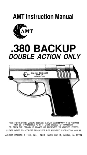
OPERATING PARTSSafety hood assemblyKey gaugeSafety shieldDepthDialNylonbrushCutter guideWing nutCarriageCarriageshaftOn / Offpower switchVise jawassemblyOperating parts identificationPart no.Identification024B-1025-3X025-8CarriageVise jaw assemblyWing nut045-23P-CU20814-00-51Carriage shaftP-CU20 cutterNylon brush045-49045-55A040-56Cutter guide (stylus)Adjusting screwKey gauge025-62A045-86X045-87On/Off switchSafety hood assemblySafety shield5
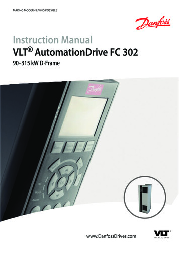
EXPLODED VIEW6
EXPLODED VIEW7
EXPLODED VIEW PARTS LISTRefer to pages 6-7 for illustrationRef.Part no.DescriptionRef.Part rriageCarriage assemblyCarriage studVise jaw assembly (Super Jaw 3)798486X87024B-79024B-84044HD-86X044HD-87Key gauge springClipSafety hood assemblySafety shield46X89X025-4025-6X025-8040-9XVise jaw springThrust bearing setWing nutCarriage handle045-89025-90024B-91024B-92#10 LockwasherNut, #10-32Power cord3 wire motor cable20212332040HD-20025-21044HD-23024B-32Cutter shaft bearingsCarriage shaft bushingCarriage shaftButton head. screw, 10-24 x 3 8"100101106109040HD-100025-101040-106025-109Cutter spacer; rightMotor pulley set screwChip trayBearing 40HD-41814-00-51024-45025-46ACutter nut, N-4Cutter spacer; leftP-CU20 cutterCutter shaftCutter shaft pulley (2”)Nylon brushBrush bolt washer, 5 16Hex head screw, 5 16-18 x 3 150040-151025-160045-163025-171Wave washerLocking nut (8-32)Power cord strain reliefSwitch screw (6-32 x 1/4")Set screw (8-32 x 3/8")Caution labelHood ScrewCutter pulley set screw, 3 8" -1847484950025-47040HD-48045-49040-50Motor pulley 2" - 3LV-Belt, 3L160Cutter guide (stylus)Carriage stop181182183184024B-181024B-182040-183040-184Key Gauge Spacer - LeftKey Gauge Spacer - Right1/4-20 Lockwasher1/4-20 Hex Nut52535455A040-52045-53A045-54045-55ASocket hd. screw 8-32 x 1-1/2"Cutter guide binding washerCutter guide binding screwAdjusting screw186187188189045-186045-187045-188045-1896-32 x 3/8" set screwdoweldowel springAdjustment gaugegauge bracketgauge dowel pingauge ter guide label#10 flat washer10-32 x 1/2" Button hd. screw7/16-14 x 3/4" set screw025-60025-61025-62A044HD-65Cap screw, 8-32 x 1 2"Circuit Breaker, ETA 1658On/Off switchMachined base199IMNS045-199044HD-IM025-2401/2-20 x 1/2" set screwInstruction manual220V 1 4 HP motor040-68040-70040-74040-75Electrical coverRubber mountTruss head screw, 8-32Motor, 1 4hp,115V606162A6568707475889909192
HOW TO DUPLICATE KEYSOperating HandlesProper key cutting techniquesThe 044 HD key machine is shipped completely assembled except for the carriage handle and the lever handle.Upon unpacking the machine, locate the carriage handleand thread it into the carriage in the area directly abovethe trigger assembly. Then, cut the nylon band holdingthe carriage rigid and insert the lower end of the leverhandle into the hole in the pinion shaft (located at thefront of the machine on the left side). Tighten the setscrew on the front of t pinion shaft to secure the leverhandle. Refer to page 5 if unsure of handle placement.Even though your 044 HD key machine is designed tomake key cutting fast, efficient and accurate, operatorskill is important. The actual mechanics of placing keyswithin the vise jaws is simple to learn, but there are somebasics that must be followed. A properly adjusted keymachine used by someone who ignores good key cuttingtechniques will NOT produce a good key. The way a person clamps a key into the vise jaws is critical to the accuracy of the duplicated key.Test keysHere are some important operating tips:1. Vise jaws - clean them regularly so that no metalchips lie under the keys. It is essential that bothkeys lie flat across the entire width of each visejaw. Neither key should be tilted.2. Do NOT use pliers or other tools to tighten the visejaws. Firm hand pressure is sufficient.3. Keep the carriage shaft free of metal chips. A thin filmof oil can be applied to it. The carriage should be freeto move without binding.4. NEVER touch the shoulder of a key to the side of thecutter guide. This will cause the shoulder of the keyblank to touch the side of the cutting wheel. Whenthis happens, some of the metal will be cut away fromthe shoulder of the key blank. If the resulting duplicated key is duplicated two, three, four times over, anerror will accumulate and cause a non-operating key.Do not grind away the shoulder.5. Don't run the cutter into the vise jaw; this will dull thecutter, and reduce cutter efficiency.6. Keep the cutter clean. Don't let any foreign objects orinstruments blunt it. This cutter is a precise cuttingtool and should be handled with care.7. Lubrication requirements for your new “HD”Performance Series key machine are minimized throughthe use of sealed, permanently lubricated cutter spindlebearings. The carriage shaft however, should be inspected on a routine basis, and wiped with a dry, clean clothto remove any chip buildup that occurs. After cleaning,application of a dry film lubricant is recommended formaximum service life; spray type lubricants that drycompletely once applied are fine. Depending on usage,the machine’s 1/4 hp motor may require lubricationonce annually. Refer to the label on the motor for lubrication details and recommended interval.A series of cut keys are supplied with your machine. Thesekeys were cut on your machine and represent the result ofour quality inspectors' work before approving yourmachine for shipment. The keys are reproductions of factory dimensioned pattern keys and are accurate to .002" orless. Save these keys and use them as standards to checkthe accuracy of cuts in the keys you make. Duplicating akey and then using a key micrometer or caliper to comparethe actual depth of the cuts on both the duplicate and thepattern key will allow you to see if your machine is cuttingtoo deep or too shallow, thus indicating that an adjustment of the cutter guide is necessary.Remember - the real purpose of a duplicate key is tooperate the lock for which it was intended. If customersreturn keys, you should reexamine your cutting techniques and adjustment of the machine.9
HOW TO DUPLICATE KEYSGeneral key duplication proceduresUsing the four-way vise jaws (cont.)WARNING: Do not install or remove keys unless theoff/on switch is in the OFF position! Always wear eyeprotection when operating this machine!To obtain the best gripping action possible, it is necessary to assure that the proper vise jaw position is selected for each key you duplicate. The vise positions areexplained below and proper usage shown in figure 2.There are four procedures that the machine operator performs to insure proper duplication of a key:1. Selection of the proper key blank. Compare the head,length, and key blank's cross section (width, angle,and location of grooves) with the key to be duplicated to assure that a proper match has been made.2. Ensuring both four-way vise jaws have been placed inthe proper position for the type of key to be duplicated. See “Using the four-way vise jaws” section of thismanual.3. Proper alignment of the pattern key and blank keywithin the vise jaws. See “Aligning keys in the visejaws”.4. Actual duplication of the pattern key; which can beproperly accomplished only after the previous stepsare performed.Standard - for holding regular cylinder keys, such ashouse keys, single sided automotive keys, padlock keys,with one or two shoulders.Narrow - for holding the 1092B and other narrow widthkeys.Wide - for holding the Ford double-sided keys and similar types, either primary or secondary. When positioningthe keys in the vise jaws, lay the key so that its centerledge is flat against the top surface of the jaw.X - Ideal for holding most double-sided conveniencekeys used on most current automobiles. Grip these keysby the grooves rather than the blade edge where the cutsare located (see Fig. 2).Figure 2Using the four-way vise jawsYour 044 HD is equipped with the KABA ILCO versatileFour-way, Super Jaw 3 vise jaws. They feature fourunique clamping surfaces to securely grip virtually anytypical cylinder key (see Fig. 1).Super Jaw 3vise jaw showngripping a typicalautomotive keyFigure 1Rotate bothjaws as a setUsing standard positionUsing X positionUsing wide positionUsing narrow positionTo reposition the vise jaws, as from Standard to Wide,first loosen the wing nuts. Then lift upward on the topand bottom of each vise jaw as a complete unit to raisethem above their seat in the carriage. Rotate the jawsuntil the chosen vise position is facing toward the rear ofthe machine and lower the jaws back into contact withthe carriage. Both left and right vise jaws should be rotated to the same position.10
THE CUTTING OPERATIONAligning keys in the vise jawsKeys with shouldersWARNING: Do not install or remove keys unlessthe off/on switch is in the off position.Both the pattern key and the key blank must be properlyaligned and securely clamped in the vise jaws prior to duplication. The correct procedure to do this follows.1. Move the carriage lever to the left as far as possible (SeeFig. 3).Figure 3Figure 47. Check to ensure that the pattern key and blank key’sshoulder are snug against the key gauge and both keyspositioned level (not tilted) in the vise jaws. Return keygauge to the “up” position. The key is now properlyaligned for duplication.Aligning keys in the vise jawsKeys without ShouldersOn keys that don’t have a conventional shoulder, such asthe Ford double-sided key, the tip of the key is used as thealigning point. With keys of this type follow this procedure.1. Assure that both vise jaws are rotated to the correct position for the type of key being duplicated.2. Position the key blank in the right hand jaw. For most tipgauged automotive keys, position the blank so that thetip is roughly 1/4” left of the jaws right edge. Tighten thejaws wing nut securely.3. Move the carriage lever to the left so that the key gauge’sright hand “finger”, with gauge lowered, is just forwardof the key blank’s tip.2. Assure that both vise jaws are rotated to the correct position for the type of key being duplicated.3. Place the key blank in the right hand jaw. Position it sothat it is parallel with the front portion of the jaw (see Fig.4). Tighten wing nut lightly.4. Swing key gauge down to rest on the blade of the keyblank. Slowly move carriage lever clockwise to the rightuntil the should of the key blank butts up against theedge of the key gauge (See Fig. 5).4. Insert the customer’s key (pattern key) in a similar manner in the left hand jaw. Then position both the customer’s key and the key blank so that their tips are bothin direct contact with the left edge of the key gauge fingers (See Fig. 6).Figure 6TipTip5. Use index finger to press down on the front edge of thekey blank while loosening wing nut. Retighten securelyafter assuring that the key blank is contacting key gaugeand is properly seated in the vise jaw.6. Position pattern key in the left vise jaw repeating the procedure described in step 4.Figure 5ShoulderShoulder5. After both the customer’s key and blank key are aligned,left key gauge to it’s raised position.6. If a key is cut on both sides, after duplicating “side one”rotate and proceed with “side two” using the same alignment procedure. In the case of Ford keys as well as motdouble-sided European and Japanese double sidedkeys, only the blank needs to be rotated as the cuts arethe same on both sides.Key GuageLift Up7. Refer to page 12 for additional information covering theactual key duplication process.11
THE CUTTING OPERATION / REPLACING THE CUTTERGeneral Operating SequenceWARNING: Do not install or remove keys unlessthe off/on switch is in the off position. Always weareye protection when operating this machine.1. Rotate both vise jaws to the station suitable for thekey being duplicated.2. Insert the blank key and pattern key into the vise jawsusing the appropriate method described under“Aligning Keys in the Vise Jaws”. Be sure that bothkeys are laying level in the vise jaws and are not tilted.3. After the keys areFigure 7aligned, move the carriage lever to the right(clockwise) until thecutter guide is slightlyleft of the cut closest tothe head of the patternkey (see Fig. 7)5. Press the off/on switchto the “on” position.6. Push down on thecarriage handle whilepulling out on the carriage trigger (See Fig. 8).Figure 8CarriagehandleTrigger (pull out torelease)This will allow you to ease the carriage up into cuttingposition. Take care to ensure that the carriage doesnot “slam’ forward as this will result in probable cutter damage. Remember, best results are obtained ifthe cutter guide makes initial contact slightly left ofthe cut closest to the head of the pattern key. Do notpermit the cutter to touch the should of the key blank.126. The carriage movement is controlled by the carriagelever. Using slow moderate speed, smoothly move thecarriage lever to the left (counter clockwise). Avoidusing an erratic, jerking movement! Once the cutter isat the tip of the key, move the carriage to the right bymoving the carriage lever clockwise. This will result ina second cutting pass over the key blank. STOPbefore cutter contact with the shoulder of the blankoccurs.7. Press the off/on switch to the off” position and removefinished key by pushing down on the carriage handleuntil the trigger clicks into place. Then loosen wing nutto remove duplicate key.8. To deburr the key, turn the machine on, and position thecut key lightly against the rotating deburring brush.Replacing the CutterThe P-CU20 cutter used on this machine is .250 in diameter, .093” thick and has a 1 2” hole. It’s a milling cutter,made out of high speed steel. It has a flat left side, whichis excellent for making deep cuts, when these cuts arenext to the shoulder, such as on GM, Chicago, etc. Nowarranty is placed on the cutter, operators should treat itwith care and avoid harsh usage. Do not force the carriage up, causing the key blank to bang into the cutter,and do not apply heavy pressure when cutting. Also, donot let the cutter run into the vise jaw; this will dull thecutter quickly.As with any metal cutting instrument, the P-CU20 willdull with usage. There are three ways to tell when a cutter is dull and requires replacing:1. Time - a dull cutter takes longer to make the cuts.2. Sound - a dull cutter will emit a shrill sound as it runsacross the key blank.3. Burrs - a dull cutter will not cut away the metal butwill roll it away. When this occurs, there will be abuildup of metal burrs on the underside of the key. Ifthis buildup is heavy, the cutter is dull. A sharp cutterleaves little or no burrs.To replace the cutter, use two wrenches, one 3 4" wrenchfor the cutter nut and one 1 2" wrench for the cutter shaft.Set the two wrenches in position and loosen the cutternut. Note that the cutter nut has a reverse thread andturns downward to loosen. Remove the spacer washersand the dull cutter. Install the new cutter, the washers,and the nut.
ADJUSTMENTSAdjusting for depth of cutTo ensure safety, UNPLUG machine from its powersource before adjusting for depth of cut. It's imperativethat the key guide and the cutter be in the same plane,that is, aligned to each other. If the cutter guide protrudesfurther than the cutter, the resulting cuts in a key blankwill be too shallow and the duplicate key will not work.Likewise, if the cutter guide is behind the cutter, the cutsin the key will be too deep (see Fig. 9).Figure 9Adjustment iscorrect whenboth key blankstouchTo check the depth adjustment, insert two identical keyblanks into the vise jaws, setting them flat in each vise.(It is not necessary to align the blanks.) Then, raise thecarriage, positioning the left blank against the cutterguide and the right blank against the cutter. Next, turnthe machine pulley by hand and note the right key blank.The cutter should just barely graze the key blank whenthe adjustment is correct.No cutter is perfectly round so make one complete rotation of the cutter before changing adjustment. There willFigure 10Bindingscrewbe a high point on the cutter; the adjustment should bemade to the high point. If the cutter does not touch thekey blank after one rotation, proceed to change the adjustment.To adjust the cutter guide,loosen the binding screwon top of the cutter guideslightly. (see Fig. 10 &Binding 11). Once you have loosPlate ened this screw, the depthadjustment dial can beBinding rotated to the left (toScrew decrease depth of cut) orto the right (to increaseCarriage depth of cut). Again,Stopproper adjustment will beachieved when the cutterjust barely grazes the key blank before it while the cutter guide is in contact with the other key blank. Retightenthe binding screw once the calibration process is completed. Recheck after tightening to assure that adjustment did not shift.Figure 11DepthDialEach calibration mark on the depth adjustment dial isequivalent to approx. .0015” (1 1/2 thousandths of aninch). As you can see, this system can allow for very precise adjustment of your new key machine. In fact, if youhave a key micrometer or dial caliper available, you canadjust your machine with “factory accuracy”. To do this,you would simply duplicate a key and measure cuts onboth the “pattern key” and the duplicate key for comparison. This would show any deviation that existed andwhether the duplicate cuts were too deep or too shallowand by how much. With this information, you can usethe depth adjustment dial on your machine to calibrateyour machine for best possible accuracy. This is veryimportant as many locks are designed with close fit tolerances and the keys you duplicate are often themselvescopies; functional but just barely so. The more accurateyour key machine is adjusted, the closer your duplicateswill match their originals, resulting in fewer non-functional miscuts!It is very important to understand that adjusting yourmachine is not a “one time” procedure. As the cutter onyour machine wears down, the machine must be adjusted to compensate. It is good shop practice to check youmachines’ depth adjustment every 2-4 weeks, basedupon your store’s key cutting volume and readjust asnecessary. You will find that re-calibration is seldomneeded, but by checking and correcting BEFORE customers begin returning miscut keys, you will create a reputation for your store as a “good place” to have keysduplicated.Depth AdjustmentDialCarriage stopadjusting screw13
ADJUSTMENTSAdjusting for spacingThere is no adjustment for spacing. However, if a keygauge assembly is ever replaced, the key gauge must befitted to the machine after it has been installed. To dothis, first install a pattern key and key blank and alignthese against the cutter guide and cutter. Then lower thekey gauge and file the appropriate finger of the gauge toallow contact with the shoulder of both keys.Adjust the Carriage StopThe purpose of the carriage stop is to prevent the cutterfrom hitting into the right vise jaw. The stop is a nut andbolt and is adjustable. To check the adjustment, raisecarriage (without keys in vise jaws) and rotate the cutterby hand. The cutter should not contact the vise jaw.When the carriage stop is properly adjusted, thereshould be a space of .008" between the vise jaw and thecutter (this is about the thickness of an ordinary business card). Do not allow a greater distance since thismany affect the depth of cut.CleaningYour machine should be kept clean of all filings anddust. The most critical areas are the carriage jaws andshafts. A one inch paint brush is ideal to brush theseareas of the machine. The shafts should be wiped periodically with a lightly oiled cloth. We suggest brushingthe jaws often as even a single filing can alter the accuracy of the machine.14
15
Kaba Ilco Corp.P O Box 2627 (27802)400 Jeffreys Rd., Rocky Mount, NC 27804Tel.: (252) 446-3321 Fax: (252) 446-4702www.kaba-ilco.com16Printed in USA125190
You've purchased a superior key cutting machine. INTRODUCTION / UNPACKING 4 Your 044 HD key machine has been shipped to you in a sturdy, specially cushioned container to prevent the pos-sibility of damage during handling and shipment. Once the machine is removed from the carton, it should be set up on a level workbench and wiped free of all .