Transcription
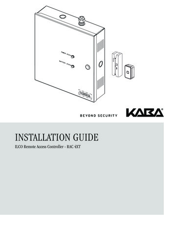
INSTALLATION GUIDEILCO Remote Access Controller - RAC 4XT
CONTENTS1.0Introduction and Disclaimers . . . . . . . . . . . . . . . . . . . . . . . . . . . . . . . . . . . . 22.0 Product Description . . . . . . . . . . . . . . . . . . . . . . . . . . . . . . . . . . . . . . . . . . . 32.12.2Features . . . . . . . . . . . . . . . . . . . . . . . . . . . . . . . . . . . . . . . . . . . . . . . . . . . . . . . . . . . . . . . .Components . . . . . . . . . . . . . . . . . . . . . . . . . . . . . . . . . . . . . . . . . . . . . . . . . . . . . . . . . . . . .2.2.1 Controller box . . . . . . . . . . . . . . . . . . . . . . . . . . . . . . . . . . . . . . . . . . . . . . . . . . . . . . .2.2.2 Card Readers . . . . . . . . . . . . . . . . . . . . . . . . . . . . . . . . . . . . . . . . . . . . . . . . . . . . . . .2.2.3 Locking Devices . . . . . . . . . . . . . . . . . . . . . . . . . . . . . . . . . . . . . . . . . . . . . . . . . . . . .2.2.4 Optional Peripherals . . . . . . . . . . . . . . . . . . . . . . . . . . . . . . . . . . . . . . . . . . . . . . . . . .3445553.0 Checklist and Exploded Views . . . . . . . . . . . . . . . . . . . . . . . . . . . . . . . . . . . 63.1 Parts and Tools List . . . . . . . . . . . . . . . . . . . . . . . . . . . . . . . . . . . . . . . . . . . . . . . . . . . . . . . . 63.2 Exploded View . . . . . . . . . . . . . . . . . . . . . . . . . . . . . . . . . . . . . . . . . . . . . . . . . . . . . . . . . . . 84.0 System Installation Overview . . . . . . . . . . . . . . . . . . . . . . . . . . . . . . . . . . . . 94.1Pre-Installation Procedures . . . . . . . . . . . . . . . . . . . . . . . . . . . . . . . . . . . . . . . . . . . . . . . . . .Step 1: Identify a secure location for the RAC 4XT enclosure . . . . . . . . . . . . . . . . . . . . . . . .Step 2: Identify location(s) for card readers and peripherals . . . . . . . . . . . . . . . . . . . . . . . . .Step 3: Set the desired access delay . . . . . . . . . . . . . . . . . . . . . . . . . . . . . . . . . . . . . . . . . .Step 4: Install strain relief . . . . . . . . . . . . . . . . . . . . . . . . . . . . . . . . . . . . . . . . . . . . . . . . . . .999994.2Installation & Wiring Procedures . . . . . . . . . . . . . . . . . . . . . . . . . . . . . . . . . . . . . . . . . . . . . .Step 5: Mounting the RAC 4XT enclosure . . . . . . . . . . . . . . . . . . . . . . . . . . . . . . . . . . . . . . .Step 6: Mounting & wiring card reader(s) . . . . . . . . . . . . . . . . . . . . . . . . . . . . . . . . . . . . . . .Step 7: Connect peripheral wiring . . . . . . . . . . . . . . . . . . . . . . . . . . . . . . . . . . . . . . . . . . . . .Step 8: Relay Expansion Board outputs wiring . . . . . . . . . . . . . . . . . . . . . . . . . . . . . . . . . . .Step 9: Power adaptor connection . . . . . . . . . . . . . . . . . . . . . . . . . . . . . . . . . . . . . . . . . . . .1011111214155.0 Settings and Operation . . . . . . . . . . . . . . . . . . . . . . . . . . . . . . . . . . . . . . . . . 165.15.25.35.45.55.65.75.85.9Testing . . . . . . . . . . . . . . . . . . . . . . . . . . . . . . . . . . . . . . . . . . . . . . . . . . . . . . . . . . . . . . . . .Hotel ID Initialization . . . . . . . . . . . . . . . . . . . . . . . . . . . . . . . . . . . . . . . . . . . . . . . . . . . . . . .Hotel ID Re-initialization . . . . . . . . . . . . . . . . . . . . . . . . . . . . . . . . . . . . . . . . . . . . . . . . . . . . .Programming and Auditing . . . . . . . . . . . . . . . . . . . . . . . . . . . . . . . . . . . . . . . . . . . . . . . . . .Battery Back-up Replacement . . . . . . . . . . . . . . . . . . . . . . . . . . . . . . . . . . . . . . . . . . . . . . .New Battery Back-Up Installation . . . . . . . . . . . . . . . . . . . . . . . . . . . . . . . . . . . . . . . . . . . . .Power Failure . . . . . . . . . . . . . . . . . . . . . . . . . . . . . . . . . . . . . . . . . . . . . . . . . . . . . . . . . . . .Loading Recommendations . . . . . . . . . . . . . . . . . . . . . . . . . . . . . . . . . . . . . . . . . . . . . . . . .System Deactivation16161617181819196.0 Annexes . . . . . . . . . . . . . . . . . . . . . . . . . . . . . . . . . . . . . . . . . . . . . . . . . . . . . 20AnnexAnnexAnnexAnnexAnnexAnnexAnnexAnnexA: Wiring Diagram & Tables . . . . . . . . . . . . . . . . . . . . . . . . . . . . . . . . . . . . . . . . . . . . . . .B: Peripheral Wiring Diagrams . . . . . . . . . . . . . . . . . . . . . . . . . . . . . . . . . . . . . . . . . . . . .C: Protection from Electromagnetic Interference . . . . . . . . . . . . . . . . . . . . . . . . . . . . . .D: Quick Troubleshooting Guide . . . . . . . . . . . . . . . . . . . . . . . . . . . . . . . . . . . . . . . . . . .E: Drilling Templates for Swipe Card Reader . . . . . . . . . . . . . . . . . . . . . . . . . . . . . . . . . .F: Drilling Template for Insert Card Reader . . . . . . . . . . . . . . . . . . . . . . . . . . . . . . . . . . .G: Drilling Template for Contactless Card Reader . . . . . . . . . . . . . . . . . . . . . . . . . . . . . . .H: Drilling Template for Contactless Card Reader . . . . . . . . . . . . . . . . . . . . . . . . . . . . . .2022282934363738 2014 Kaba Lodging Systems. All trademarks and registered trademarks are the property of their respective owners.INSTALLATION GUIDE - REMOTE ACCESS CONTROLLER RAC 4XT PK3191 10 14Page 1
1.0Introduction and DisclaimersTarget AudienceNOTE:Please read and follow all directionscarefully. These instructions are designedfor use by qualified installers or individualswith knowledge of common safety practicesand the competence to perform the stepsdescribed herein.This equipment has been tested and found tocomply with Part 15 of the FCC Rules. Theselimits are designed to provide reasonableprotection against harmful interference ina residential installation. This equipmentgenerates, uses, and can radiate radiofrequency energy and, if not installed andused in accordance with the instructions,may cause harmful interference to radiocommunications. However, there is noguarantee that interference will not occurin a particular installation. If this equipmentdoes cause harmful interference to radio ortelevision reception, which can be determinedby turning the equipment off and on, the user isencouraged to try to correct the interferenceby one or more of the following measures:Kaba Ilco is not responsible for damage ormalfunction due to incorrect installation.!Warnings and CautionsCarefully inspect windows, doorframes,doors, etc. to ensure that the installationprocedures will not cause any damage.Kaba Ilco’s standard warranty does not coverdamages caused by installation.The RAC 4XT should always be installed in asecured room or facility with controlled accessto prevent access to the system.!Installation of card readers or otherperipherals within elevators must onlybe done with prior consultation of theelevator manufacturer. A technician fromthe manufacturer should be present at alltimes for installation. Reorientantenna.orrelocatethereceiving Increase the separation between theequipment and receiver. Consult the dealer or an experiencedradio/TV technician for help.Statement according to FCC part 15.21!If installing the RAC 4 in an elevator cageenvironment, or in proximity to any otherequipment that may generate high levelsof electromagnetic interference, followthe installation requirements as indicatedin Annex C to prevent any operationalinstability.Safety ProceduresInstallation is to be done following standardsafety procedures, and using adequateequipment and protection as prescribed.Power is to be off during the installationprocess as well as for any maintenanceprocedures.!CAUTION:Wear safety glasses when using any tools.Modifications not expressly approved by KabaIlco could void the user's authority to operatethe equipment.Statement according to FCC part 15.19This device complies with Part 15 of the FCCRules. Operation is subject to the followingtwo conditions:(1) T his device may not cause harmfulinterference, and(2) T nginterference that may cause undesiredoperation.Technical SupportFor technical assistance, call:(800) 906-4526 / (514) 340-9025ORVisit the Kaba Support Website:www.kabalodgingsupport.comINSTALLATION GUIDE - REMOTE ACCESS CONTROLLER RAC 4XT PK3191 10 14Page 2
2.0Product Description2.1 FeaturesRAC 660GThe RAC 4XT is designed to operate electricallocking or control devices where a stand-aloneelectronic lock is not practical. It providesingress & egress access control that can beprogrammed with the full range of Solitaire 710/ 710-II, Generation 760 / 770 / 790, or System700 featuresPower AdapterThe system can control any door or accesspoint up to 500 feet (150m) away when usinga swipe, insert or extended range contactlessreader,Keypadand up to 40 feet (12m) away whenusing a contactless reader R79-1N1.RAC 4XTFigure 1Power AdapterUp to 2Readers*Battery Back-upThe Swipe & Contactless Card Reader can bemounted directly on doorframes as narrow as2 inches (5.1 cm), while the insert reader canonly be installed in an elevator panel.The RAC 4XT is an access control solutionthat can operate 2 individual card readers,provides multiple relays, a battery back-upoption, and much more as per the feature listbelow. See figure 1 for a typical configuration.Up to 8 Relay Outputs* Contactless reader shown.May be a swipe, insert, or Contactless reader.Feature List:FeatureRelay OutputsRAC 4XTSingle (Standard) or 8 (Optional)Variable access delayStandardHotel ID re-initialization featureStandardPower failure 3-day auto-recovery; real time clock (RTC)StandardSimple serial programming & auditingStandardRelay bypassing (passage function)StandardControl up to two card readersStandardRS-232 Interface for programmingStandardUnlock delay programmable by Dip SwitchesStandardFire Alarm InputStandardTamper Alarm InputStandardPower Status LEDs feedbackStandardRemote Unlock inputStandardRequest to Exit (REX) inputStandardBattery Back-upOptionalRelay Expansion Board with up to 8 relaysOptionalINSTALLATION GUIDE - REMOTE ACCESS CONTROLLER RAC 4XT PK3191 10 14Page 3
2.0Product Description2.2 Componentsthe features of the RAC 4XT system.(D) Tamper Switch: attached to the RAC4XT enclosure to generate an alarm ifthe box is opened during operation.Figure 2Front DeskRemote UnlockIngressReaderLockingDeviceNon-Secure SideSecure Side(F) Cam-lock with Key: to provide securelocking and to control access to theRAC 4XT enclosure.Power StatusBattery StatusPULLFIRERAC 4XTOptional components:Fire AlarmPowerAdaptor-12VBattery(G) Battery Back-up: 12 VDC batteryproviding up to 4 hours of operationin the event of a power failure.EgressReader Programming(M-Unit)Programming(FDU)(H) Relay Expansion Board: interfaceboard providing 8 relay outputsthat can be used to control relayequipped equipment. As example, itcan be used with an elevator to callthe elevator or to provide access onlyto specific floors for certain guests orstaffs.Requestto Exit2.2.1 Controller boxFigure 3BFE(E) Power & Battery Status LEDs:provides visual indication of theoperational status of the RAC 4XTsystem. Battery status LED is onlyused on battery back-up equippedsystems.GADNot shown:C(I) Cables:cablesrequiredforconnections of the LEDs, powersupply and controller PCB. Ifequipped, will also include cable forconnection of battery back-up and /or relay expansion board.H(A) RAC 4XT Enclosure & Access Door:holds the controller board (PCB),power supply, relay expansion board(optional), and battery back-up(optional). Knockouts are availableon 3 sides for routing of peripheralcables.(B) Power Supply: provides the DCpower required for operation of thecontroller PCB and all peripherals.(C) Controller Board (PCB): controls allINSTALLATION GUIDE - REMOTE ACCESS CONTROLLER RAC 4XT PK3191 10 14Page 4
2.2.2 Card readers2.2.2.2 Contactless Card ReaderCard readers (J) are used with keycards togrant access to the controlled areas suchas pool, gym, staff rooms, etc. Various cardreader types are available depending onthe location and type of locks used on theproperty.The Contactless Card Reader is a smallvertically mounted unit that protrudes from thewall and is used with RFID-based keycardsFigure 72.2.2.1 Magnetic stripe card readersJTwo types of readers are available for usewith standard magstripe-based keycards.1- S wipe Card Reader: a small vertical swipeunit that protrudes from the wall.Figure 42.2.3 Locking devicesThe RAC 4XT controller PCB can provide one,or multiple (when used with a relay expansionboard), relay outputs that can be used tocontrol Electric Strikes (K) or ElectromagneticLocks (L) as shown in Figure 8.JFigure 8K2- I nsert Reader: a small wall-enclosedhorizontal card reader that comes in a satinstainless steel finish. For use in elevatorpanels only, where enough space permits(minimum 4.5” depth required).LFigure 6J2.2.4 Optional peripheralsThe RAC 4XT can also be used with thefollowing types of peripherals: Exit Devices Motion Detectors Panic Bars Request to Exit (REX) button Remote Unlock Button Remote Programming Interface.INSTALLATION GUIDE - REMOTE ACCESS CONTROLLER RAC 4XT PK3191 10 14Page 5
3.0Checklist and Exploded ViewsCard Reader(s):3.1 Parts and Tools ListNOTE:- Some items are dependant on theoptions or configuration purchased.Please ensure all parts ordered &required for installation are availablebefore beginning.NOTE: T ype of card reader(s) dependenton system configuration ordered.- Parts are subject to change withoutnotice.(J) Contactless reader (see Figure 7)- For letter designations refer to Figure 9.RAC 4XT Enclosure:NOTE: A ll items above come factoryinstalled.(A) R AC 4XT enclosure with access door(B) P ower supply: 24 VAC / 24 VDC input,12 VDC output(C) Controller PCB(D)Tamper switch(E) 2 panel-mounted LEDs (green) forpower & battery status(F) Cam-lockBattery back-up (optional):NOTE: A ll items come factory installedwhere ordered with initial system.(G) 1 x lead acid battery including:- 2x strapping bracket- 2x flat washer (#8)- 2x split washer (#8)- 2x nut (#8-32)- Power supply cabling (1x red, 1xblack – 18 AWG, 10”)NOTE: A ll items come factory installedwhere ordered with initial system.(H) R elay expansion PCB board including4x 6-32 x 3/8” SS screw with washer& controller PCB connection cable(not shown)Cables (not shown):come(J) Insert reader (see Figure 6) – mayrequire additional tools as per PK3166included with the reader.Locking DeviceNOTE: L ocking device(s) dependent onsystem configuration ordered.(K) Electric strike(L) Electromagnetic LockPower Adaptor includes:NOTE: D ependent on country’s electricalpower requirements.(M) 1x International 24 VDC output adaptorwith integrated 6 foot (1.8 m) powercable and interchangeable AC outletprongs. Input power requirements of220-240 VAC, 50-60 Hz.or(N) 1 x North America 24 VAC outputpower adaptor, with 2 separate 10foot (3 m) power cable assembly (2x18 AWG cables terminated on oneend with fork terminals). Input powerrequirements of 110-120 VAC, 60 Hz.Other Peripherals (optional):(O) Request to Exit button(P) Remote Programming Interface (RPI)(Q) Remote Unlock (Not shown)Relay Expansion Board (optional):NOTE: S omeitemsinstalled.(J) Swipe reader (see Figure 4)factory(I) System cables:- Power supply to LEDs- Power supply to controller PCB- Controller PCB jumpers (cardreader type dependent)Programming DeviceNOTE: P urchased separately, dependenton hotel configuration.IMPORTANT: Programming of the RAC 4XT can onlybe done with the following versions ofprogramming device software:- ATLAS: software version 1.0 or higher- Kaba Ilco 780 FDU: software version6.40 or higher- Kaba Ilco FDU 4 (G4): all versions(R) Front Desk Unit (FDU)(R) A TLAS with Infra-red ProgrammingModule (IPM)INSTALLATION GUIDE - REMOTE ACCESS CONTROLLER RAC 4XT PK3191 10 14Page 6
3.0Checklist and Exploded ViewsInstallation Hardware Bag:(S) 4x Philips wood screw, #8 x 1–1/4”(T) 4x Nylon anchor, #6–10(U) 4x Concrete anchor, #7–9(V) 2x Strain relief connector with lockingnut(W) 2x Diode-rectifier(X) 5x Steel flat washer, #8(Y) 3x Crimp terminal B connector(Z) 2x Crimp fork terminals, 18–22 AWGTools required (not supplied):Additionaltoolsmayberequireddependent on the peripherals beinginstalled. The list below covers theinstallation of the RAC 4XT enclosureonly. Safety glasses Ink marker Electric drill 9/64” (3.5 mm) drill bit 7/32” (5.5 mm) drill bit 1/4” (6.5 mm) drill bit 3/8” (9.5 mm) drill bit Philips screwdriver – #2 Slotted screwdriver – 3/32” tip width Adjustable wrenches Crimp tool – 18-22 AWG Pliers Wire cutter / stripper FDU/ATLAS programmed “Test Lock”keycard Hammer or rubber mallet Awl or center punchINSTALLATION GUIDE - REMOTE ACCESS CONTROLLER RAC 4XT PK3191 10 14Page 7
3.2 Exploded ViewFigure 9Hardware BagController BoxX5xFEYAZV4xU3xDT2xW4x2xS1x1x4xPower AdaptorBNorth AmericanN2xCHMInternationalGPeripherals / Optional DevicesPKJ784951C62F03LLOINSTALLATION GUIDE - REMOTE ACCESS CONTROLLER RAC 4XT PK3191 10 14Page 8R
4.0System Installation OverviewBefore starting installation:!! Ensureallcomponentsorderedand materials / tools required areavailable.(150 m) from the RAC 4XT enclosure, whilecontactless card readers R79-1N1 must beplaced within 40 feet (12 m) of the readerpower source. Ensure all cabling is available forthe peripherals / components beinginstalled.Readers should be installed in an obviouslocation at an ergonomic height near theaccess door or elevator being controlled.IMPORTANT: All installations & wiring of RAC 4XTenclosure and peripherals must complywith all applicable local building codesand regulationsSwipe card reader:The space to use the swipe reader must belarge enough to allow for adequate swipeclearance.CAUTION: Do not connect power to the enclosureuntil the end of the installation.Insert card reader:The insert reader must be enclosed in theelevator wall panel, so the location should bein an area with workable access.If installing the RAC 4 in an elevator cageenvironment, or in proximity to any otherequipment that may generate high levelsof electromagnetic interference, followthe installation requirements as indicatedin Annex C to prevent any operationalinstability.NOTE: T he minimum depth required formounting of the insert card reader is4.5”.4.1 Pre-Installation ProceduresStep 1: Identify a secure location forthe RAC 4XT enclosureIMPORTANT: A ccess to the RAC 4XT enclosure mustbe restricted to authorized personnel. A C power must be available within 6 feet(1.8 m) of the RAC 4XT enclosure. T he location temperature must be from32 F to 120 F (0 C to 49 C) and shelteredagainst weather hazards and drippingwater. T he enclosure must be installed usingthe hardware supplied.Identify the location for the RAC 4XT enclosurebased on the following: E nclosure should be mounted at aworkable height with clearance tocompletely open the access door. T he enclosure can be placed eitherhorizontally in the ceiling or vertically ona concrete, wood, or plaster wall.Step 2: Identify location(s) for cardreaders and peripheralsSwipe, insert and extended range contactlesscard readers must be placed within 500 feetContactless card reader:The space to use the contactless readermust be large enough to allow
2014 Kaba Lodging Systems. All trademarks and registered trademarks are the property of their respective owners. Page 2 . Power failure 3-day auto-recovery; real time clock (RTC) Standard Simple serial programming & auditing Standard Relay bypassing (passage function) Standard