Transcription
VTC / VTHVertical TerminalAir Conditionerand Heat PumpCooling: 8,900 - 23,100 BTU/hHeat Pump: 8,500 - 22,400 BTU/hElectric Heat: 5,100 - 34,100 BTU/hUp to 3.0 COPProduct Features Chlorine-free R-410A refrigerantEvaporator coil freeze protectionCompressor restart delayLow-ambient lock-outAdjustable fresh air damperWall-mount thermostatElectrical disconnectRandom unit restartFront desk controlFan on/off delayAdjustable fresh air damperCompleted insulated cabinet for quiet operation"Ductable" to multiple roomsFull-length wall panels available (eliminates closet door)¾ Ton through 2 Tons* Complete warranty details available from your local dealer or at www.amana-ptac.com.SS-VTACwww.amana-ptac.comAmana is a trademark of Maytag Corporation or its related companies and used under license to Goodman Company, L.P., Houston, Texas.2/10Supersedes 5/08
Product SpecificationsFeatures Front Desk ControlEnsures that system pressure equalizes before the system restarts, so compressor life is extended.Enable or disable each unit from the front desk to save energyused to condition unoccupied rooms. Low Ambient Lockout Fan DelayLocks out compressor at 40ºF and below, thus extending compressor life.Allows the evaporator blower to continue running for up to 45sec. after the thermostat is satisfied, maximizing cooling performance. Electrical DisconnectMakes service and maintenance easier. (Factory-installed) Random Restart Filter BracketsProtects against damage to electrical circuits by preventing allunits from starting at one time after power disruption. Randomrestart occurs in 3 to 4 min.Installed over evaporator coil and shipped with throw-away filter (20” x 24” x 1”; see Figure 5, pg. 9). (Field-installed) Unique “Sleeve Drain” Condensate System Evaporator Coil Freeze Protection(Factory-installed) – Connects evaporator drain pan to a verticalpipe connection in the unit’s base pan via a drain line. Evaporator condensate is delivered from the unit to a catch tray in thewall sleeve and exits the sleeve through the ¾” male NPT fittingto allow complete piping of the drain to a condensate riser during the rough-in stage. This eliminates condensate connectionproblems when connecting the HVAC drain to the riser after theHVAC unit is installed in the closet. Unit can be removed for service without disconnecting the condensate piping. Additionalcloset space is not needed to connect the drain.Prevents ice build-up on coils and compressor damage duringthe cooling mode. Attached to the coil, a temperature sensorwill de-energize the compressor when freezing conditions aredetected and re-energize the compressor when the coil warmsup again. Ductable Return AirPermits the connection of return air ductwork using the provided tabs (usually not required) on the inlet of the evaporator coil.(Figure 5, pg. 9) Secondary OverflowNote: Duct systems and registered sizes must be properly designed forthe CFM and external static pressure rating of the unit.Should the primary condensate riser become clogged, waterwill fill the catch tray and be diverted through the sleeve to theexterior of the building, ensuring no leakage into the interiorarea. Rain water entering the sleeve is automatically divertedto the building exterior. Adjustable Outside Air (manual)Meets code requirements for outside air introduction. The air vent(Figure 6, pg. 9) allows up to 50 CFM of outside air to be introducedinto the equipment closet. The air mixes with return air enteringthe closet through the return air grille.Note: Negative pressure can be introduced through an external sourceto raise the 50 CFM level. Consult with the factory. Compressor Restart Delay – (3 VT Vertical PTACEngineeringMajor & Minor RevisionsModel TypeC CoolerH Heat PumpCooling Capacity07 7000 BTU/h09 9000 BTU/h12 12000 BTU/h18 18000 BTU/h24 24000 BTU/hRated Voltage3 230/208 V, 60 Hz, 1 PhMajor Design SeriesA OriginalB New SEER Req. 2006E R-410A, 20102www.amana-ptac.comAHCOption ColeStandard ModelHot Water ModelSeacoast Protection0002030405060810HeaterNo Electric Heat2.0 KW3.0 kW4.0 kW5.0 kW6.0 kW8.0 kW10 kWOAOB2-Row Coils3-Row CoilsSS-VTAC
Product SpecificationsVTC Model Specifications—Cooling/Electric HeatElectrical Data (208/240v-1 Ph-60hz)BlowerDataElectric Heat DataModelkWHeatingAmpsBTU/h240V 208VCondenser DataEvaporatorCondenserCompressorMotorMotor240V 208V tion 5¹/10208V 230V 208V 255255Cooling Performance DataModelStandard C183E17,6009.0VTC243E23,1009.0¹ Tested in accordance with ARI Standard 310/380-93at 95 F DB/75 F WB outdoors and 80 F DB/67 F WBindoors.SS-VTACwww.amana-ptac.com3
Product SpecificationsVTC Model Specifications—Cooling/Electric Heat (cont.)Blower 90280270260240230215---CFM vs. External Static 00680660Notes:(1) VTC12, 18- and 24-blower motors are factory-wired for medium (cooling) and low (heating) fan operation.VTC09 is low speed for both.(2) VTH12, 18- and 24-blower motors are factory-wired for medium (cooling/heat pump) and low (electric heat) speed operation.VTH09 is low speed in all modes.Dimensional DataVTC/VTH Unit*See Wall SleeveInstallation Instructionsfor complete details."P" Trap Is shown for illustrationpurposes only. It may not berequired by local codes.4www.amana-ptac.comSS-VTAC
Product SpecificationsVTH Model Specifications—Cooling/Electric HeatElectrical Data (208/240v-1 Ph-60hz)ModelElectric Heat DatakWETU/hVTH243EVTH183EVTH123EVTH093E240V 208V 240V21.532.343Elower DataHeating Amps208V240V5,10097.913.211.513,600 10,200 17.415.1680010,200 7,70021.532.368005,1004353.817,000 12,8002221.56,800 5,10032.310,200 7,70043Condenser DataEvaporatorCompressorMotor208V Amps0.7HP⅛RLALRA4.525MotorFLA0.5HP¹/15Min. CircuitAmpsMax. 922202597.91012151513.211.51517152013,600 10,200 17202013,600 10,200 17.515.32022252510,200 7,7000.7⅛5.66.529430.50.7¹/1553.817,000 12,80022192428253064.520,500 15,3502623293330358627,300 20,500343038434045107.534,100 25,60043374754506032.310,200 7,7001412.32020303013,600 10,200 18.20.9⅛¹/104315.92224303053.817,000 12,80022202629303064.520,500 15,3502723313535408627,300 20,500353040454050107.534,100 45255255Important: Heat pump does not operate simultaneously with electric heat. Electrical data in the aEove taEle only applies to units manufactured after 8/1/2000 (data code G08). Contact factory for electrical data for units manufactured prior to 8/1/2000. Compressors in these models (after 8/1/2000) do not operate simultaneously with heater elements. Models manufactured Eefore 8/1/2000 (excluding the VTH24-HP) did feature simultaneous operation and therefore had higher circuit ampacities.Performance DataModelVTH093ECooling DataHeating 5823.0VTH243E22,6009.022,4001,9673.0¹ Tested in accordance with ARI Standard 310/380-93 at 95 F DB/75 F WB outdoors and 80 F DB/67 FWB indoors.² 47 F DB, 43 F WB Outdoor/70 F DB, 60 F WB IndoorSS-VTACwww.amana-ptac.com5
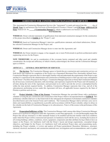
Product SpecificationsDimensional DataDUCT OPENING E41-1/4CONDENSERINLET20620ABVTC/VTH 09, 12, 186½6½VTC/VTH 2410203www.amana-ptac.comSS-VTAC
Product SpecificationsAccessories Wall-mounted Low-voltage ThermostatEasily controls the unit. Low-voltage wires exit the left side ofthe cabinet. (See Pg. 8.)Unit with Installed Rear Sleeve and FlushStyle Louver "Flush Style" Architectural LouverAttaches to the outside of the wall sleeve for a flush appearance.Louvers recess into the wall sleeve; stock and custom colors available. Wall SleevesStandard 22" width x 44" Height. Six sleeves (three rear installation, three side installation) available for varying wall widths,from 5" to 20". (See chart below and Figure 7, page 9.)Shipped separately to allow installation during construction,each sleeve includes a factory installed "weather guard" to coverthe sleeve opening during construction phase.Note: Sleeve, louver, filter, andthermostat required for eachgeneral installation.Note: Due to better access to unit, wall sleeves installed in the rear application are recommended over side-installed wall sleeves wheneverpossible.Side Wall SleevesModelWall DepthSleeve DepthSWS958A5" - 8" Walls26"SWS9812A8" - 12" Walls30"SWS91214A12" - 15" Walls33"20" WallsNote: Side-installed wall sleeves require different closet sizes and configurations. (See Page 10.)Rear Wall SleevesModelWall DepthSleeve DepthVWS95BA5" - 8" Walls26"VWS9812A8" - 12" Walls30"VWS91214A12" - 15" Walls33"20" WallsSeparate wall mounting bracketis shipped with "side install" wallsleeves.Architectural Grilles (Available in various colors)ModelWall DepthAGKV01CBAnodized Cluminum (Clear)AGKV01DBDark BrozeAGKV01TBStonewoodAGKV01WBWhiteAGKV015BCustom ColorSide Install SleeveSS-VTACwww.amana-ptac.com7
Product SpecificationsPRODUCT SPECIFICATIONSAccessories(cont.)A(.)CCESSORIES CONT Wall-mountedLow-voltage Thermostat* Optimal Access/Return Air Panelcontrols theLow-voltageunit. Low-voltagewires exit the left side of EasilyWall-mountedThermostat*the cabinet.Easily controls the unit. Low-voltage wires exit the left side of* Available for straight cool/hydronic chassis and heat pump chassis.the cabinet. UnitMountedFreezeSensor(UMF01A)* Availablefor straightcool/hydronic chassisand heat pump chassis.the unitwhen reducedflow or ice build-up are De-energizesUnit MountedFreezeSensorair(UMF01A)detected. Re-energizes the unit when normal operat ing condiDe-energizes the unit when reduced air ow or ice build-uptions resume.are detected. Re-energizes the unit when normal operating HydronicControl Module (HFC01A)*conditions Flowresume.theFlowamountof hot waterheat tothe unit. *Applies to RegulatesHydronicControlModule(HFC01A)*hydronic models only.Regulates the amount of hot water heat to the unit. *Applies tohydronic models only.Straight Cool/Digital cool - off -1246001 Access/Return Air Panel OptionalHydronic Chassisheat, auto - onPanels are availablein louveredDigitalor non-louveredand areHeatPumpcool - off In1246003sulated for isheat, auto - onpanel includes a 18” x 24” x 1” lter. Non-louvered panels requireexternal return air grilles and unit mount lters.Panels are available as louvered or non-louvered and are insulatStraight Cool/Digitalscrews.cool - offed to for sound reductionwith oonpanel includes an 18" x 24" x 1" filter. Non-louvered panels reHeat airPump- off quired external returngrilles and on Float Switch (FSE306A)*Opens the condensate pan automatically when water rises in theFloat(FSE306A)*pan Switchand shutsoff the system by breaking low or line voltageOpens yrisesin thecurrentcompressor.is esystembreakinglowpan,or linevoltagethefloatsideof thebyauxiliarydrainceilingwacurdamagerent to thecompressor.is normallyclosed.canByreplaceclippingis prevented.In Switchsome areas,this switchter oat switchthe sidethe n.damage is prevented. In some areas, this switch can replaceforan auxiliarybuildingcodesNote:The float drainswitch pan.must Localbe installedbeforeunitshouldis set in bethecheckedsleeve.*Appliesto hydronic models only.for application.Note: The oat switch must be installed before unit is set in the sleeve.*Applies to hydronic models only.Access / Return Air Panel ³ 4Access/Return Air PanelAccess/Return Air PanelDimensions (H x W)DescriptionAccess/ReturnAir Panel³ ⁴Louvered 1FrameOpening87 X 3184 X 28Non-Louvered 287 X 31Louvered 182 X 31Part #Description82 X 31Non-LouveredLouvered¹2931-11Part #ShipWt.LWP018740Dimensions(Hx W)84 X 28N/LWP0187Ship79X 28LWP0182 WeightFrameOpening79 xX 312887N/LWP018284x 285540Notes:931-12Non-Louvered²87 x 3184 x 28551 Includes 18 x 24 x 1 filter931-13Louvered¹82x3179x28552 Requires external return air grille and unit mount filter3 931-14Both panels Non-Louvered²are insulated for soundand82reductionx 3179 xhave28 tamper-proof55screws4Panels are shipped ten per cartonNote: A solid door or panel with aside wall return air grille will resultin lowersoundlevelsNote:A soliddoor or panel witha side wall return air grille willresult in lower sound levels.Part goodmanmfg.com“B”87.00Part #84.00AB8784SS-VTACSS-VTAC
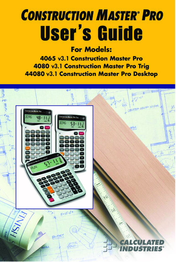
Product SpecificationsAccessories (cont.)FilterClipDuctedReturnAir ConnectionFresh Air VentFigure 5—Filter Bracket DetailOutdoor Air VentilationFigure 6One end of a 4” aluminum vent pipe is connected to thecondenser venturi and the other end is connected to theside of the VTC/VTH cabinet. A mesh screen is installedinside the vent pipe, and a metal plate on the side ofthe cabinet covers the opening of the vent pipe. Up to50 CFM of outside air is introduced into the equipmentcloset by removing the metal cover plate. The outsideair then mixes with the return air and is pulled throughthe evaporator coil and into the supply duct. The coverplate can be re-installed to partially close the outsideair opening if less than 50 CFM is desired. An externalsource of negative pressure (i.e., a bathroom fan) couldbe used to introduce more than 50 CFM of outside air.Consult with factory for further details.Note: It is suggested that a minimum 24” door be usedfor access. Closet interior may be smaller than listedhere as long as the door opening allows for removingthe unit. Door opening must line up with unit to allowremoval.Note: Sleeve protrudes ¼" (min.)through outside wall surfaceCloset WallFootprintOutside WallFootprintOutside Wall SurfaceCloset InsideWidth (min.)(VWS958A)(VWS9812A)Note:Bottom surface of sleeve pan to be located 6" (min.)above floor to facilitate drain installation. Please see WallSleeve Installation instruction book for complete instructions.(VWS91215A)Figure 7SS-VTACwww.amana-ptac.com9
Product SpecificationsGeneral AssemblyRough-In Dimensions44”H x 21 5/8”WApproximateFastener lterSleeve SealsRearAccess PanelWall SleeveDrain3/4” MPTElectrical ServiceKnock-out10www.amana-ptac.comOutsideSS-VTAC
Product SpecificationsInstallationRear InstallationNotes:Grillewidth: 22"1. Sleeve rough-in opening is 44” (H) x 21-5/8” (W)2. Bottom of opening should be approximately 6”above floor level.VTUnitUnit must line upwith door opening tofacilitate removal whennecessary.Min. 2"Req'd3. Minimum 3” clearance is required on all sides ofthe unit.Rear Installation—Closet DimensionsInstructions:To find the minimum closet depth (dimension “C”),use the following method:CADetermine dimension “A” which is the total finished wallthickness.27" (minimum)* For 5”-8” outside wall thickness, subtract “A: from 29” (C” 29 - “A”)* For 8”-12” outside wall thickness, subtract “A: from 33” (C” 33 - “A”)* For 12”-15” outside wall thickness, subtract “A” from 36”(C” 36 - “A”)Side Installation—Closet 2" min.12"min.SS-VTACATo find the minimum closet depth (dimension “C”), use thefollowing method:Determine dimension “A”, which is the total finished wallthickness.C30" min.27"min.min.Outside Wall30"min.* For 5”-8” outside wall thickness, subtract “A: from 39”(C” 39 - “A”)* For 8”-12” outside wall thickness, subtract “A: from 43” (C” 43 - “A”)* For 12”-15” outside wall thickness, subtract “A” from 46”(C” 46 - “A”)www.amana-ptac.com11
Product SpecificationsGuide SpecificationsRatings – Each unit must meet the following specifications:ARI rating of BTU/h cooling (andBTU/h reverse cycle heating with a COP of at 47 F O.D.)Electric resistance heat of BTU/h. Total Ampdraw must be of and Watts atvolts.The EER must be a minimum of EER.Unit Chassis — Each unit must be slide-out design, ready forinstallation into closet space. Unit must fit into closet spacenot to exceed 24” x 24” with overhead duct connectionsdesigned to .25 ESP. Unit must be tested for conformance toASTME water infiltration specification ASTME 331-86, whichensures no water infiltration when tested at 8" rain per hourat 63 mph wind for 15 min.Filter — Filter provided with the unit. Installer mustprovide for easy accessibility.Heat Pumps — Each unit must include a changeover thermostatthat senses an outside coil switch-over temperature of 25 F,lock-open refrigerant-reversing valve during heat pumpoperation, temperature-activated defrost drain and automat icemergency heat operation to over-ride the heat pump’schange-over thermostat and bring on electric resistanceheaters in the event of a sealed-system failure.Compressor — The compressor must be hermetically sealed,internally isolated, rotary-type and permanently mounted onrubber isolators. No removal or adjustment of compressorhold-down bolts is to be required during installation.Unit Controls — The unit must be controlled by a thermostat.Other unit controls must include a concealed ventilationcontrol to allow the introduction of filtered air into theroom, a concealed fan mode switch to allow the owner topreset for either continuous fan or thermostat ically cycledfan operation. Additionally, the following controls are to beincluded as standard on all units: Compressor restart delay Random restart circuit Front desk control Evaporator coil freeze protection Fan delay Low ambient lock-outEvaporator/Condenser Fans — Direct drive with a permanentsplit capacitor, two-speed motor. Must have a condenser fanand separate indoor evaporator motor. Condenser fan mustbe propeller type and evaporator fan must be blower type.Coils — Unit’s coils must have copper tubing expanded intorippled-edge louvered aluminum fins.Discharge and Return Air — A unit must be able to dischargeair through an overhead duct system with an external staticpressure capability of 0.35" for 9,000 and 12,000 unit sizesand 0.40" for 18,000 and 24,000 unit sizes. The return air mustbe capable of a free return at the unit or a ducted return.Warranty — Limited One-Year Warranty; Second- throughFifth-Year Limited Replacement Compressor Warranty. Fullwarranty details are available at www.amana-hac.com.Wall Sleeve — The wall sleeve must be of industry-accepteddimensions: from 21” [d] to 28” [d] (dependent upon wallwidth, from 5” to 15”) x 22” [w] x 44” [h] and constructed ofinsulated galvanized steel for corrosion resistance. Sleeve mustbe shipped with weather-resistant rear closure panel installed.Condensate Drain — The unit must have a condensate drainingsystem. A vertical pipe connection in the base pan is connectedto the evaporator drain pan via a drain line. Condensate passesfrom the unit to a catch tray, located in the wall sleeve, andexits the sleeve through a ¾” male NPT fitting. (This allowspiping to be done during construction stage).The unit must also have a secondary condensate drainingsystem for overflow. If the primary condensate draining systembecomes clogged, water will be directed from the catch tray,through the sleeve, to the outside of the building. Any externalwater source (rain, sleet, etc.) entering the sleeve will also bediverted to the building’s exterior.Outdoor Grilles — Must be architecturally extruded and madeof anodized aluminum (AGKV***A). All other grilles must besubmitted to our company for feasibility, airflow characteristicsand compliance with U.L. regulations, where necessary.Hydronic Heat Units — Required for heating functions insteadof electric resistance heaters. Unit must retain completeservice access with the kit installed. Proper water or steamvalves must be used; however, they are not included withthe Hydronic Heat Unit.Thermostats — A manual, auto-changeover or programmable thermostat must be installed to provide full remoteoperation of the chassis.Amana is a trademark of Maytag Corporation or its related companies and used under license to Goodman Company, L.P. All rights reserved. Our continuing commitment to quality products may mean a change in specifications without notice. 2010 Goodman Company, L.P. Houston, Texas Printed in the USA.12www.amana-ptac.comSS-VTAC
the cooling mode. Attached to the coil, a temperature sensor will de-energize the compressor when freezing conditions are detected and re-energize the compressor when the coil warms up again. table Return Air Duc Permits the connection of return air ductwork using the provid-ed tabs (usually not required) on the inlet of the evaporator coil.