Transcription
Multilin 350Intuitive and Innovative Feeder ProtectionThe Multilin 350 is a member of the Multilin 3 Series protective relay platform and has been designedfor the protection, control and management of feeders or related applications as a primary or backupprotection device. This cost-effective protective device is used to perform advanced feeder protection,control and monitoring in a draw-out or non draw-out design for low, medium and high voltageapplications. The 350 also offers enhanced features such as metering, monitoring and diagnostics,preventative maintenance, advanced communications and security.Key Benefits Cost-effective and flexible protection and control for distribution and industrial feeder applications Ease of use and setup in one simple step Environmental monitoring system to monitor operating conditions and plan preventive maintenanceProtection & Control Comprehensive overcurrent, voltage andfrequency functions Synchrocheck and breaker failure Wide variety of protection curves Thermal model protectionMetering & Monitoring Comprehensive metering Advanced power system diagnostics Event Recorder: 256 events with 1ms timestamping Flexible communications with multiple ports and protocols allowing seamless integration 32 samples per cycle oscillography Arc flash mitigation via zone inter-tripping, flex curves, and multiple settings group IRIG-B or IEEE 1588 time synchronization Powerful Security Audit Trail tool to increase security and minimize system risks Security audit trail and password control Application flexibility with the use of programmable logic elements Relay health diagnostics Effortless draw-out construction eliminates requirement for test switches Draw-out or non draw-out options available Increase network availability by reducing failover time to zero through IEC 62439-3 PRP and HSR support Provide precise time synchronization by support for IEEE 1588 (Precise Time Protocol (PTP)) Accelerated life cycle testing for high reliabilityApplications Primary protection and control for medium and high voltage distribution utility and industrialoverhead or cable feeder applications Protection of small and medium size distribution transformersCommunications Front USB and rear serial, Ethernet, Fiber anddual port options for seamless redundancy(IEC 62439-3, PRP & HSR) Multiple communication protocols includingIEC 61850, IEC 61850 GOOSE, Modbus TCP/ IP,Modbus RTU, DNP 3.0, IEC 60870-5-104,IEC 60870-5-103 & OPC-UA (IEC 62541) Back-up protection of various HV applicationsEnerVista Software Capacitor bank protection Simplify setup and configuration Advanced control applications including Cold Load Pickup, multi-shot recloser and multiple setting groups Strong document archive andmanagement system Full featured monitoring and data recording Maintenance and troubleshooting tool Seamless integration toolkit
350 Feeder Protection SystemOverviewEasy to UseAdvanced CommunicationsThe 350 relay is a member of the 3 Series familyof Multilin relays. This protective device is used toperform primary or back-up circuit protection onmedium or high voltage feeders and down streamprotection for distribution utilities. The 350 can beused for a wide variety of protection applicationsin power system such as MV/LV transfomerprotection and capacitor bank protection.Drawout ConstructionEasy Integration Into New or ExistingInfrastructureThe basic protection function of this relayincludes multiple phase, ground, and neutraltime and instantaneous overcurrent elementsfor coordination with upstream and downstreamdevices. Additionally, the device providesessential feeder breaker control features suchas cold load pick up blocking, breaker failure,synchrocheck and autoreclose.The robust 350 streamlines user work flowprocesses and simplifies engineering tasks suchas configuration, wiring, testing, commissioning,and maintenance. This cost-effective relay alsooffers enhanced features such as diagnostics,preventative maintenance, arc flash mitigationand security.The 350 offers a complete drawout featureeliminating the need for rewiring after testinghas been concluded. The withdrawable featurealso eliminates the need to open the switch geardoor and disconnect communication cables,eg. Ethernet fiber, copper, RJ45, etc prior toremoving the relay from the chasis.Effortless RetrofitThe small and compact 350 enables multiplerelays to be mounted side by side on mediumvoltage panels. It also allows easy retrofit intoexisting S1 and S2 cutouts with adapter plates.The 350 can be used with reducing collars whenthe depth of LV compartment is limited.Easy to ConfigureFast & Simple ConfigurationThe 350 requires minimal settings for configuringstandard feeder protection applications. Theentire feeder protection setup can be completedin one easy step.With several Ethernet and serial port options,and a variety of protocols, the 350 providesadvanced and flexible communication selectionsfor new and existing energy management ,SCADA, and DCS systems. The 350 also providesthe industry leading protocols such as PRP andHSR when any failover time in communicationsystem is not tolerated.Enhanced DiagnosticsPreventative MaintenanceThe 350 allows users to track relay exposure toextreme environmental conditions by monitoringand alarming at high ambient temperatures. Thisdata allows users to proactively schedule regularmaintenance work and schedule upgradeactivities. The diagnostics data enables the userto understand degradation of electronics due toextreme conditions.350 Relay Features2Easy to Configure- 1 Simple StepAdvanced & FlexibleCommunication OptionsEasy to Use - Draw-out CaseDiagnostic AlarmsGEDigitalEnergy.com
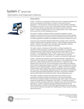
350 Feeder Protection SystemFunctional Block DiagramANSI Device Numbers & Functions BUSBUS VT5279CLOSETRIP59P159 0 2 51-211CLP50BF2149167P67NMETERINGTRANSIENT RECORDEREVENT RECORDER17950G/ 67G/SG50G/SG 51G/SG350 50N50G50BF50 251P51G51N67P59P59X59N59 267G67N7981U81OCLPVTFFFUNCTIONFunction SynchrocheckAuxiliary UndervoltageThermal ModelPhase Instantaneous OvercurrentNeutral Instantaneous OvercurrentGround/Sensitive Ground Instantaneous OvercurrentBreaker FailureNegative Sequence OvercurrentPhase Timed OvercurrentGround Timed OvercurrentNeutral Timed OvercurrentPhase Directional OvercurrentPhase OvervoltageAuxiliary OvervoltageNeutral OvervoltageNegative Sequence OvervoltageGround Directional OvercurrentNeutral Directional old Load PickupVoltage Transformer Fuse FailureLatched Lockout available as a standard featureCost EffectiveRobust DesignThe 350 is subjected to Accelerated Life Testing(ALT) to validate accurate relay function underspecified normal conditions. The device is furthertested for durability through Highly AcceleratedLife Testing (HALT) where it undergoes extremeoperating conditions. The robust 350 designensures long term operation.Reduced Life Cycle CostThe 350 is designed to reduce total installationand life cycle cost for feeder protection. Thedraw-out construction of the device reducesdowntime during maintenance and decreasesextra wiring needed for relay testing andcommissioning.Multiple time current curves are availableincluding IAC, IEC, ANSI and IEEE curves.Additional user programmable flex curvescan be used to customize and meet specificcoordination requirements. The TOC has bothlinear and instantaneous reset timing functionto coordinate with electro-mechanical relays.Instantaneous Overcurrent (Phase,Ground, Neutral)The instantaneous element provides fastclearance of high magnitude faults to preventdamage to the power infrastructure and theequipment connected to it.Neutral OvercurrentThe neutral signal is derived as the residual sumof the three phase CTs eliminating the need foran additional ground sensor.Sensitive Ground OvercurrentSensitive ground protection feature detects groundfaults on high impedance grounded systemsin order to limit damage to conductors andequipment. Special low ratio CT’s are used for thispurpose to detect low magnitude ground faults.Directional Overcurrent (Phase)This element is intended to send a directionalsignal to an overcurrent element to prevent anoperation when current is flowing in a particulardirection.The direction of current flow is determined bymeasuring the phase angle between the currentfrom the phase CTs and the line-line voltagefrom the other two phases. The MaximumTorque Angle (MTA) can be set from 0º to 359ºin steps of 1 .Multiple OptionsSeveral option for protection & communicationsare provided to match basic to high endapplication requirements.Logic DesignerProtectionThe 350 feeder protection system offersprotection, control and monitoring in oneintegrated, economical and compact package.Timed Overcurrent (Phase, Ground, Neutral)The 350 has three-phase TOC elements whichenable coordination with upstream anddownstream protection devices such as fuses,overload relays, etc to maximize fault selectivityand minimize interruptions and downtime.Sixteen logic elements available for applications such as manual control, interlocking, and peer topeer tripping.GEDigitalEnergy.com3
350 Feeder Protection SystemGround DirectionalThe Ground Directional element is used todiscriminate whether a fault occurs in a forwardor in a reverse direction, and it can be usedeither individually or as a part of the GroundTime, or Instantaneous over-current elements.Neutral DirectionalThe Neutral Directional element is used todiscriminate between faults that occur in theforward direction, and faults that occur inthe reverse direction. The Neutral Directionalelement can be used either individually forcontrol or alarm by energizing the auxiliaryoutput relays, or as a part of the Neutral Time, orInstantaneous, over-current elements to definethe tripping direction.Over/Under Voltage ProtectionOvervoltage/Undervoltage protection featurescan cause a trip or generate an alarm when thevoltage exceeds a specified voltage setting for aspecified time.Frequency ProtectionThe 350 offers overfrequency and underfrequencyelements to improve network (grid) stabilityusing voltage or frequency based load sheddingtechniques.It also provides back up protection whenprotecting feeders and other frequency sensitivepower equipment.Thermal ModelThe cable thermal model element protectspower apparatus like feeder cables againstoverheating due to excessive load. It estimatesthe temperature rise of current carryingconductors based on the amount of current flow(I2R) and alarms when temperature rise exceedsa threshold value. This protection feature isessential to ensure the longevity of electricalfeeders; particularly important to preventpremature cable failures, expensive repair costsand system down time.Neutral/Ground Directional OvercurrentThe directional ground overcurrent isolatesfaulted feeders in ring bus or parallel feederarrangements. It also allows detection of backfeed of fault current from feeders with motors.ControlSynchronism CheckThe Synchrocheck element is used formonitoring the connection of two parts of thecircuit by the close of a breaker. Breaker closingcan be supervised by ΔV, Δf and ΔHz setpoints.This element verifies that voltages at both sidesof the breaker are within the magnitude, angleand frequency limits set by the user beforeclosing the breaker, in order to minimize internaldamage that could occur due to the voltagedifference, both in magnitude and angle.Cold Load Pick UpCold Load Pick up allows automatic or manualblocking or raising of trip settings for a periodafter the breaker has been closed. This featureadapts the pick up of overcurrent elements tooverride the higher overload currents resultingfrom re-energization of feeder after a longperiod of time.Power System TroubleshootingAnalyze power system disturbances with transient fault recorder and event records4GEDigitalEnergy.comBreaker FailureThe Breaker Failure function is used to determinewhen a trip command sent to a breaker has notbeen executed within a selectable time delay.In the event of a breaker failure, the 350 willissue an additional signal to trip the breakersconnected to the same busbar or signal the tripof upstream breakers.AutorecloseReclose can be initiated externally or froman overcurrent protection. Up to four recloseoperations are available, each with aprogrammable dead time. For each recloseshot, the relay can be programmed to block anyovercurrent element.Automation and IntegrationInputs & OutputsThe 350 features the following inputs andoutputs for monitoring and control of typicalfeeder applications: 10 contact Inputs with programmablethresholds 2 Form A output relays for breaker trip andclose with coil monitoring 5 Form C output relaysIEC 61850 GOOSEThe 350 supports IEC 61850 Logical Nodeswhich allows for digital communications toDCS, SCADA and higher level control systems.In addition, the 350 also supports IEC 61850GOOSE communication, providing a means ofsharing digital point state information between350’s or other IEC 61850 compliant IED’s.
350 Feeder Protection System Eliminates the need for hardwiring contactinputs to contact outputs via communicationmessaging. Transmits information from one relay to thenext in as fast as 8 ms. Enables sequence coordination withupstream and downstream devices. When Breaker Open operation malfunctions,GOOSE messaging sends a signal to theupstream breaker to trip and clear the fault.events, and includes the metered values at themoment of the event.Oscillography/ Transient Fault RecorderThe 350 captures current and voltagewaveforms and digital channels at 32 samplesper cycle. Multiple records can be stored in therelay at any given time with a maximum lengthof 192 cycles Oscillography is triggered either byinternal signals or an external contact.Logic ElementsTrip/Close Coil MonitoringThe 350 relay has sixteen Logic Elementsavailable for the user to build simple logicusing the state of any programmed contact,virtual, remote input or the output operand of aprotection or control element.The 350 can be used to monitor the integrityof both the breaker trip and closing coils andcircuits. The supervision inputs monitor both thebattery voltage level, while the outputs monitorthe continuity of the trip and/or closing circuits,by applying a small current through the circuits.The logic provides for assigning up to threetriggering inputs in an “AND/OR” gate for thelogic element operation and up to three blockinginputs in an “AND/OR” gate for defining the blocksignal. Pickup and dropout timers are availablefor delaying the logic element operation andreset respectively.Virtual InputsVirtual inputs allow communication devicesthe ability to write digital commands to the 350relay. These commands could be open/close thebreaker, changing setting groups, or blockingprotection elements.Multiple Settings GroupTwo separate settings groups are stored innonvolatile memory, with only one group activeat a given time. Switching between settinggroups 1 and 2 can be done by means of asetting, a communication command or contactinput activation.Basic MeteringMetered values include: Current: Ia, Ib, Ic, In, Ig, Isg Phase-to-phase and phase-to-groundvoltages for bus and line: Van, Vbn, Vcn, Vab,Vbc, Vca Active power (3-Phase) Reactive power (3-Phase) FrequencyAdvanced Device Health DiagnosticsThe 350 performs comprehensive device healthdiagnostic tests during startup and continuouslyat runtime to test its own major functionsand critical hardware. These diagnostic testsmonitor for conditions that could impact systemreliability. Device status is communicated viaSCADA communications and the front paneldisplay. This continuous monitoring and earlydetection of possible issues helps improvesystem availability by employing predictivemaintenance.IEEE 1588 (Precise Time Protocol)The IEEE 1588 Precision Time Protocol (PTP) is tosynchronize the time between different nodeson an Ethernet network and it is used when veryprecise time synchronization is required.It is possible to synchronize distributed clockswith an accuracy of less than 1 microsecondvia Ethernet networks. PTP enables clockredundancy and reduces wiring and testing. Itcan operate over a complete facility and has theability to compensate for lead length.IRIG-BIRIG-B is a standard time code format that allowstime stamping of events to be synchronizedamong connected devices within 1 millisecond.An IRIG-B input is provided in the 350 to allowtime synchronization using a GPS clock overa wide area. The 350 IRIG-B supports bothAM and DC time synchronization with an autodetect feature that removes the requirement formanual selection.Temperature MonitoringThe 350 continually monitors ambienttemperature around the relay and alarms whenthe device is exposed to extreme temperaturesand undesirable conditions such as airconditioning unit or station heater failures.The EnerVista Viewpoint maintenance toolallows users to review and analyze the timeperiod a 350 relay is exposed to certaintemperature ranges.The two settings groups allow users to storeseasonal settings – such as for summer andwinter or alternate profiles such as settingsduring maintenance operations.Monitoring & DiagnosticsEvent RecordingEvents consist of a broad range of change ofstate occurrences, including pickups, trips,contact operations, alarms and self test status.The 350 relay stores up to 256 events timetagged to the nearest millisecond. This providesthe information required to determine sequenceof events which facilitates diagnosis of relayoperation. Event types are individually maskablein order to avoid the generation of undesiredTrace any settingchanges with securityaudit trailGEDigitalEnergy.com5
350 Feeder Protection SystemExample of Redundant HSR and PRP ArchitectureSCADALocal HMI /Single torianstandard that defines two protocols to increasenetwork availability by reducing failover timeto zero. Both ports are capable of simultaneouslysupporting the following protocols: Modbus TCP/IP, IEC 61850, DNP3 or IEC 60870-5-104, IEEE 1588,SNTP and OPC-UA.The basic concept of both protocols, PRP and HSR,is to send identical frames over different pathsand discard one of the copies in reception, atbest. If an error occurs or one of the paths goesdown, the frame travelling through that path willnot reach its destination, but its copy remainsintact and will reach the desired destination. Thistechnology ensures high reliability and availabilityof communication networks by providingredundancy and zero reconfiguration time in theevent of a failure. Failsafe communications systemsare crucial for industries and utilities with criticalapplications where no recovery time is tolerated.D400The 350 supports popular industry leadingstandard protocols enabling easy, directintegration into electrical SCADA and HMI systems.The protocols supported by the 350 include:8 SeriesF650350PRP NetworkURF650350HSR Ring IEC 61850 IEC 60870-5-104 IEC 61850 GOOSE DNP 3.0 PRP & HSR(IEC 62439-3) Modbus RTU OPC-UA Modbus TCP/IP IEEE 1588 for timesynchronizationRedundancy protocols (PRP and HSR) can be used for various networking architectures includingcombined PRP/HSR topologies. IEC 60870-5-103SecurityThe 350 relay provides Precision Time Protocol(PTP) based on IEEE 1588 for precise timesynchronization throughout a network. OPC-UAis another feature based on IEC 62541 that the350 relay offers.Security Audit TrailThe Security Audit Trail feature providescomplete traceability of relay setting changesat any given time and is NERC CIP compliant.The 350 maintains a history of the last 10changes made to the 350 configuration,including modifications to settings and firmwareupgrades.Security Setting Reports include the followinginformation: If Password was required to change settings MAC address of user making setting changes Listing of modified changes Method of setting changes - Keypad, Frontserial port, Ethernet, etc.Password ControlWith the implementation of the PasswordSecurity feature in the 350 relay, extra measureshave been taken to ensure unauthorizedchanges are not made to the relay. When6password security is enabled, changing ofsetpoints or issuing of commands will requirepasswords to be entered. Separate passwordsare supported for remote and local operators,and separate access levels support changing ofsetpoints or sending commands.Advanced CommunicationsThe 350 incorporates the latest communicationtechnologies making it the easiest and themost flexible feeder protection relay for use andintegration into new and existing infrastructures.The 350 relay provides the user with one front USBand one rear RS485 communication port. Alsoavailable with the 350 is a rear communicationport with Ethernet Fiber and Copper. In caseof implementing PRP and HSR redundancyprotocols, the 350 provides two rear Fiber ports.Through the use of these ports, continuousmonitoring and control from a remote computer,SCADA system or PLC is possible.The 350 provides optional Parallel RedundancyProtocol (PRP) and High Availability SeamlessRing (HSR) according to the IEC 62439-3GEDigitalEnergy.comThese protocols make it easy to connect toa Utility or Industrial automation system,eliminating the need for external protocolconverter devices.EnerVista SoftwareThe EnerVista suite is an industry leading setof software programs that simplifies everyaspect of using the 350 relay. The EnerVistasuite provides all the tools to monitor the statusof the protected asset, maintain the relay, andintegrate the information measured into DCSor SCADA monitoring systems. ConvenientCOMTRADE and sequence of event viewers arean integral part of the 350 set up software andare included to ensure proper protection andsystem operation.Simplified Feeder SetupThe 350 Feeder Protection System includes asimplified setup process. This simplified feeder
350 Feeder Protection Systemsetup consists of minimal settings and canbe accessed through the relay front panel orvia the EnerVista Setup software. Once theinformation is entered, the simplified setup willgenerate a settings file, provide documentationindicating which settings are enabled, and anexplanation of the parameters entered.LEDsThe 350 relay has twelve* LED’s (8 programmable) that provide status indication for various conditions ofthe relay and the system. The LED indications are color coded to indicate the type of event.* 10 non programmable LEDs for the non draw-out designUser InterfaceSETPOINT GROUP 1, 2:Trip, Alarm and Pick Up indicators arecontinuously on for protection elements.Viewpoint MonitoringViewpoint Monitoring is a simple to use andfull featured monitoring and data recordingsoftware package for small systems. Viewpointmonitoring provides a complete HMI packagewith the following functionality:DISPLAY:4 line text for easy viewing of key data Plug and play device monitoring System single line monitoring and control Annunciator alarm screensLEDs:10/12 LED indicators for quick diagnostics Trending reports Automatic event retrieval Automatic waveform retrievalKEYPAD:Ten button keypad for access to deviceinterrogation and change of settings.DisplayFRONT PORT:Electrically isolated front USBcommunication portA 4 line liquid crystal display (LCD) allowsvisibility under varied lighting conditions. Whenthe keypad and display are not being used, themetering summary page is displayed to showcritical metered values.USER INTERFACE OPTIONS:Draw-out and non draw-out optionsavailableFeeder protection settings in one easy stepFast and accurate configuration in one simple screen.3 Series setup software protection summary for viewing a summary ofProtection & Control configuration.GEDigitalEnergy.com7
350 Feeder Protection SystemDimensionsDraw-out versionNon draw-out version3.96”[100.6mm]10 ounting3 Series Depth Reducing Collar5.350” 0.010”(131.1 mm 0.25mm)4.100” 0.010”(104.1 mm 0.25 mm)LCΦ 0.200”(5.1 mm)6.900” 0.010”(175.3 mm 0.25 mm)LC6.000” 0.010”(152.4 mm 0.25 mm)4.000” 0.010”(101.6 mm 0.25 mm)(in)8GEDigitalEnergy.com
350 Feeder Protection SystemTypical Wiring Diagram - Draw-outDIRECTION OF POWER FLOW FOR POSITIVE WATTSPOSITIVE DIRECTION OF LAGGING VARsA B CFEEDER CtsBUS VtsFEEDER1A OR 5A52WYE VTCONNECTIONCONNECT AUX VTAS REQUIRED CONTROL- POWERE5 D5 E6 D6 E7 D7 E8 D8IAIAIBICIBICIGIGE9 D9 E10D10E11D11E12D12B1 A1B2VA V A V B V B V C V C V X V X -chassisgndPOWER SUPPLYVOLTAGE INPUTSCURRENT INPUTSGROUNDBUSBreaker Aux Contacts52bA2GE MultilinC1 52a (C1 #1)C2 52b (C1 #2)C3 INPUT 3C4 INPUT 4C5 INPUT 5C6 INPUT 6C7 INPUT 7C8 INPUT 8C9 INPUT 9C10 INPUT 10C11 COMMON350Feeder Protection SystemVA3A4VB5A53 AUXILIARYB6A64 AUXILIARYA75 AUXILIARY6 AUXILIARYUSBB9A9B10A10B114 WIRE ETHERNET10/100 BASE-T100 J CLOSECOILTRIPCIRCUITA8TYPE BRear Pane l B7Front Panel4 WIRE USB52aTRIPCOILB42 CLOSEC12 CHASSIS GNDPERSONALCOMPUTERB31 TRIPDIGITAL INPUTS52aCOMMUNICATIONSIRIG-B- RS485COM- 7 CRITICALFAILURERELAYA11OUTPUT CONTACTSSHOWN WITH NOCONTROL POWERB12A12OPEN DELTA VT CONNECTIONF2 F1 F5 F4 F3GROUNDBUSSEE COMMUNICATIONS WIRINGIN INSTRUCTION MANUALCOME9 D9 E10D10 E11 D11RS485898728.CDRGEDigitalEnergy.com9
350 Feeder Protection SystemTechnical SpecificationsPHASE/NEUTRAL/GROUND TIME OVERCURRENT(51P/51N/51G)Pickup Level:0.05 to 20.00 x CT in steps of 0.01 x CTDropout Level:97 to 99% of Pickup @ I 1 x CTPickup - 0.02 x CT @ I 1 x CTCurve Shape:ANSI Extremely/Very/Moderately/Normally InverseDefinite Time (0.05 s base curve)IEC Curve A/B/C/ShortIAC Extreme/Very/Inverse/ShortUser Curve, FlexCurve A/B(programmable curves)Curve Multiplier:0.05 to 50.00 in steps of 0.01Reset Time:Instantaneous, LinearTime Delay 3% of expected inverse time or 1 cycle,Accuracy:whichever is greaterLevel Accuracy:per CT inputSENSITIVE GROUND TIME OVERCURRENT (51SG)Pickup Level:0.005 to 3 x CT in steps of 0.001 x CTDropout Level:97 to 99% of Pickup @ I 0.1 x CTPickup - 0.002 x CT @ I 0.1 x CTCurve Shape:ANSI Extremely/Very/Moderately/Normally InverseDefiniteTimeIEC Curve A/B/C/Short InverseIAC Extreme/Very/Inverse/Short InverseUser Curve, FlexCurve A/BCurve Multiplier:0.05 to 50.00 in steps of 0.01Reset Time:Instantaneous, LinearTime Delay 3% of expected inverse time or 1 cycle,Accuracy:whichever is greaterLevel Accuracy:per CT inputPHASE/NEUTRAL/GROUND NEGATIVE SEQUENCEINSTANTANEOUS OVERCURRENT (50P/50N/50G/50 2)Pickup Level:0.05 to 20 x CT in steps of 0.01 x CTDropout Level:97 to 99% of Pickup @ I 1 x CTPickup - 0.02 x CT @ I 1 x CTTime delay:0.00 to 300.00 sec in steps of 0.01Operate Time: 30 ms @ 60Hz (I 2.0 x PKP, No timedelay) 35 ms @ 50Hz (I 2.0 x PKP, No timedelay)Time Delay0 to 1 cycle (Time Delay selected)Accuracy:Level Accuracy:per CT inputSENSITIVE GROUND INSTANTANEOUS OVERCURRENT (50SG)Pickup Level:0.005 to 3 x CT in steps of 0.001 x CTDropout Level:97 to 99% of Pickup @ I 0.1 x CTPickup - 0.002 x CT @ I 0.1 x CTTime delay:0.00 to 300.00 sec in steps of 0.01Operate Time: 30 ms @ 60Hz (I 2.0 x PKP, No timedelay) 35 ms @ 50Hz (I 2.0 x PKP, No timedelay)Time Delay0 to 1 cycle (Time Delay selected)Accuracy:Level Accuracy:per CT inputPHASE DIRECTIONAL (67P)Directionality:Co-existing forward and reverseOperating:Phase Current (Ia, Ib, Ic)Polarizing Voltage: Quadrature Voltage(ABC phase sequence: Vbc, Vca, Vab)(CBA phase sequence: Vcb, Vac, Vba)Polarizing Voltage 0.05 to 1.25 x VT in steps of 0.01ThresholdMTAFrom 0º to 359º in steps of 1 Angle Accuracy: 4ºOperation Delay:20 to 30 msGROUND DIRECTIONAL (67G)Directionality:Co-existing forward and reverseOperating:Ground Current (Ig)Polarizing Voltage: V calculated using phase voltages (VTsmust be connectedin “Wye”)- 3V measured from Vaux input . (3Vprovided by an externalopen delta connection).MTA:From 0 to 359 in steps of 1 Angle Accuracy: 4ºOperation Delay:20 to 30 ms00METERING SPECIFICATIONSParameter3-Phase Real Power (MW)3-Phase Reactive Power (Mvar)3-Phase Apparent Power (MVA)Power FactorFrequency10NEUTRAL DIRECTIONAL (67N)Directionality:Co-existing forward and reversePolarizing:Voltage, Current, DualPolarizing Voltage: V calculated using phase voltages (VTsmust beconnected in “Wye”)- 3V measured by Vaux input (3Vprovided by an externalopen delta connection).Polarizing Current: IgMTA:From 0 to 359 in steps of 1 Angle Accuracy: 4ºOperation Delay:20 to 30 ms000PHASE/AUXILIARY UNDERVOLTAGE (27P/27X)Minimum Voltage:Programmable from 0.00 to 1.25 x VTin steps of 0.01Pickup Level:0.00 to 1.25 x VT in steps of 0.01Dropout Level:101 to 104% of pickupCurve:Definite Time, Inverse TimeTime Delay:0.0 to 600.0 s in steps of 0.1Operate Time:Time delay 30 ms @ 60Hz (V 0.85 xPKP)Time delay 40 ms @ 50Hz (V 0.85 xPKP)Time Delay 3% of expected inverse time or 1Accuracy:cycle, whichever is greaterLevel Accuracy:Per voltage inputPHASE/AUXILIARY/NEUTRAL/NEG SEQ OVERVOLTAGE(59P/59X/59N/59 2)Minimum Voltage: Programmable from 0.00 to 1.25 x VT insteps of 0.01Pickup Level:0.00 to 1.25 x VT in steps of 0.01Dropout Level:96 to 99% of pickupTime Delay:0.0 to 600.0 s in steps of 0.1Operate Time:Time delay 35 ms @ 60Hz (V 1.1 x PKP)Time delay 40 ms @ 50Hz (V 1.1 x PKP)Time Delay0 to 1 cycle (Time Delay selected)Accuracy:Level Accuracy:Per voltage inputUNDERFREQUENCY (81U)Minimum Voltage:0.00 to 1.25 x VT in steps of 0.01Pickup Level:40.00 to 70.00 Hz in steps of 0.01Dropout Level:Pickup 0.03 HzTime Delay:0.0 to 600.0 s in steps of 0.1Time Delay0 to 6 cycles (Time Delay selected)Accuracy:Operate Time:Typically 10 cycles @ 0.1Hz/s changeLevel Accuracy: 0.01 HzOVERFREQUENCY (81O)Pickup Level:40.00 to 70.00 Hz in steps of 0.01Dropout Level:Pickup -0.03 HzTime Delay:0
The Multilin 350 is a member of the Multilin 3 Series protective relay platform and has been designed for the protection, control and management of feeders or related applications as a primary or backup . Sixteen logic elements available for applications such as manual control, interlocking, and peer to peer tripping. Logic Designer. 350 .