Transcription
HP ProLiant ML310e Gen8 v2 ServerUser GuideAbstractThis document is for the person who installs, administers, and troubleshoots servers and storage systems. HP assumes you are qualified in theservicing of computer equipment and trained in recognizing hazards in products with hazardous energy levels.Part Number: 719821-001aApril 2014Edition: 1
Copyright 2013, 2014 Hewlett-Packard Development Company, L.P.The information contained herein is subject to change without notice. The only warranties for HP products and services are set forth in the expresswarranty statements accompanying such products and services. Nothing herein should be construed as constituting an additional warranty. HP shallnot be liable for technical or editorial errors or omissions contained herein.Microsoft and Windows are U.S. registered trademarks of Microsoft Corporation.
ContentsComponent identification . 6Front panel components . 6Front panel LEDs and buttons . 7Rear panel components . 8Rear panel LEDs and buttons . 9System board components . 10DIMM slot locations . 11PCIe expansion slot definitions . 11System maintenance switch . 11NMI functionality . 12Drive numbering . 12Hot-plug drive LED definitions . 13FBWC module LED definitions . 14Fan locations . 15Operations. 16Power up the server . 16Power down the server . 16Unlock the tower bezel . 17Remove the tower bezel . 17Install the tower bezel . 17Remove the access panel . 18Install the access panel . 19Remove the air baffle . 19Install the air baffle . 20Setup. 22Optional installation services . 22Rack planning resources . 22Optimum environment. 22Space and airflow requirements . 23Temperature requirements . 23Power requirements . 23Electrical grounding requirements . 23Server warnings and cautions. 24Rack warnings . 24Identifying the contents of the server shipping carton. 25Installing hardware options . 25Installing the server into the rack . 25Installing the operating system . 26Powering on and selecting boot options . 27Registering the server. 27Hardware options installation. 28Introduction . 28Drive options . 28Drive installation guidelines . 28Contents3
Installing a non-hot-plug drive . 28Installing a hot-plug drive . 30Drive cage options . 31Four-bay LFF hot-plug drive backplane option . 31Eight-bay SFF hot-plug drive cage option . 34Controller options . 36Installing a storage controller . 36Installing the FBWC module and capacitor pack . 37Optical drive option . 39Memory options . 41HP SmartMemory . 42DIMM identification . 42Single-rank and dual-rank DIMMs . 43Memory subsystem architecture . 43ECC memory . 43General DIMM slot population guidelines . 44Installing a DIMM. 44Expansion board options . 45HP Trusted Platform Module option . 49Installing the Trusted Platform Module board . 49Retaining the recovery key/password. 51Enabling the Trusted Platform Module . 51RPS enablement option . 51Setting up the HP PS1810-24G Switch (optional) . 55Cabling . 59Cabling overview . 59System fan cabling . 59Storage cabling . 60Four-bay LFF drive cabling . 60Eight-bay SFF drive cabling . 62Optical drive cabling. 62Power supply cabling . 64Integrated power supply cabling . 64Redundant power supply cabling . 64Capacitor pack cabling . 65Software and configuration utilities . 66Server mode . 66HP product QuickSpecs . 66HP iLO Management Engine . 66HP iLO . 66Intelligent Provisioning . 68Erase Utility . 69HP Insight Remote Support software . 70Scripting Toolkit . 70HP Service Pack for ProLiant . 70HP Smart Update Manager . 71HP ROM-Based Setup Utility . 71Using RBSU . 72Auto-configuration process . 72Boot options . 73Re-entering the server serial number and product ID . 73Utilities and features . 73Contents4
Array Configuration Utility . 73Option ROM Configuration for Arrays. 74ROMPaq utility. 75Automatic Server Recovery . 75USB support . 75Redundant ROM support . 76Keeping the system current . 76Drivers . 76Software and firmware . 76Version control . 76HP operating systems and virtualization software support for ProLiant servers . 77HP Technology Service Portfolio . 77Change control and proactive notification . 77Troubleshooting . 78Troubleshooting resources . 78System battery replacement. 79Regulatory information . 81Safety and regulatory compliance . 81Turkey RoHS material content declaration . 81Ukraine RoHS material content declaration . 81Warranty information . 81Electrostatic discharge . 82Preventing electrostatic discharge . 82Grounding methods to prevent electrostatic discharge . 82Specifications . 83Environmental specifications . 83Server specifications . 83Power supply specifications . 83HP 350 W 4U Integrated Power Supply . 84HP 460 W CS Gold Hot-plug Power Supply (92% efficiency) . 84Hot-plug power supply calculations . 85Support and other resources . 86Before you contact HP . 86HP contact information . 86Customer Self Repair . 86Acronyms and abbreviations . 94Documentation feedback . 98Index . 99Contents5
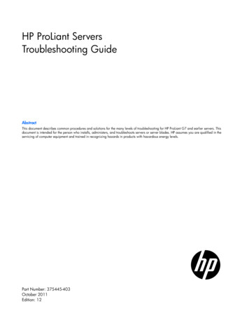
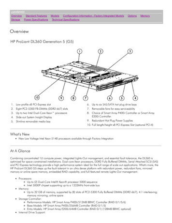
Component identificationFront panel componentsItemDescription1Optical drive (optional)2Media drive bay3Power On/Standby button and system power LED4USB connectors5Drive bays (inside)Component identification6
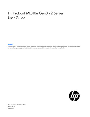
Front panel LEDs and buttonsItemDescriptionStatus1UID button/LEDSolid blue ActivatedFlashing blue (1 Hz/cycle per sec) Remote management orfirmware upgrade in progressOff Deactivated2Health LEDSolid green NormalFlashing amber System degradedFlashing red (1 Hz/cycle per sec) System criticalFast-flashing red (4 Hz/cycles per sec) Power fault*3NIC status LEDSolid green Link to networkFlashing green (1 Hz/cycle per sec) Network activeOff No network activity4Power On/Standby buttonand system power LEDSolid green System onFlashing green (1 Hz/cycle per sec) Performing power on sequenceSolid amber System in standbyOff No power present***To identify components in a degraded or critical state, see the Systems Insight Display LEDs, check iLO/BIOS logs, andreference the server troubleshooting guide.**Facility power is not present, power cord is not attached, no power supplies are installed, power supply failure hasoccurred, or the power button cable is disconnected.Component identification7
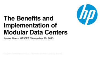
Rear panel componentsItemDescription1Power supply2Kensington security slot3Slot 4 PCIe x16 (8, 4, 1)*4Slot 3 PCIe x8 (8, 4, 1)*5Slot 2 PCIe x8 (1)*6Slot 1 PCIe x4 (1)*7Serial connector8Video connector9Dedicated iLO port10USB 3.0 connectors11UID LED/button12NIC connectors* For more information on the expansion slot specifications, see "PCIe expansion slot definitions."Component identification8
Rear panel LEDs and buttonsItemDescriptionStatus1UID button/LEDSolid blue ActivatedFlashing blue (1 Hz/cycle per sec) Remote management or firmwareupgrade in progressOff Deactivated2NIC status LEDSolid Green Activity existsFlashing green Activity existsOff No activity exists3NIC link LEDSolid green Link existsOff No link existsComponent identification9
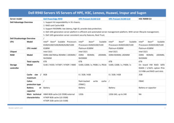
System board componentsItemDescription1RPS connector2Processor socket3TPM connector4System battery524-pin power supply connector6Mini-SAS connector7SATA connectors8Internal USB cable connector9Internal USB connector10Micro SD card slot11Front USB connector 212Front USB connector 113Front panel connector14Front system fan connector (fan 2)15Ambient thermal sensor connector16NMI header17System maintenance switch18Slot 1 PCIe2 x4 (1)*19Slot 2 PCIe2 x8 (1)*20Slot 3 PCIe3 x8 (8, 4, 1)*21Slot 4 PCIe3 x16 (8, 4, 1)*22Rear system fan connector (fan 1)234-pin power supply connector24DIMM slotsComponent identification10
* For more information on the expansion slot specifications, see "PCIe expansion slot definitions."DIMM slot locationsDIMM slots are numbered 1 through 4. Letters are used for AMP mode DIMM ordering.PCIe expansion slot definitionsSlot numberTypeLengthHeightConnector link widthNegotiable link lFullx8x84PCIe3FullFullx16x8System maintenance switchSwitchDefaultFunction1OffOff No functionOn iLO security is disabled2OffOff System configuration can bechangedOn System configuration is locked5OffOff Power-on password is enabledOn Power-on password is disabled6OffOff No functionOn ROM reads configuration asinvalid3, 4, 7, 8, 9,10, 11, 12—ReservedWhen the system maintenance switch position 6 is set to the On position, the system is prepared to erase allsystem configuration settings from both CMOS and NVRAM.Component identification11
CAUTION: Clearing CMOS and/or NVRAM deletes configuration information. Be sure toproperly configure the server or data loss could occur.NMI functionalityAn NMI crash dump creates a crash dump log before resetting a system which is not responding.Crash dump log analysis is an essential part of diagnosing reliability problems, such as failures of operatingsystems, device drivers, and applications. Many crashes freeze a system, and the only available action foradministrators is to restart the system. Resetting the system erases any information which could supportproblem analysis, but the NMI feature preserves that information by performing a memory dump before asystem reset.To force the system to invoke the NMI handler and generate a crash dump log, do one of the following: Use the iLO Virtual NMI feature. Short the NMI header.For more information, see the HP SupportManual/c00797875/c00797875.pdf).Drive numbering Four-bay LFF drive modelComponent identification12
Eight-bay SFF drive modelHot-plug drive LED definitionsItemLEDStatusDefinition1LocateSolid blueThe drive is being identified by a host application.Flashing blueThe drive carrier firmware is being updated or requires an update.Rotating greenDrive activityOffNo drive activitySolid whiteDo not remove the drive. Removing the drive causes one or more ofthe logical drives to fail.OffRemoving the drive does not cause a logical drive to fail.Solid greenThe drive is a member of one or more logical drives.Flashing greenThe drive is rebuilding or performing a RAID migration, stripe sizemigration, capacity expansion, or logical drive extension, or iserasing.Flashingamber/greenThe drive is a member of one or more logical drives and the systempredicts the drive will fail.Flashing amberThe drive is not configured and the system predicts the drive willfail.234Activity ringDo not removeDrive statusComponent identification13
ItemLEDStatusDefinitionSolid amberThe drive has failed.OffThe drive is not configured by a RAID controller.FBWC module LED definitionsThe FBWC module has three single-color LEDs (one amber and two green). The LEDs are duplicated on thereverse side of the cache module to facilitate status viewing.1 - Amber2 - Green3 - GreenInterpretationOffOffOffThe cache module is not powered.OffFlashing 0.5 HzFlashing 0.5 HzThe cache microcontroller is executing from within itsboot loader and receiving new flash code from the hostcontroller.OffFlashing 1 HzFlashing 1 HzThe cache module is powering up, and the capacitorpack is charging.OffOffFlashing 1 HzThe cache module is idle, and the capacitor pack ischarging.OffOffOnThe cache module is idle, and the capacitor pack ischarged.OffOnOnThe cache module is idle, the capacitor pack is charged,and the cache contains data that has not yet beenwritten to the drives.OffFlashing 1 HzOffA backup is in progress.OffOnOffThe current backup is complete with no errors.Flashing 1 HzFlashing 1 HzOffThe current backup failed, and data has been lost.Flashing 1 HzFlashing 1 HzOnA power error occurred during the previous or currentboot. Data may be corrupt.Flashing 1 HzOnOffAn overtemperature condition exists.Flashing 2 HzFlashing 2 HzOffThe capacitor pack is not attached.Flashing 2 HzFlashing 2 HzOnThe capacitor has been charging for 10 minutes, buthas not reached sufficient charge to perform a fullbackup.OnOnOffThe current backup is complete, but power fluctuationsoccurred during the backup.Component identification14
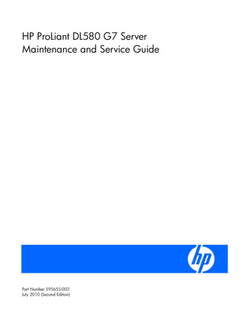
1 - Amber2 - Green3 - GreenInterpretationOnOnOnThe cache module microcontroller has failed.Fan locationsItemDescription1Rear system fan (fan 1, for processor cooling)2Front system fan (fan 2, for expansion board cooling)Component identification15
OperationsPower up the server1.Connect each power cord to the server.2.Connect each power cord to the power source.3.Press the Power On/Standby button.The server exits standby mode and applies full power to the system. The system power LED changesfrom amber to green.Power down the serverBefore powering down the server for any upgrade or maintenance procedures, perform a backup of criticalserver data and programs.WARNING: To reduce the risk of personal injury, electric shock, or damage to the equipment,remove the power cord to remove power from the server. The front panel Power On/Standbybutton does not completely shut off system power. Portions of the power supply and some internalcircuitry remain active until AC power is removed.IMPORTANT: When the server is in standby mode, auxiliary power is still being provided to thesystem.To power down the server, use one of the following methods: Press and release the Power On/Standby button.This method initiates a controlled shutdown of applications and the OS before the server enters standbymode. Press and hold the Power On/Standby button for more than 4 seconds to force the server to enterstandby mode.This method forces the server to enter standby mode without properly exiting applications and the OS.If an application stops responding, you can use this method to force a shutdown. Use a virtual power button selection through iLO.This method initiates a controlled remote shutdown of applications and the OS before the server entersstandby mode.Before proceeding, verify the server is in standby mode by observing that the system power LED is amber.Operations16
Unlock the tower bezelThe tower bezel must be unlocked and opened to access the drive cage and media bays. It must be unlockedto remove the access panel. The bezel must remain closed during normal server operations.Remove the tower bezel1.Unlock the tower bezel (on page 17).2.Open the tower bezel.3.Pull the bezel away from the front chassis.Install the tower bezel1.Insert the tabs on the tower bezel to the slots on the front chassis.Operations17
2.Close and lock the tower bezel.Remove the access panelWARNING: To reduce the risk of personal injury from hot
HP ProLiant ML310e Gen8 v2 Server User Guide Abstract This document is for the person who installs, administers, and troubleshoots servers and storage systems. . 1 Optical drive (optional) 2 Media drive bay 3 Power On/Standby button and system power LED 4 USB connectors 5