Transcription
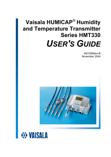
Vaisala HUMICAP Humidityand Temperature TransmitterSeries HMT330USER'S GUIDEM210566en-BNovember 2004
PUBLISHED BYVaisala OyjP.O. Box 26FIN-00421 HelsinkiFinlandPhone (int.): ( 358 9) 894 91Fax:( 358 9) 8949 2227Visit our Internet pages at http://www.vaisala.com/ Vaisala 2004No part of this manual may be reproduced in any form or by anymeans, electronic or mechanical (including photocopying), nor may itscontents be communicated to a third party without prior writtenpermission of the copyright holder.The contents are subject to change without prior notice.
Table of ContentsCHAPTER 1GENERAL INFORMATION. 7Safety. 7ESD Protection. 7Recycling. 8Trademarks . 8Getting Help . 8Warranty . 9CHAPTER 2PRODUCT DESCRIPTION . 10Options . 10Parts. 11Probe options . 12Warmed probe HMT337 . 12CHAPTER 3INSTALLATION. 13Mounting of the housing . 13Wall mounting. 13Without mounting plate . 13With plastic wall mounting plate (optional). 13With metal wall mounting plate (optional) . 14DIN rail kit mounting (optional). 15Pole installation with mounting plate . 16Mounting the rain shield . 16Wiring . 17Cable bushings. 17Grounding the cables . 18Transmitter housing grounding . 18Signal and power supply wiring. 19Connections to a 24 VAC power supply. 20Probe mounting . 21Beware of temperature differences . 21General instructions for the probes with a cable. 21HMT333 for general use . 23HMT334 for pressurized spaces . 23HMT335 for high temperatures . 24HMT337 for demanding processes . 25HMT338 for pressurized pipelines/oils . 25VAISALA 3
User's GuideCHAPTER 4OPERATION .28Display/keypad (optional) .28Main view.28Graphical view .29Menus and navigation .30Changing the language setting.31Rounding setting.31Display backlight setting .31Display contrast setting .32Keypad lock (keyguard).32Menu PIN lock .32Serial interface connections.33Connections.33Terminal program connection.34List of serial commands .36Operation and settings .37Getting the measurement message from serial line.37Formatting the serial line message .39Changing the quantities and units .41Pressure compensation setting .43User port serial settings.44Data Filtering .47Device information.47Reverting the factory settings by using the display/keypad 49Resetting the transmitter by using serial line.50Locking the menu/keypad by using serial line.50Data Recording.51Selecting the data recording quantities .51Getting the recorded data.51Deleting the recorded files.53Windows based MI70 Link program for data handlingand real-time monitoring with PC .53Analog output settings .54Changing the output mode and range.54Changing and scaling the analog output quantities .55Analog output tests.57Analog output fault indication setting.57CHAPTER 5MAINTENANCE.59Cleaning.59Changing the probe filter.59Calibration and adjustment .59Changing the sensor .60Error states.60Vaisala Service Centers .62CHAPTER 6CALIBRATION AND ADJUSTMENT .63Opening and closing the adjustment mode.634 M210566en-B
Relative humidity adjustment . 64Relative humidity adjustment after sensor change. 68Temperature adjustment . 68Analog output adjustment. 70Feeding the adjustment information . 71CHAPTER 7SPECIFICATIONS. 73Performance . 73Inputs and outputs . 76Operating conditions . 77Materials . 77Options and accessories. 78DIMENSIONS (IN MM) . 79APPENDIX 1CALCULATION FORMULAS. 82APPENDIX 2POWER SUPPLY MODULE (OPTIONAL) . 84Installation. 84Wiring . 85Technical Specifications of the power supply module . 85Warnings . 86APPENDIX 3GALVANIC ISOLATION FOR OUTPUTS. 88Installation. 88APPENDIX 4THIRD ANALOG OUTPUT (OPTIONAL) . 89Installation and wiring . 89Technical specifications for analog output module . 90APPENDIX 5RELAYS (OPTIONAL) . 91Installation and wiring . 91Operation of the relays . 93Setting the relay outputs . 94Testing the operation of relays . 96Technical specifications for relay modules. 97VAISALA 5
User's GuideAPPENDIX 6RS-422/485 INTERFACE (OPTIONAL) .98Installation and wiring.98Operation.99Networking commands .101Technical specifications of the RS-485 module .103APPENDIX 7WIRING OF THE OPTIONAL 8-POLE CONNECTOR.104APPENDIX 8TEMPERATURE PROBE (OPTIONAL) .105APPENDIX 9CHEMICAL PURGE (OPTIONAL) .106General .106Automatic chemical purge (Interval purge) .107Manual chemical purge.107Chemical Purge in power up .107Starting the chemical purge .108APPENDIX 10SENSOR HEATING (OPTIONAL).111General .111Setting the humidity sensor heating .111Sensor heating ON/OFF.111Setting the heating parameters .112APPENDIX 11PROBE INSTALLATION KITS AND INSTALLATION EXAMPLES .113Duct installation kits (for HMT333/337/335) .113Duct installation kit for T-probe (for HMT337) .114Pressure tight Swagelok installation kits (for HMT337) .115RH probe installation .115Temperature probe installation.115Examples of vapour tight installations with cable gland .116RH-probe installations (for HMT333/337).116T- probe installations (HMT337) .117Example of the climate chamber installation .118Example of the installation through a roof .119Ball valve installation kit (for HMT338).120Meteorological Installation kit (for HMT337).1216 M210566en-B
Chapter 1 General InformationCHAPTER 1GENERAL INFORMATIONSafetyThroughout the manual, important safety considerations arehighlighted as follows:WARNINGWarning alerts you to a serious hazard. If you do not read and followinstructions very carefully at this point, there is a risk of injury oreven death.CAUTIONCaution warns you of a potential hazard. If you do not read andfollow instructions carefully at this point, the product could bedamaged or important data could be lost.NOTENote highlights important information on using the product.ESD ProtectionElectrostatic Discharge (ESD) can cause immediate or latent damageto electronic circuits. Vaisala products are adequately protectedagainst ESD for their intended use. However, it is possible to damagethe product by delivering electrostatic discharges when touching,removing, or inserting any objects inside the equipment housing.To make sure you are not delivering high static voltages yourself:- Handle ESD sensitive components on a properly grounded andprotected ESD workbench. When this is not possible, groundVAISALA 7
User's Guideyourself to the equipment chassis before touching the boards.Ground yourself with a wrist strap and a resistive connection cord.When neither of the above is possible, touch a conductive part ofthe equipment chassis with your other hand before touching theboards.- Always hold the boards by the edges and avoid touching thecomponent contacts.RecyclingRecycle all applicable material.Dispose of batteries and the unit according to statutory regulations.Do not dispose of with regular household refuse.TrademarksHUMICAPâ is a registered trademark of Vaisala. Microsoft , andWindows are registered trademarks of Microsoft Corporation in theUnited States and/or other countries.Getting HelpContact Vaisala technical support:E-mailhelpdesk@vaisala.comTelephone 358 9 8949 789Fax 358 9 8949 7908 M210566en-B
Chapter 1 General InformationWarrantyVaisala hereby represents and warrants all Productsmanufactured by Vaisala and sold hereunder to befree from defects in workmanship or material duringa period of twelve (12) months from the date ofdelivery save for products for which a specialwarranty is given. If any Product proves however tobe defective in workmanship or material within theperiod herein provided Vaisala undertakes to theexclusion of any other remedy to repair or at its ownoption replace the defective Product or part thereoffree of charge and otherwise on the same conditionsas for the original Product or part without extensionto original warranty time. Defective parts replaced inaccordance with this clause shall be placed at thedisposal of Vaisala.Vaisala also warrants the quality of all repair andservice works performed by its employees toproducts sold by it. In case the repair or serviceworks should appear inadequate or faulty and shouldthis cause malfunction or nonfunction of the productto which the service was performed Vaisala shall atits free option either repair or have repaired orreplace the product in question. The working hoursused by employees of Vaisala for such repair orreplacement shall be free of charge to the client.This service warranty shall be valid for a period ofsix (6) months from the date the service measureswere completed.This warranty is however subject to followingconditions:a) A substantiated written claim as to any allegeddefects shall have been received by Vaisalawithin thirty (30) days after the defect or faultbecame known or occurred, andb) The allegedly defective Product or part shall,should Vaisala so require, be sent to the works ofVaisala or to such other place as Vaisala mayindicate in writing, freight and insurance prepaidand properly packed and labelled, unless Vaisalaagrees to inspect and repair the Product orreplace it on site.a) normal wear and tear or accident;b) misuse or other unsuitable or unauthorized use ofthe Product or negligence or error in storing,maintaining or in handling the Product or anyequipment thereof;c) wrong installation or assembly or failure toservice the Product or otherwise follow Vaisala'sservice instructions including any repairs orinstallation or assembly or service made byunauthorized personnel not approved by Vaisalaor replacements with parts not manufactured orsupplied by Vaisala;d) modifications or changes of the Product as wellas any adding to it without Vaisala's priorauthorization;e) other factors depending on the Customer or athird party.Notwithstanding the aforesaid Vaisala's liabilityunder this clause shall not apply to any defectsarising out of materials, designs or instructionsprovided by the Customer.This warranty is expressly in lieu of and excludes allother conditions, warranties and liabilities, expressor implied, whether under law, statute or otherwise,including without limitation any implied warrantiesor merchantability or of fitness for a particularpurpose and all other obligations and liabilities ofVaisala or its representatives with respect to anydefect or deficiency applicable to or resultingdirectly or indirectly from the Products suppliedhereunder, which obligations and liabilities arehereby expressly cancelled and waived. Vaisala'sliability shall under no circumstances exceed theinvoice price of any Product for which a warrantyclaim is made, nor shall Vaisala in anycircumstances be liable for lost profits or otherconsequential loss whether direct or indirect or forspecial damages.This warranty does not however apply when thedefect has been caused throughVAISALA 9
User's GuideCHAPTER 2PRODUCT DESCRIPTIONVaisala HUMICAP Humidity and Temperature Transmitter Series HMT330 providesreliable humidity measurement in wide range of applications. Analog outputs can bechosen between current and voltage signals. Alternatively the following digital outputscan be selected: RS-232 (standard) or RS-422/485 (optional). The transmitter measuresand calculates the following quantities:QuantityRelative humidityTemperatureMetric Unit%RH CNon Metric Unit%RH FOptionally available the following quantities:QuantityDewpoint /FrostpointDewpointAbsolute humidityMixing ratioWetbulb temperatureHumid air volume/ dry air volumeWater vapour pressureSaturation water vapour pressureEnthalpyDifference of T and Td/fMetric Unit C C3g/mg/kg CppmhPahPakJ/kg CNon Metric Unit F F3gr/ftgr/lb Fppm2lb/in2lb/inBtu/lb FOptions-several probes for different applicationsuser friendly displaycalculated output quantities availabledifferent probe mounting kits, sensor protection options and probe cable lengthsdifferent transmitter mounting kitschemical purge for applications where there is a risk of interfering chemicals in themeasuring environmentwarmed probe and sensor heating for high humidity conditions (HMT337)optional modules: isolated power supply, power supply module, RS-422/485module, additional analog output module, relay moduleadditional temperature sensor (HMT337)10 M210566en-B
Product descriptionPartsHMT330 Transmitter bodyProbeCover LEDDisplay with keypad(optional)Cover screws (4 pcs)FilterCable glands:Signal poweringcableService port(RS-232)Adjustmentbuttons andled.(Chemicalpurgebuttons).Cables foroptionalmodulesA yellow plastic probe cover is protecting thesensor head during the transportation.Remove the cover when measuring.Dip switchesfor analog Power supply and signaloutputwiring screw mperatureprobe cable(optional)Relay /RS-422/485module(optional)Analog output/relay module(optional)GroundingconnectorPower supplymodule(optional)HumidityprobecableVAISALA 11
User's GuideProbe optionsHMT331for wallmountingHMT333for generaluse (probehead 12mm)HMT334HMT335HMT337HMT338for pressurizedspaces up to 100barfor hightemperaturesup to 180 C(long probe242 mm,vapor tight)fordemandingprocesses(optionallywarmed andvapor tightprobe head)for pressurizedpipelines (40 bar,ball valve)Probe cable lengths: 2, 5 and 10 m.Warmed probe HMT337Temperature difference between the probe head and external environment can cause arisk of condensation on the sensor. A wet probe cannot observe the actual humidity inthe ambient air. If the condensed water is contaminated, the life span of the probe mayshorten and calibration may change.HMT337 probe shall be used in applications where condensation can occur due to highhumidity and rapid humidity changes. The warmed probe head is heated continuouslyso that its temperature is always higher than in environment. This prevents condensationon the probe. The power consumption of the warmed probe is slightly higher than otherprobes.12 M210566en-B
InstallationCHAPTER 3INSTALLATIONMounting of the housingWall mountingWithout mounting plateFasten the transmitter to the wall with 4 screws M6 (not provided).ø 796169With plastic wall mounting plate (optional)The mounting plate (Vaisala order code 214829) can be installed directly onwall or onto a standard wall box (also US junction box). When wiringthrough back wall, remove the plastic plug from the wiring hole beforemounting.VAISALA 13
User's Guide1.Mount the plate to wallwith 4 screws M6 (notprovided)2. Fasten HMT330 to themounting plate with 4fixing screws(provided)The arched side up !Plasticmounting plateHoles for wall/junction boxmounting.1836.2596.584104115.810.58.54.5133s 9.5 mm59Plastic mounting plate, dimensions (mm)With metal wall mounting plate (optional)Metal mounting plate is included in Rain shield kit and pole installation kit.This side up ! The holes for rain shield shallbe in the upper edge.1.Mount the plate to wallwith 4 screws M8(not provided)2.Fasten HMT330 to themounting plate with 4fixing screws M6(provided)14 M210566en-B
961791108538M6B (2: 1)AMetal mounting plate, dimensions (mm)DIN rail kit mounting (optional)Din rail kit includes a plastic wall mounting plate, 2 spring holders and 2screws M4 x 10 DIN 7985 (Vaisala order code 215094).1.Attach two spring holders to the plastic mounting plate by using thescrews provided with an installation kit.2.Fasten HMT330 to the plastic mounting plate with 4 screws provided.3.Press the transmitter onto the DIN rail so that the spring holders snapinto the rail.Din rail kit mountingVAISALA 15
User's GuidePole installation with mounting platePole installation kit (Vaisala order code 215108) includes the metalmounting plate and 2 mounting nuts for pole mounting.Vertical poleFixing brackets (2 pcs)M8 (provided)for 30.102 mm poles.Vertical poleMounting nuts M8 (4 pcs)Horizontal poleMounting nuts M8 (4 pcs)Mounting the rain shieldVaisala order code: 215109.1.Fasten the rain shield tothe metal mounting platewith 2 (M6) mountingscrews (provided )2.Fasten the mountingplate with rain shield tothe wall or to the pole(see pole installation).3.Fasten the HMT330 to the mounting plate4 fixing screws (provided)16 M210566en-B
InstallationWiringCable bushingsA single electrical cable with a screen and three to ten wires isrecommended for power and analog/serial connections. The cable diametershould be 8.11 mm. The number of cable bushings depends on thetransmitter options. See the following recommendations for the cablebushings:Cable forsignal/powering 8.11 mmCable for optional powermodule 8.11 mmCable foroptionalmodule 8.11 mmNOTEWhen there is high electric noise level (e.g. near powerful electricmotor) in the operating environment it is recommended to use shieldedcable or take care that the signal cables are separated from other cables.VAISALA 17
User's GuideGrounding the cablesThe screen of the electrical cable must be grounded properly to achieve thebest possible EMC performance.1. Cut back outer sheath to desired length.2. Cut back screen braiding or screen foil todimension X (see figure 3).3. Push the domed cap nut (item 1) and the sealinsert with contact socket of the gland (item2 3) onto the cable as shown in the diagram.4. Bend over the screen braiding or screen foilby about 90 (item 4).5. Push the seal insert with the contact socketof the gland (item 2 3) up to the screenbraiding or screen foil.6. Mount lower part (item 5) on the housing.7. Push the seal with the contact socket of thegland and (item 2 3) flush into the lowerpart (item 5).8. Screw the domed cap nut (item 1) onto thelower part (item 5).Transmitter housing groundingIn case you need to ground the transmitter housing, the grounding connectoris found inside the housing (see picture on page 11). Note anyhow that theprobe head is connected to the same potential as the housing. Make sure thatdifferent groundings are made to the same potential. Otherwise harmfulground currents may be generated.If it is needed to have galvanic isolation of the power supply line from theoutput signals, HMT330 can be ordered with optional output isolationmodule, see Appendix 3. This module prevents harmful grounding loops.18 M210566en-B
InstallationSignal and power supply wiringWhen connecting transmitter with 8-pole connector, see Appendix 7.Power supply terminals10.35 VDC, 24 VACUser port(RS-232 terminals)Analog signal terminalsScrew terminal block on the motherboardWARNINGMake sure that you connect only de-energized wires.1. Open the transmitter cover by taking out the four cover screws.2. Insert the power supply wires and signal wires through the cablebushing in the bottom of the transmitter; see the grounding instructionsin the previous sections.3. Connect the analog output cables to terminals: Ch1 , Ch1-, Ch2 , Ch2-.Connect the RS-232 user port cables to terminals RxD, GND and TxD,more about the RS-232 connection on page 33.4. When wiring RS-485 module, relay module or additional analog outputmodule, see Appendices 4, 5 and 6.5. Connect the power supply wires to the connectors: POWER 10.35V 24V ( ) and (-) terminals. (If using AC voltage, connect always phase topower supply ( ) and 0 to power supply (-)). When wiring the powersupply module, see Appendix 2.6. Turn on the power. The indicator led on the cover lit continuouslyduring normal operation.7. Close the cover and replace the cover screws. The transmitter is readyfor use.VAISALA 19
User's GuideConnections to a 24 VAC powersupplySeparate floating supply for each transmitter is recommended (see figure A).If you have to connect several transmitters to one AC supply, the phase ( )must always be connected to ( ) connector of each transmitter (see figureB).CAUTIONIn case you have only one AC supply, never connect same wire tothe connector of a transmitter and to the - connector of anotherone. This will short-circuit the transformer.20 M210566en-B
InstallationProbe mountingBeware of temperature differencesIn humidity measurement and especially in calibration it is essential thattemperature of the probe and measuring environment is the same. Even asmall difference in temperature between the environment and the probecauses an error. As the curve below shows, if the temperature is 20 C andthe relative humidity 100 %RH, a difference of 1 C between theenvironment and the probe causes an error of 6 %RH.1098dRH (%RH)76543210-40-20020406080100Temperature ( C)Measurement error at 100 %RH when the difference between the ambient andsensor temperature is 1 C.General instructions for the probeswith a cableMount the probes with a cable with the sensor head horizontally; this way,any water condensing on the tube cannot flow onto the sensor.VAISALA 21
User's GuideInsulate the cableIf needed, protect theprobe from drippingwater (or otherliquids).Let the cable hang loosely.This prevents condensedwater running to the sensoralong the cable.When there is no alternative but to install the sensor head in the processvertically, the point of entry must be carefully insulated. The cable mustalso be allowed to hang loosely as this prevents any condensed water fromrunning onto the sensor head along the cable.to be sealedInsulate the cableto be insulatedLet the cable hang loosely.This prevents condensedwater running to the sensoralong the cable.NOTEPlease do not attach a heated probe (HMT337) to a metal structures toavoid condensation problems caused by heat conduction along themetal.If the process temperature is much higher than that of the environment, thewhole sensor head and preferably plen
Vaisala HUMICAP Humidity and Temperature Transmitter Series HMT330 USER'S GUIDE M210566en-B November 2004






![Humidity101 HumidityTheory.pptx [Read-Only] - Vaisala](/img/46/humidity101-humiditytheorytermsdefinitions.jpg)
