Transcription
LASERSPEED 8000/9000I/O MODULEINSTRUCTION HANDBOOK- installation, setup, technical reference -www.betalasermike.comManual Part Number: 93342 Manual Drawing Number: 0921-01516 English Revision E Copyright Dec 2013
LaserSpeed 8000/9000 I/O Module Instruction HandbookContentsProprietary Statement . 3European Commission Requirements . 4Declaration of Conformity . 5Safety Information . 6General Safety Information .6Intended Use .6Introduction . 7I/O Module Front Panel .7Installation . 8Rear Panel Pin-outs.8Parallel Outputs .16Parallel Outputs .20Elongation/Synchronization .24Master/Slave I/O Modules.24Synchronization .26Elongation/Differential Speed Calculation .27Setup .28Data Format.28Serial Communications .31I/O Module Configuration Commands .34I/O Module-to-LaserSpeed Communication .60Operation .61Understanding the Front Panel .61Profibus Operation .62Ethernet Network Operation .75Servicing Your Equipment .79Returning Equipment for Service .79Specifications .80Stand-alone Dimensions .80Rack Mounting Dimensions .80Bottom Mounting Dimensions .81General Specifications .82Index.84Part No. 93342 / Drawing No. 0921-01516Page 2 of 84Revision E (Dec 2013)
LaserSpeed 8000/9000 I/O Module Instruction HandbookProprietary StatementProprietary StatementManufacturer/DistributorBeta LaserMike, 8001 Technology Blvd., Dayton, OH 45424, USAAbout This ManualThis manual contains descriptions, drawings, and specifications for a Beta LaserMike product. Equipment orproducts made prior to or subsequent to the publication date of this manual may have parts, features, options,or configurations that are not covered by this manual. Specifications contained herein are subject to changeby Beta LaserMike without prior notice. Beta LaserMike is not responsible for errors or omissions that may becontained herein or for incidental or consequential damages in connection with the furnishing or use of thisinformation.The information contained in this manual is the property of Beta LaserMike. The information disclosed in thisdocument is furnished in confidence and upon the condition that individual and corporate intellectual rights,whether patented or not, will be respected. If this document is supplied on removable media (e.g. CD), anelectronic copy (stored on-site) and one printout is permitted. If this document is supplied in printed form, nopart of this document may be reproduced or scanned without the prior written consent of Beta LaserMike.This document may not be distributed or circulated to third parties.Limited WarrantyBeta LaserMike will correct by repair, or at Beta LaserMike‘s option, by replacement, F.O.B Beta LaserMike’splant, any defect in workmanship or material in any equipment manufactured by Beta LaserMike whichappears under normal and proper use within twelve months from the date of shipment (eighteen months forOEM’s), provided Beta LaserMike is given reasonable opportunity to inspect the alleged defective equipmentat the place of its use and under conditions of its use.EXCLUSIONS: This warranty does not cover products which have been modified, altered, or repaired by anyother party than Beta LaserMike or its authorized agents. Furthermore, any product which has been, or issuspected of being damaged as a result of negligence, misuse, incorrect handling, servicing, or maintenance;or has been damaged as a result of excessive current/voltage or temperature; or has had its serial number(s),any other markings, or parts thereof altered, defaced, or removed will also be excluded from this warranty.WARRANTY SERVICE AT CUSTOMER SITE: Warranty service performed at the customer’s facility will befree of charge for parts and labor; however, the customer will be liable for transportation and living expensesof personnel dispatched to effect such repair. A purchase order or other written confirmation of theacceptance of these charges, signed by an authorized individual, will be required prior to commencement ofrepairs. Additional charges may be assessed the customer if: 1) The equipment is not made available on atimely basis, 2) The equipment is found to be without fault, and/or 3) It is determined the equipment is notunder warranty, whether by expiration of the warranty or any act which voids the warranty.OTHER THAN AS SET FORTH HEREIN, BETA LASERMIKE MAKES NO WARRANTIES, EXPRESSED ORIMPLIED, OF MERCHANTABILITY AS TO THE EQUIPMENT MANUFACTURED BY IT, AND THERE ARENO EXPRESSED OR IMPLIED WARRANTIES WHICH EXTEND BEYOND THE DESCRIPTION ON THEFACE THEREOF. Beta LaserMike’s obligation to correct defects in such equipment by repair or replacementin accordance with the foregoing provisions is in lieu of any other warranties, expressed or implied, and in noevent shall Beta LaserMike be liable for incidental or consequential damages. No service of Beta LaserMike’sequipment is permitted during the warranty period without the specific written consent of Beta LaserMike.Part No. 93342 / Drawing No. 0921-01516Page 3 of 84Note:For informationabout servicingand returningyour equipment,see the sectionat the end of thismanual.Revision E (Dec 2013)
LaserSpeed 8000/9000 I/O Module Instruction HandbookEuropean Commission RequirementsEuropean Commission RequirementsThis equipment is intended for use in a heavy industrial environment. The equipment generates, uses andcan radiate radio frequency energy and, if not installed and used in accordance with the instructions, maycause harmful interference to other equipment. There is no guarantee that interference will not occur in aparticular installation. If this equipment does cause harmful interference to other equipment the user isencouraged to try to correct the interference by one or more of the following measures:- Re-orientate or relocate the equipment.- Increase the separation between the pieces of equipment.- Connect the pieces of equipment on separate mains circuits.- Ensure that the relevant items of equipment are properly and securely earthed to a common earth pointusing adequately sized cable or other means of connection.Where supplied or specified, shielded interconnection cables must be employed with this equipment to ensurecompliance with the pertinent RF limits. Changes or modifications not expressly approved by the companycould void the user’s authority to operate the equipment.This product has been rigorously tested to comply with the European EMC (Electromagnetic Compatibility)Directive. With regard to this, Beta LaserMike recommends that any non-Beta LaserMike peripheralequipment is CE marked for the Heavy Industrial environment (EN50082-2). Beta LaserMike alsorecommends that any cables not supplied by Beta LaserMike, but used for powering Beta LaserMikeequipment, be built using good EMC practices (i.e. cables with braided shield, and connectors with 360 termination of the braid to a metal/metalised shell connector at both ends). If you have any questionsregarding this, contact the Beta LaserMike Service Department.Part No. 93342 / Drawing No. 0921-01516Page 4 of 84Revision E (Dec 2013)
LaserSpeed 8000/9000 I/O Module Instruction HandbookDeclaration of ConformityDeclaration of ConformityPart No. 93342 / Drawing No. 0921-01516Page 5 of 84Revision E (Dec 2013)
LaserSpeed 8000/9000 I/O Module Instruction HandbookSafety InformationSafety InformationGeneral Safety Information Under NO circumstances should the earth/ground safetyconnections be broken – internal damage to sensitiveelectronic components may occur and at worstelectrocution to personnel may result. The protective conductor terminal symbol is shown to theright. This equipment must be earthed/grounded. Relays and associated wiring are rated for SELV levels i.e.60 Vdc & 30 vac rms. These levels must not be exceeded. Maintenance, repairs and electrical connections should beperformed by a suitably qualified person for the country ofinstallation. Do not position the equipment so that it is difficult tooperate the disconnecting device.Note: If theequipment is notused in themanner specifiedby BetaLaserMike, theprotectionprovided by theequipment maybe impaired.Intended UseIf the equipment is used in a manner not specified by the manufacturer, theprotection provided by the equipment may be impaired.Part No. 93342 / Drawing No. 0921-01516Page 6 of 84Revision E (Dec 2013)
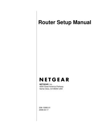
LaserSpeed 8000/9000 I/O Module Instruction HandbookIntroductionIntroductionThe LaserSpeed I/O Module is used to translate the serial output data, Speed,Length and Gauge Status, from a LaserSpeed 8000 or 9000 Series Gauge to aparallel output. Optional Profibus and Ethernet field bus are also available in theI/O Module. The I/O Module connects to the LS9000/LS8000 gauge through agauge cable via an RS422 connection, and provides a pass-through connectorfor direct access to all the Inputs and Outputs of the LS9000/LS8000 SeriesGauge. A Light Stack connector provides signals to drive a visual indicator (alight stack) to display the status of the gauge. The I/O Module can also be usedcalculate the Elongation Ratio/Differential Speed between two LS8000/LS9000Series gauges. In addition, the I/O Module can be used to synchronize theoutputs of multiple gauges to output their data at the same time.I/O Module Front PanelPart No. 93342 / Drawing No. 0921-01516Page 7 of 84Revision E (Dec 2013)
LaserSpeed 8000/9000 I/O Module Instruction HandbookInstallationInstallationRear Panel Pin-outsThe following sections describe the various connections to the I/O Module’s rearpanel. Refer to the LS9000/LS8000 Instruction Handbook for further informationabout connections to the Gauge.PowerAccepts IEC 320 power cords. AC power requirements are 90-260VAC,50/60Hz, 1.5Amps.I/O SetupA computer can be connected to this port using a straight-through 9-pin serialcable for diagnostics and configuration. LaserTrak 4.0 can be used to configurethe LaserSpeed gauge through this port. A NULL modem is not required.DisplayConnects directly to the LaserSpeed I/O Module Display, part number 85871.This is an LCD indicator that shows the current Length, Velocity, Quality Factor,and Status.Part No. 93342 / Drawing No. 0921-01516Page 8 of 84Revision E (Dec 2013)
LaserSpeed 8000/9000 I/O Module Instruction HandbookInstallationLight StackOutput to drive a light stack. Outputs pull up to 24 volts.ColorMeaningLaser Emission?GreenLaser OFFNoYellowLaser ON, Shutter is CLOSEDNoRedLaser ON, Shutter is OPENYesLaserSpeed GaugeTO GAUGE37 pin D connector for connection to the LaserSpeed gaugecable. This connector is compatible with all cables that havepart number 85277.PASS-THROUGHPasses signals from the DB25 connector on aLS9000/LS8000. The pinout of this connector is compatiblewith 25-pin LaserSpeed breakout boxes. Signal descriptionsare listed in a table below.ETHERNETPass-through connector for the LS9000/LS8000 gauge’soptional Ethernet connection that provides a directconnection to the gauge over Ethernet. If the attachedgauge does not have the Ethernet option installed, then thisconnector is not used.RS-232Pass-through connector for the LS9000/LS8000 gauge’s RS232 serial port. This connector can be connected to a PCusing a straight-through DB9 serial cable. LaserTrak or aterminal program can be used to communicate directly withthe gauge via this serial port.Part No. 93342 / Drawing No. 0921-01516Page 9 of 84Revision E (Dec 2013)
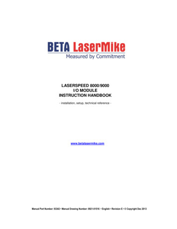
LaserSpeed 8000/9000 I/O Module Instruction HandbookInstallationSYNC IN and OUT connectorUsed to connect multiple I/O modules together for gauge-gauge synchronization,and Elongation/Differential Speed calculation. The Sync Out connector of oneI/O module connects to the Sync In connector of the next I/O Module with astraight-through RJ-45 cable.INConnects to the Master I/O module.OUTConnects to SYNC IN of the next I/O Module in the Daisy Chain.unconnectedOUTto Masterto SlaveI/O ModuleINOUTto Masterto SlaveI/O ModuleINto MasterunconnectedOUTINto Slaveto MasterI/O Moduleto SlaveI/O Moduleto l OutputsSTATUSParallel Output for Status / Interlock Control / Shutter ControlVELOCITYParallel output for VelocityLENGTH/ELONGATION Parallel output for Length or Elongation RatioThe LENGTH/ELONGATION port can output either Length or the ElongationRatio between two gauges, depending on the I/O Module’s position in thesystem. All I/O Modules except for the last I/O module in the Daisy Chaincalculate the Elongation Ratio or Differential Speed. The last I/O module in theDaisy Chain always outputs Length on the Length/Elongation port. All other I/OModules output Elongation Ratio if the port is configured for Auto-ElongationMode. The I:Elongation command is used to configure this mode. By default,the I:Elongation setting should be set to 1 on all I/O Modules. This will causethe I/O Module to automatically output Elongation if it is being calculated. Seethe Elongation/Synchronization section for more information about Elongation.Note: Elongation Ratio will only be calculated when two gauges are synchronizedtogether by connecting the Sync Out of one I/O Module to the Sync In of theother I/O Modules.Part No. 93342 / Drawing No. 0921-01516Page 10 of 84Revision E (Dec 2013)
LaserSpeed 8000/9000 I/O Module Instruction HandbookInstallationConnectionsConnect the LaserSpeed 8000/9000 to the TO GAUGE input using the suppliedcable.Status pins 17, 18, and 26 and 19, 27, and 30 must be connected as shown forthe gauge to operate. An interlock shunt connector is supplied with the interlockconnections pre-wired. Beta LaserMike recommends that you use the suppliedkey switch to operate the Laser Interlock. This will provide you with a lasershutoff for maintenance or material changes.Pin 19 Laser Interlock (-)Pin 27 Shutter Interlock (-)Pin 18 Laser Interlock ( )Pin 26 Shutter Interlock ( ) 5-24VDC 5-24VDCGroundGroundNote: The Setupsection of thismanual will helpyou configure theI/O Module withthe LaserSpeedGauge. Use theLaserTraksoftware to setupthe LaserSpeedGauge itself.19 18 173027 26Pin 17 5VPin 18 Laser Pin 19 LaserPin 26 Shutter Pin 27 ShutterPin 30 GroundPart No. 93342 / Drawing No. 0921-01516Page 11 of 84Revision E (Dec 2013)
LaserSpeed 8000/9000 I/O Module Instruction HandbookInstallationPass-through Connector PinoutMale 25-Pin D-SubminiaturePinPin Description1RS232 Transmit (From Gauge to User)2RS232 Receive (From User to Gauge)3Phase A True – Fixed Output4Phase A False – User Selectable5Phase A False – Fixed Output6Phase B True – User Selectable7Phase B True – Fixed Output8Phase B False – User Selectable9Phase B False – Fixed Output10Material Present Input11Signal Ground for Inputs/Outputs/Serial12No Connection13No Connection14Measurement Direction Input15Phase A True – User Selectable16No Connection17No Connection18Length Reset 119Signal Ground for Inputs/Outputs/Serial20User Vin: Voltage Input for Isolated Pulse Outputs (5 to 28 V DC). Thevoltage supplied will be the voltage level of the pulse outputs supplied bythe LS4000-1. If a Voltage is not supplied, the pulse outputs will be TTLlevel, or 3.7 volts minimum. Because this voltage input is isolated fromthe power input, it must be references to one of the Signal Ground pins.For example, if you want the pulse outputs to be 12 V outputs, use a 12V power supply by connecting the positive terminal to pin 20 and theground terminal pin to pin 11, 19, or 21.21Signal Ground for Inputs/Outputs/Serial22Index (Printer) Pulse True23Index (Printer) Pulse False24 24V Power Input (Fused)25 24V Power Input (Fused)Part No. 93342 / Drawing No. 0921-01516Page 12 of 84Revision E (Dec 2013)
LaserSpeed 8000/9000 I/O Module Instruction HandbookInstallationGauge Connector PinoutFemale 37-Pin D-SubminiatureThe Gauge connector is connected to the LS9000/LS8000.PinPin Description1RS232 Transmit (From Gauge to User)2RS232 Receive (From User to gauge)3Phase A True – High Speed output4Phase A False – User Selectable5Phase A False – High Speed Output6Phase B True – User Selectable7Phase B True – Highs Speed Output8Phase B False – User Selectable9Phase B False High Speed Output10Measurement Hold Input, can be activated by I/O Module11Signal Ground for Inputs/Outputs/Serial12Power Ground for 24V13Power Ground for 24V14Measurement Direction Input 115Phase A True – User Selectable16Laser Interlock17Shutter control18Length Reset 1, can be activated by I/O Module19Signal Ground for Inputs/Outputs/Serial20User Vin: Voltage Input for Isolated Pulse Outputs (5 to 28 V DC). Thevoltage supplied will be the voltage level of the pulse outputs supplied bythe LS4000-1. If a Voltage is not supplied, the pulse outputs will be TTLlevel, or 3.7 volts minimum. Because this voltage input is isolated from thepower input, it must be references to one of the Signal Ground pins. Forexample, if you want the pulse outputs to be 12 V outputs, use a 12 Vpower supply by connecting the positive terminal to pin 20 and the groundterminal pin to pin 11, 19, or 21.21Signal Ground for Inputs/Outputs/Serial22Index (Printer) Pulse True23Index (Printer) Pulse False24 24V Power Output (Fused)25 24V Power Output (Fused)26RS422 Transmit 27RS422 Transmit -Part No. 93342 / Drawing No. 0921-01516Page 13 of 84Revision E (Dec 2013)
LaserSpeed 8000/9000 I/O Module Instruction HandbookInstallation28RS422 Receive 29RS422 Receive -30Ana log Output voltage31Signal ground32Core sync input 33Core sync input-34Ethernet tx 35Ethernet rx-36Ethernet tx-27Ethernet rx-Note 1: User Input requiring 5 to 28 V to activate.General Note: The Laser Interlock is in series with the front panel switch.Gauge RS-232 ConnectorFemale 9-Pin D-Subminiature1NC2RS232 Xmit from gauge3RS232 Rec to gauge4NC5Signal groundI/O Setup ConnectorFemale 9-Pin D-Subminiature1NC2RS232 Xmit from I/O module3RS232 Rec to I/O module4NC5Signal groundPart No. 93342 / Drawing No. 0921-01516Page 14 of 84Revision E (Dec 2013)
LaserSpeed 8000/9000 I/O Module Instruction HandbookInstallationLight Stack Connector PinoutFemale 9-Pin D-Subminiature1Pulled up to 24 volts for red light stack2Pulled up to 24 volts for yellow light stack3Pulled up to 24 volts for green light stack4 24 volts524 volts ground6 24 volts7Reserved – Do Not Connect8Reserved – Do Not Connect9NCNotes: Pin 1 (or Red on the Light Stack) is active when the Status Input from theLS9000/LS8000 shows power is being sent to the laser and that theShutter is open. Pin 2 (or Yellow on the Light Stack) is active when the Status Input fromthe LS9000/LS8000 shows power is being sent to the laser and theshutter is closed. Pin 3 (or Green on the Light Stack) is active when there is no powerbeing sent to the laser. Pin 4 and 6 are 24 volts at 1 amp for the Light Stack. Pin 5 is signal ground.When the red and yellow lamps flash alternately, this indicates that there are nocommunications from the LaserSpeed gauge.Part No. 93342 / Drawing No. 0921-01516Page 15 of 84Revision E (Dec 2013)
LaserSpeed 8000/9000 I/O Module Instruction HandbookInstallationParallel OutputsThere are three, 37-pin D-Subminiature, Parallel output ports:Parallel PortDescriptionStatusOutputs the system status and accepts control inputsLength/ElongationOutputs either Length from the gauge or ElongationRatio that is Calculated in the I/O Module.SpeedOutputs the Velocity measurement from the gaugeStatus SignalsStatus Signals (pins numbered 1–16) are generated as solid state closures. Thecontacts close when the condition is true. The contact maximum voltage andcurrent ratings are: 200mA at 30 VAC/VDC for resistive loads.System input signals (pins numbered 20–31) are optically-isolated input signalsbetween 5VDC and 30VDC. The input should be applied to the INPUT pin, andground should be applied to the INPUT– pin for each signal used. Refer to thefollowing table pin-out information.Part No. 93342 / Drawing No. 0921-01516Page 16 of 84Revision E (Dec 2013)
LaserSpeed 8000/9000 I/O Module Instruction HandbookInstallationPin Assignment for System StatusPinSignal NameI/ODescription1Material Present 2Material Present-Output Contact Closure Output indicating the Material Presentstate.OutputClosed Material is PresentOpen Material is Not Present34Valid Measurement Output Contact Closure Output indicating when the LaserSpeedgauge is making valid measurementsValid Measurement – OutputClosed LaserSpeed gauge is MeasuringOpen LaserSpeed gauge is Not Measuring5System Ready 6System Ready –Output Contact Closure Output indicating if the system is readyto measure. This output is closed when the Laser is ON,Outputthe Shutter is Open, and the Laser is at the correcttemperature.Closed System is Ready to MeasureOpen System is Not Ready to Measure7Laser Power 8Laser Power –Output Contact Closure Output indicating if the Laser Power ison.OutputClosed Laser is ONOpen Laser is OFF9ReservedOutput Reserved Contact Closure Output10ReservedOutput-11Laser Temperature 12Laser Temperature –Output Contact Closure Output indicating if the Laser is at thecorrect temperature.OutputClosed Laser Temperature is OkDo Not ConnectOpen Laser Temperature is not within tolerance13Laser Operational Output Laser is Operational: Shutter Open Laser Power14Laser Operational –Output-Closed Laser is Operational (Laser emission)Open Laser is not Operational (no Laser emission)15Comm Error 16Comm Error –Output Contact Closure Output indicating if the I/O Module iscommunicating with the LaserSpeed gauge.OutputClosed Communication OkOpen Not Communicating17 5 volts (fused, 1A)Output 5VDC Output for connection to interlock signals whenwiring as contact closure Inputs.18Laser Interlock Input 19Laser Interlock-Input-Laser Interlock input to LS9000/LS8000. Seeconnection diagram for wiring instructions. See also noteat end of table.20ReservedInput 21ReservedInput-Part No. 93342 / Drawing No. 0921-01516Do not usePage 17 of 84Revision E (Dec 2013)
LaserSpeed 8000/9000 I/O Module Instruction HandbookInstallation22External MaterialPresent Input 23External MaterialPresent –Input-24ReservedInput 25ReservedInput-26Shutter Input 27Shutter ved32Elongation Analog33GND34Velocity Analog35GND36Quality FactorAnalogThe External Material Present input is used to controlwhen the gauge will measure. The gauge will measurewhen External Material Present is active and will notmeasure when External Material Present is not active.External Material Present is enabled and disabled viaserial commands for the gauge. See Serial Commandslisting in the gauge manual.Do not useShutter Control Input to LS9000/LS8000. Seeconnection diagram for wiring instructionsDo not useGround for connection of I/O SignalsDo not useOutputElongation Ratio Analog Output. Minimum andMaximum are configurable. An output of 0Vcorresponds to the Minimum Elongation, and an outputof 2.048V corresponds to the Maximum Elongation.Elongation Analog Output groundOutputVelocity Analog Output. Minimum and Maximum areconfigurable. An output of 0V corresponds to theMinimum Velocity, and an output of 2.048V correspondsto the Maximum Velocity.Velocity analog Output groundOutputQuality Factor Analog Output – voltage output changeslinearly from Quality Factor 0 to Quality Factor 15.0 0 Quality Factor2.048V 15 Quality Factor37GNDQuality Factor Analog Output groundNote:The Laser interlock (Pins 18, 19) on the Status Port is in series with thefront panel Key Switch. The Key Switch and Pins 18 and 19 must be activated toturn on the Laser.External Material Present (MP)This is an input to the bi-directional System Status port. This input is functionalonly when the gauge is configured for External Material Present. When thismode is at a Logic Low (or No Input), measurements are enabled. When thisinput is at a Logic High (5 –30 volts), measurements are disabled.Part No. 93342 / Drawing No. 0921-01516Page 18 of 84Revision E (Dec 2013)
LaserSpeed 8000/9000 I/O Module Instruction HandbookInstallationAnalog OutputsPins 32-37 of the SYSTEM STATUS port are used for various analog outputs.Every I/O Module contains three analog outputs. Elongation Analog Output – only used when using multiple I/O modulesare configured for Synchronization. Velocity Analog Output Quality Factor Analog OutputAll analog outputs are non-isolated. You may set the scaling of the elongationand speed outputs to fit your application. See the Serial Commands section.Part No. 93342 / Drawing No. 0921-01516Page 19 of 84Revision E (Dec 2013)
LaserSpeed 8000/9000 I/O Module Instruction HandbookInstallationParallel OutputsData is updated to the bus in one of two modes. The first is called "Data Ready"mode and the other is called "Data Request" mode. In "Data Ready" mode, thesystem will automatically update the data on the Parallel Output Bus each UserUpdate Period. In "Data Request" mode, the system will update the data on theParallel Output Bus only when a Data Requested Signal is received on the DataRequest Input Pin. There are Data Request Input Pins on the Parallel Length/Elongation port and the Parallel Velocity port. The data output mode isconfigured by I:AckMode serial command:CommandParallel Port Mode I:AckMode 0Data Ready Mode I:AckMode 1Data Request ModeData Ready ModeIn Data Ready mode, the I/O module outputs data each time a new measurementis received from the LaserSpeed gauge. An optically isolated signal called "DataReady," located on the Length/Elongation and the Velocity Output connectors,are provided to indicate when data has been upated and is valid. The DataReady pulse indicates that the data bus has been updated with new data and thatthe signals on the bus are completely settled. Both Data Ready True (RisingEdge Trigger, signal driven from ground to Voltage high) and Data Ready False(Falling Edge Trigger, signal driven from Voltage high to ground) are provided.When using Data Ready True, data should be read from the bus on the risingedge of the signal, and when using Data Ready False, data should be read onthe falling edge. Either the leading edge or the active level of the signal can beused to trigger a read by your interface.Ringing on the line can occur if the cable is not properly terminated. This cancause the data to be unstable during the time of the active edge of the data readysignal. Allow for extra settling time if ringing occurs.SignalActivityData Valid On:Data Ready (True)Active HighRising EdgeData Ready (False)Active LowFalling EdgeData is valid from the time that the Data Ready signal is asserted until the timethat the next data point is received from the gauge. This time varies dependingon the gauge’s Update Rate configuration setting. See the timing specificationsbelow for detailed timing information.Part No. 93342 / Drawing No. 0921-01516Page 20 of 84Revision E (Dec 2013)
LaserSpeed 8000/9000 I/O Module Instruction HandbookInstallationData Ready (True) TimingT4DATAT1DATA READY(True)T3T2Data Ready (False) TimingT4DATAT1DATA READY(False)T3T2ParameterSymbolValueData Setup TimeT1300 µs (min.)Data Ready Pulse WidthT2ReadyLn x 500µsData Valid TimeT3Update Rate - 500µs (min.)Update RateT41-2000 msThe Data Ready Pulse Width and the Update Rate parameters can be configuredwith a serial command. See the RS-232 Configuration Commands section fordetails.Choosing the correct polarity of "Data Ready" is important. Improper polaritychoice can lead to data that appears to be noisy or has spikes or is completelyinvalid since the data may not be stable when it is read. In most cases, choosingthe corr
Length and Gauge Status, from a LaserSpeed 8000 or 9000 Series Gauge to a parallel output. Optional Profibus and Ethernet field bus are also available in the I/O Module. The I/O Module connects to the LS9000/LS8000 gauge through a gauge cable via an RS422 connection, and provides a pass-through connector