Transcription
BROOKFIELD DV-II ProPROGRAMMABLE VISCOMETEROperating InstructionsManual No. M/03-165-C0508WSPECIALISTS IN THEMEASUREMENT ANDCONTROL OF VISCOSITYwith offices in:Boston Chicago London Stuttgart GuangzhouBROOKFIELD ENGINEERING LABORATORIES, INC.11 Commerce Boulevard, Middleboro, MA 02346 USATEL 508-946-6200 or 800-628-8139 (USA excluding MA)FAX 508-946-6262 INTERNET http://www.brookfieldengineering.comBrookfield Engineering Labs., Inc.Page Manual No. M/03-165-C0508C0808
TABLE OF CONTENTSI. INTRODUCTION. 4I.1I.2I.3I.4I.5I.6I.7Components. 5Utilities. 7Specifications. 7Installation. 8Safety Symbols and Precautions. 9Key Functions. 9Cleaning.11II. GETTING STARTED. . 12II.1 Autozero.12II.2 Spindle Selection .13II.3 Speed Selection, Setting, Running .14II.4 Display Selection .15II.5 Autorange.16II.6 Out of Range.17II.7 Temperature Display.18II.8 Printing .10II.9 External Control Mode.20II.10 Making Viscosity Measurements.20II.11 Time Modes for Viscosity Measurement.21III. OPTIONS . 22III.1 Introduction to OPTIONS.22III.2 Setup.24III.2.1 Temperature Display .25III.2.2 Units of Measurement.26III.2.3 Motor Speed Set Selection.26III.2.4 Printer Output Port.28III.2.5 Data Averaging .28III.3 Time Modes.29III.3.1 Time to Stop.29III.3.2 Time to Torque.33III.3.3 Print Time Interval.34III.3.4 PC Program (On/Off ).35III.3.5 Download a Program.36III.3.6 Run a Program.37IV. DVLOADER SOFTWARE. 39IV.1IV.2IV.3IV.4IV.5B.E.V.I.S. Overview.39Description of B.E.V.I.S. Commands.40Creating a B.E.V.I.S. Program.41Downloading a B.E.V.I.S. Program.43Example Programs.44V. AUTOMATED DATA GATHERING & ANALYSIS. 46V.1 WINGATHER32.46V.2 RHEOCALC32.48Brookfield Engineering Labs., Inc.Page Manual No. M/03-165-C0508C0808
Appendix A - Cone/Plate Viscometer Set-Up.51Appendix B - Viscosity Ranges .55Appendix C - Variables in Viscosity Measurements.58Appendix D - Spindle and Model Codes.60Appendix E - Calibration Procedures.63Appendix F - The Brookfield Guardleg.68Appendix G - Speed Sets.70Appendix H - Communications.71Appendix I - Model S Laboratory Stand.74Appendix J - DVE-50A Probe Clip.76Appendix K - Fault Diagnosis and Troubleshooting.77Appendix L - Warranty Repair and Service.81Brookfield Engineering Labs., Inc.Page Manual No. M/03-165-C0508C0808
I.INTRODUCTIONThe Brookfield DV-II Pro Viscometer measures fluid viscosity at given shear rates. Viscosityis a measure of a fluid’s resistance to flow. You will find a detailed description of the science ofviscosity in the Brookfield publication “More Solutions to Sticky Problems” a copy of whichwas included with your DV-II Pro.The DV-II Pro offers exceptional versatility in modes of control allowing for traditionalstandalone operation, automatic operation through programs downloaded from the PC or withcomplete control by PC using Brookfield Rheocalc32 Software. The DV-II Pro can be used as a traditional Brookfield viscometer for collection of singlespeed viscosity data through the easy to use keypad; just select the spindle and speed andread the value from the display. [see Section II, Getting Started] The Brookfield DVLoader Software can be used to program the DV-II Pro to controlall aspects of the test and data collection without the need for the operator to monitor theinstrument; just start the program and return to the printed test data (printer is optional).[see Section IV, DVLoader Software] The Brookfield Rheocalc32 Software will perform all control and data collection functions of the DV-II Pro from the PC while also providing a platform for advanced datacollection and analysis. [see Section II.9, External Control]In any of these modes of control, the DV-II Pro will provide the best in viscosity measurementand control.The principal of operation of the DV-II Pro is to drive a spindle (which is immersed in thetest fluid) through a calibrated spring. The viscous drag of the fluid against the spindle ismeasured by the spring deflection. Spring deflection is measured with a rotary transducer. Themeasurement range of a DV-II Pro (in centipoise or milliPascal seconds) is determined by therotational speed of the spindle, the size and shape of the spindle, the container the spindle isrotating in, and the full scale torque of the calibrated spring.There are four basic spring torque series offered by Brookfield:ModelLVDV-II ProRVDV-II ProHADV-II ProHBDV-II ProSpring Torquedyne/cmmilli 96.05.7496The higher the torque calibration, the higher the measurement range. The measurement rangefor each torque calibration may be found in Appendix B.All units of measurement are displayed according to either the CGS system or the SI system.1. Viscosity appears in units of centipoise (shown as “cP”) or milliPascal-seconds (shown as“mPa s”) on the DV-II Pro Viscometer display.2. Shear Stress appears in units of dynes/square centimeter (“D/cm2”) or Newtons/squaremeter (“N/m2”).3. Shear Rate appears in units of reciprocal seconds (“1/SEC”).4. Torque appears in units of dyne-centimeters or Newton-meters (shown as percent “%” inboth cases) on the DV-II Pro Viscometer display.Note: To change CGS to SI units on the display - see Section III.2.2.Brookfield Engineering Labs., Inc.Page Manual No. M/03-165-C0508C0808
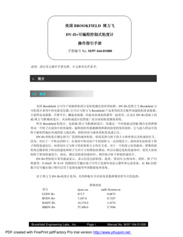
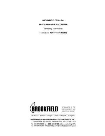
The equivalent units of measurement in the SI system are calculated using the followingconversions:Viscosity:Shear Stress:Torque:SICGS1 mPa s 1 cP1 Newton/m2 10 dyne/cm21 Newton/m 107 dyne/cmReferences to viscosity throughout this manual are done in CGS units. The DV-II ProViscometer provides equivalent information in SI units.I.1 ComponentsPlease check to be sure that you have received all components, and that there is no damage. Ifyou are missing any parts, please notify Brookfield Engineering or your local Brookfield agentimmediately. Any shipping damage must be reported to the carrier.ComponentDV-II Pro ViscometerModel S Laboratory StandSpindle Set with CaseLVDV-II Pro set of four spindlesRVDV-II Pro set of six spindles (#2 - #7)HA/HBDV-II Pro set of six spindles (#2 - #7)Part NumberQuantityvaries1MODEL S1variesSSLSSRSSH1ororFor Cone/Plate versions: a spindle wrench, one cone spindle and sample cup,Part No. CPE-44Y replace the spindle set.Power CordDVP-65 for 115 orDVP-66 for 230DVP-65DVP-66RTD Temperature ProbeDVP-94YGuard Leg:LVDV-II ProRVDV-II ProB-20YB-21YCarrying CaseDVLOADER CD ROMCable (DV-II Pro to computer)Operating ManualBrookfield Engineering Labs., Inc.Page 111DVE-7Y1DVLOADER1DVP-801M/03-1651Manual No. M/03-165-C0508C0808
COMPONENT DIAGRAMDV-II ProViscometerModel SLaboratory StandSpindle SetShippingCapGuard LegLV Spindle Setshown aboveTemperature Probe OptionCone/Plate OptionWrenchTemperature Probe ClipCone SpindleSample CupBrookfield Engineering Labs., Inc.Temperature ProbePage Manual No. M/03-165-C0508C0808
I.2 UtilitiesInput Voltage:Input Frequency:Power Consumption:Power Cord Color Code:Hot (live)NeutralGround (earth)115 VAC or 230 VAC50/60 Hz30 VAUnited StatesOutside United StatesBlackWhiteGreenBrownBlueGreen/YellowMain supply voltage fluctuations are not to exceed 10% of the nominal supply l (PC Control)Interleaved:Sequential:Custom:LV/RV (18 speeds)LV/RV (18 speeds)54 speeds, user selectable.01 - 200 rpm0.01 rpm increments from 0.01 to 0.99 rpm0.1 rpm increments from 1.0 to 200 rpmNote: Refer to Appendix F for detailed list of all speeds.Weight:Gross WeightNet WeightCarton Volume23201.65lbs.lbs.cu. ft.10.5 kg.9 kg.0.05 m3Temperature Sensing Range:-100 C to 300 C (-148 F to 572 F)Analog Torque Output:0 - 1 Volt DC (0 - 100% Torque)Analog Temperature Output:0 - 3.75 Volts DC (-100 C to 275 C)RS232 Compatible Serial Port for use with an attached printer or PC.Centronics Compatible Parallel Port for use with an attached printer.Viscosity Accuracy: 1.0% of full scale rangeViscosity Repeatability: 0.2%Temperature Accuracy: 1 C -100 C to 149 C 2 C 150 C to 300 COperating Environment:0 C to 40 C temperature range (32 F to 104 F)20% - 80%R.H.: non-condensing atmosphereBrookfield Engineering Labs., Inc.Page Manual No. M/03-165-C0508C0808
Ball Bearing Option:If you ordered the ball bearing suspension system with your new instrument please notethe following:1) The ball bearing suspension in your Brookfield instrument is noted on the serial tagon the back of the head by the letter “B” after the mode.2) When attaching and detaching the spindle, it is not necessary to lift the couplingwhere the spindle connects to the instrument.3) The Oscillation Check explained in the Appendix under Fault Diagnosis andTroubleshooting does not pertain to this instrument.Electrical Certifications:Conforms to CE Standards for: Electromagnetic Compatibility (EMC), Low Voltage (LVD)and Safety Requirements for electrical equipment for measurement control and laboratoryuse.I.4InstallationNote: “IQ, OQ, PQ”, a guideline document for installation, operation and performancevalidation for your DV-II Pro digital viscometer can be downloaded from our web site www.brookfieldengineering.com.1) Assemble the Model S Laboratory Stand (refer to assembly instructions in Appendix H).2) Put the viscometer on the stand.3) Connect the RTD probe to the socket on the rear panel of the DV-II Pro.4) The Viscometer must be leveled. The level is adjusted using the two leveling screws onthe base. Adjust so that the bubble level on top of the DV-II Pro is centered within thecircle.Note: Check level periodically during use.5) Remove the white shipping cap which secures lower coupling nut on Viscometer to pivotcup.6) Make sure that the AC power switch at the rear of the DV-II Pro is in the OFF position.Connect the power cord to the socket on the back panel of the instrument and plug it intothe appropriate AC line.The AC input voltage and frequency must be within the appropriate range as shownon the nameplate of the viscometer.Note: The DV-II Pro must be earth grounded to ensure against electronic failure!!7) Turn the power switch to the ON position and allow to warm up for 10 minutes beforeperforming autozero.Brookfield Engineering Labs., Inc.Page Manual No. M/03-165-C0508C0808
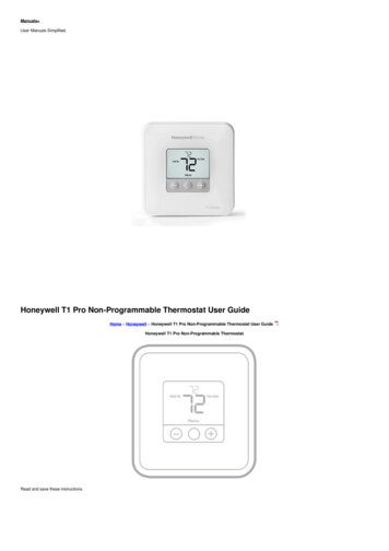
8) For Cone/Plate models, refer to Appendix A.9) If appropriate, connect interconnecting cable (DVP-80) to serial port for connection ofDV-II Pro to PC or printer.10) If appropriate, connect interconnecting cable to parallel port for connection of DV-II Proto printer.11) If appropriate, connect interconnecting cable (DVP-96Y) to analog (serial) port for connection of DV-II Pro to chart recorder.I.5Safety Symbols and PrecautionsSafety SymbolsThe following explains safety symbols which may be found in this operating manual.Indicates hazardous voltages may be present.Refer to the manual for specific warning orcaution information to avoid personal injuryor damage to the instrument.PrecautionsIf this instrument is used in a manner notspecified by the manufacturer, the protectionprovided by the instrument may be impaired.This instrument is not intended for use in apotentially hazardous environment.In case of emergency, turn off the instrumentand then disconnect the electrical cord from thewall outlet.BROOKFIELDVISCOMETERDV-II TERTABAUTORANGEôö §SELECTSPINDLEPRINTThe user should ensure that the substancesplaced under test do not release poisonous, toxicor flammable gases at the temperatures whichthey are subjected to during the testing.I.6Key FunctionsFigure I-1Figure I-1 shows the control keys on the face of the DV-II Pro Viscometer. The followingdescribes the function of each key. UP ARROWThis key is used to scroll UP (in an increasing value direction) through the availablespeed, spindle and Option menu tables.Brookfield Engineering Labs., Inc.Page Manual No. M/03-165-C0508C0808
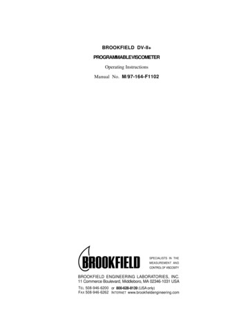
ANGESELECTSPINDLEThis key is used to scroll DOWN (in a decreasing value direction) through theavailable speed, spindle and option menu tables.MOTOR ON/OFF/ESCAPETurns the motor ON or OFF. ESCAPE exits the Options menu.SET SPEEDCauses the DV-II Pro to begin running at the currently selected speed. This functionworks only when the motor is ON. Also used to select custom speeds when in theCustom Speed option.SELECT DISPLAYSelects the data parameter to be displayed:cPViscosity (cP or mPa.s)SSShear Stress (dynes/cm2 or Newtons/m2)SRShear Rate (1/sec)ENTER/AUTO RANGEUsed to execute the currently flashing option.Presents the maximum (100% torque) viscosity attainable using theselected spindle at the current viscometer spindle speed.ENTER:AUTO RANGE:SELECT SPINDLEInitiates spindle selection on the first press and then selects the currently scrolled-tospindle when pressed a second time.PRINTTABPRINTSelects printing and non-printing modes when a printer is attached.OPTIONDOWN ARROWFOPTIONS/TABOPTIONS:TAB:Presents the Options menu, flashing the last escaped option.Toggles between selectable items when indicated, as shown inFigure 2.Note: Symbol indicatingthe OPTIONS/TAB keyfgfg F(FAHRENHEIT)CGS UNITS #Figure I-2Note:Inverted text (black background with white lettering) indicates that theinformation is flashing on the viscometer display.Brookfield Engineering Labs., Inc.Page 10Manual No. M/03-165-C0508C0808
I.7 CleaningBe sure to remove the spindle from the instrument prior to cleaning. Severe instrumentdamage may result if the spindle is cleaned in place.Instrument and Keypad:Clean with a dry, non-abrasive cloth. Do not use solventsor cleaners.Immersed Components (spindles):Spindles are made of stainless steel. Clean with a nonabrasive cloth and solvent appropriate for sample material.Note: When cleaning, take care not to apply excessive force - it may bend the spindles.Brookfield Engineering Labs., Inc.Page 11Manual No. M/03-165-C0508C0808
II. GETTING STARTEDII.1 AutozeroBefore readings may be taken, the Viscometer must be Autozeroed. This action is performedeach time the power switch is turned on. (Note: If cable DVP-80 is connected for printer orcomputer communication see section II.9.) The display window on the Viscometer will guideyou through the procedure as follows:Turn the power switch (located on the rear panel) to the ON position. This will result inthe screen display shown in Figure II-1 indicating that the DV-II Pro viscometer is in thestandalone mode (is not connected to a computer).BROOKFIELDPRODV-2 VISCOMETERFigure II-1After a few seconds, the following screen appears indicating the version of the operatingfirmware (the built in program which controls the instrument) and a two-digit alphanumericcode which indicates the Model number (see Table D2 in Appendix D; the code tells the springtorque rating or the viscosity measurement range of your viscometer). For most DV-II ProViscometers, this information will be either “LV”, “RV” or “HB”:BROOKFIELDRVDV-2 V6.3Figure II-2No key press is required at this point. After a short time, the display will clear and thefollowing will be displayed:REMOVE SPINDLEPRESS ANY KEYFigure II-3After removing the spindle and pressing any key, the DV-II Pro begins its Autozero. Thescreen will flash “Autozeroing.”After approximately 15 seconds, the display shows the screen in Figure II-4:REPLACE SPINDLEPRESS ANY KEYFigure II-4Brookfield Engineering Labs., Inc.Page 12Manual No. M/03-165-C0508C0808
Pressing any key at this point results in the display of the DV-II Pro default screen:CP 0.0OFFRPM20.1C% 0.0Figure II-5The display will vary depending upon the selection of temperature ( F or C) and units of viscosity(cP or mPa s).II.2SELECTSPINDLESpindle SelectionLVDV-II Pro Viscometers are provided with a set of four spindles and a narrow guardleg; RVDVII Pro Viscometers come with a set of six spindles and a wider guardleg; HADV-II Pro and HBDVII Pro Viscometers come with a set of six spindles and no guardleg. (See Appendix E for moreinformation on the guardleg.)The spindles are attached to the viscometer by screwing them onto the lower shaft. Note that thespindles have a left-hand thread. The lower shaft should be secured and slightly lifted with onehand while screwing the spindle to the left. The face of the spindle nut and the matching surfaceon the lower shaft should be smooth and clean to prevent eccentric rotation of the spindle. Spindlescan be identified by the number on the side of the spindle coupling nut.The DV-II Pro must have a Spindle Entry Code number to calculate Viscosity, Shear Rate and ShearStress values. The DV-II Pro memory contains parameters for all standard Brookfield spindlesincluding custom spindles and the two digit entry code for each spindle (the complete list of entrycodes may be found in Appendix D).Note:The DV-II Pro will remember the Spindle Entry Code which was in use when thepower was turned off.Pressing the SELECT SPINDLE key will display the current selected spindle code instead of temperatureand cause the character S to begin to blink . It will blink for about three seconds. If the UP or DOWNARROW keys are pressed (while S is blinking) the two character spindle value to the right of theS character will begin to change (in either an increasing or decreasing direction depending uponwhich ARROW key is pressed) for each press of the key. If the ARROW key is pressed and held, thedisplay will scroll through the spindle codes for as long as the ARROW key is depressed. When itreaches the last item in the list (either at the top or bottom of the list) the spindle code displayedwill “roll-over” to either the first or last spindle code and the scroll action will continue.When the desired spindle code is displayed, release the ARROW key to halt further scrolling. Pressthe SELECT SPINDLE key once again. This will cause the S character to cease blinking and the newspindle code will be accepted for use in viscometer calculations.Note:You have approximately three seconds in which to press the SELECT SPINDLE keybefore the blinking stops. If you fail to press the SELECT SPINDLE key before theblinking stops you will have to repeat the above steps and re-select the desiredspindle.Brookfield Engineering Labs., Inc.Page 13Manual No. M/03-165-C0508C0808
The DV-II Pro will begin to calculate using the new spindle parameters as soon as the SELECTSPINDLE key is pressed the second time.Note: The number 99 spindle is for use with special spindles when using Brookfield’sRHEOCALC32 computer program. Refer to the RHEOCALC32 operator manual forfurther information on using “99” spindles.The DV-II Pro may also be programmed at Brookfield Engineering for “special” user spindles.These “special” spindles will appear on the spindle scroll list starting with designation “AA”and continuing through “AZ”. Contact Brookfield Engineering regarding your needs for specialspindles.II.3SETSPEEDSpeed Selection, Setting, RunningThere are 54 speeds programmed into the DV-II Pro. These speeds correspond to the standardLVT, RVT, HAT and HBT dial models (18 possible speeds altogether) plus 36 additional speeds.The DV-II Pro comes with the Sequential Speed Set already selected (see Appendix F). The speedset will start at speed 0.0. It will then scroll up through the LV speeds, pass through speed 0.0 again,and then scroll up through the RV speeds, pass through speed 0.0 again and then repeat the abovesequence.The DV-II Pro can also be configured by the operator to interleave the LV and RV speeds. SeeSection III.2.3 on Setup for a description of how to install the Interleave Speed Set.A complete list of speed sets and custom speeds is included in Appendix F. The DV-II Pro can beprogrammed to select up to 19 of the 54 speeds for use at any one time. Speed 0.0 is the 20th speedand is automatically included. See Section III. 2.3.2 on Setup for a description of how to install aCustom Speed Set.To select a Viscometer speed first press either the UP or DOWN arrow keys which will cause the areato the right of RPM to display the currently selected speed. Figure II-6 shows the DV-II Pro isoperating at 6.0 RPM, and the current selected speed is 6.0 RPM.CP 123.46.0RPM6.0%20.1C15.6Figure II-6If the ARROW key is pressed just once and then released, the characters “RPM” will blink for threeseconds, then will cease blinking resulting in no change to the speed entry.Note: The speed selection process remembers the last value of scrolled-to speed so that thenext time you initiate a speed change (by pressing an ARROW key), the DV-II Pro willbegin its scroll display from the last entered value.The last-scrolled-to speed does not necessarily have to be the same as the speed at which the DVBrookfield Engineering Labs., Inc.Page 14Manual No. M/03-165-C0508C0808
II Pro is currently running. The user may operate at a given speed and pre-set the DV-II Pro tothe next desired speed before that speed will be used. For example, if the DV-II Pro is currentlyrunning at 6.0 RPM and was previously scrolled to 12 RPM, a single press of either ARROW keywould result in the Figure II-7 screen display:cP 123.46.0RPM1220.1C15.6%Figure II-7Pressing the SET SPEED key would cause the DV-II Pro to begin running at 12 RPM.If the user did not press the SET SPEED key, the DV-II Pro would continue to run at its current speedof 6 RPM. In fact, you may scroll to a new speed (12 RPM in this example) and press the SET SPEEDkey at any future time (without further pressing an ARROW key) to immediately cause the DV-II Proto run at the new speed. Pressing the ARROW
Brookfield Engineering Labs., Inc. Page 4 Manual No. M/03- 65-C0508 C0808 I. INTRODUCTION The Brookfield DV-II Pro Viscometer measures fluid viscosity at given shear rates.Viscosity is a measure of a fluid's resistance to flow.