Transcription
BROOKFIELD DIGITAL VISCOMETERMODEL DV-EOperating InstructionsManual No. M/98-350-G0307SPECIALISTS IN THEMEASUREMENT ANDCONTROL OF VISCOSITYwith offices in:Boston Chicago London Stuttgart GuangzhouBROOKFIELD ENGINEERING LABORATORIES, INC.11 Commerce Boulevard, Middleboro, MA 02346 USATEL 508-946-6200 or 800-628-8139 (USA excluding MA)FAX 508-946-6262 INTERNET http://www.brookfieldengineering.comBrookfield Engineering Labs., Inc.Page Manual No. M/98-350-G0307
TABLE OF CONTENTSI. lities.5Specifications.5Set-Up.5Safety Symbols and Precautions.6Instrument Controls.7Cleaning.8II. GETTING STARTED.9II.1II.2II.3II.4II.5Power Up.9Spindle Selection.9Speed Selection & Setting.10Autorange and CGS or SI Units Selection.11Out of Range .12II.6 Operation.13Appendix A - Viscosity Ranges.14Appendix B - Variables in Viscosity Measurement.17Appendix C - Spindle and Model Codes.19Appendix D - Calibration Procedures.21Appendix E - Model A Laboratory Stand with Parts Identification.26Appendix F - The Brookfield Guardleg.28Appendix G - Fault Diagnosis and Troubleshooting.30Appendix H - Warranty Repair and Service.31Brookfield Engineering Labs., Inc.Page Manual No. M/98-350-G0307
I. INTRODUCTIONThe Brookfield DV-E Viscometer measures fluid viscosity at given shear rates. Viscosity is ameasure of a fluid’s resistance to flow. You will find a detailed description of the mathematicsof viscosity in the Brookfield publication “More Solutions to Sticky Problems” a copy of whichwas included with your DV-E and can be downloaded in pdf form from the Brookfield website,www.brookfieldengineering.com.The principle of operation of the DV-E is to rotate a spindle (which is immersed in the test fluid)through a calibrated spring. The viscous drag of the fluid against the spindle is measured by thespring deflection. Spring deflection is measured with a rotary transducer which provides a torquesignal. The measurement range of a DV-E (in centipoise or milliPascal seconds) is determinedby the rotational speed of the spindle, the size and shape of the spindle, the container in which thespindle is rotating, and the full scale torque of the calibrated spring.There are four basic spring torque series offered by Brookfield:ModelLVDV-ERVDV-EHADV-EHBDV-ESpring Torquedyne-cm milli 96.05.7496The higher the spring torque, the higher the measurement range. The viscosity measurement rangefor each spring torque may be found in Appendix A.All units of measurement are displayed according to either the CGS (cP) system or the SI(mPa s) system.1. Viscosity appears in units of centipoise (shown as “cP”) or milliPascal-seconds (shownas “mPa s”) on the DV-E display.2. Torque appears in units of dyne-centimeters or Newton-meters (shown as percent “%”in both cases) on the DV-E display.The equivalent units of measurement in the SI system are calculated using the following conversions:SICGS1 mPa s 1 cPViscosity:Torque:1 Newton-m 107 dyne-cmReferences to viscosity throughout this manual are made in CGS units. The DV-E Viscometerprovides equivalent information in SI units (see Section II.4 AUTORANGE).I.1 ComponentsPlease check to be sure that you have received all components, and that there is no damage. Ifyou are missing any parts, please notify Brookfield Engineering or your local Brookfield agentimmediately. Any shipping damage must be reported to the carrier.Brookfield Engineering Labs., Inc.Page Manual No. M/98-350-G0307
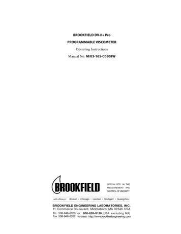
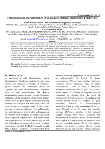
ComponentDV-E ViscometerModel A laboratory standSpindle Set with Case:LVDV-E set of four spindlesRVDV-E set of six spindles (#2-#7)HA/HBDV-E set of six spindles (#2-#7)Power Cord:for 115 VACfor 230 VACGuard Leg:LVDV-ERVDV-ECarrying CaseShipping CapPart NumbervariesModel AKQuantity11SSLSSRSSH1 or1 or1DVP-65DVP-6611orB-20YB-21Y001YB-30-31 or111DV-EViscometerModel ALaboratory StandShippingCapGuard LegFigure I-1Brookfield Engineering Labs., Inc.Page Manual No. M/98-350-G0307
I.2 UtilitiesInput Voltage:Input Frequency:Power Consumption:115 VAC or 230 VAC50/60 HzLess than 20 WATTSPower Cord Color Code:Hot (live)NeutralGround (earth)United StatesBlackWhiteGreenOutside United StatesBrownBlueGreen/YellowI.3 SpecificationsSpeeds:Weight:0.3, 0.5, 0.6, 1.0, 1.5, 2.0, 2.5, 3.0, 4.0, 5.0, 6.0, 10, 12, 20, 30, 50, 60, 100 RPMGross Weight20 lb9 kgNet Weight17 lb7.7 kgCarton Volume1.65 cu ft0.05 m3Carton Dimension19 x 10 x 15 in48 x 25 x 38 cmOperating Environment:Accuracy:0 C to 40 C Temperature Range (32 F to 104 F)20% - 80% R.H.: non-condensing atmosphere 1.0% Full Scale Range in Use (See Appendix D for details)Reproducibility: 0.2% of Full Scale RangeElectrical Certifications:Conforms to CE Standards: BSEN 50081-1: Emission Standard - Light IndustrialBSEN 50082-1: Immunity Standard - Light IndustrialBSEN 50081-2: Emission Standard - IndustrialBSEN 50082-2: Immunity Standard - IndustrialBSEN 61010-1: Safety requirements for electricalequipment, for measurement, controland laboratory useApproved Standards:CSA Std. C22.2 No. 151-M1986 - Laboratory EquipmentCSA Class 8721 81 - Laboratory EquipmentThis product has been certified to the applicable CSA and ANSI/UL Standards, for usein Canada and the U.S.I.4 Set-Up1.To assemble the Model A Laboratory Stand, place the upright rod into the base (refer toassembly instructions in Appendix E).2.Insert the mounting rod on the back of the DV-E Viscometer into the hole on the clampassembly. (Refer to Appendix E).3.The Viscometer must be leveled. The level is adjusted using the three leveling screws onthe base. Adjust so that the bubble level on top of the DV-E is centered within the circle.Note: Check level periodically during use.Brookfield Engineering Labs., Inc.Page Manual No. M/98-350-G0307
4.Remove the Viscometer shipping cap from the pivot cup. This cap is designed to protectthe Viscometer spindle coupling nut during shipment. Do not attempt to operate the Viscometer with the shipping cap in place! Save this cap for future use.5.Make sure that the power switch at the rear of the DV-E is in the OFF (0) position. Connect the power cord to the socket on the back panel of the instrument and plug it into theappropriate AC power line.The AC input voltage and frequency must be within the appropriate range as shown onthe name plate of the viscometer.The DV-E must be earth grounded to ensure against electronic failure!!I.5 Safety Symbols and PrecautionsSafety SymbolsThe following explains safety symbols which may be found in this operating manual.Indicates hazardous voltages may be present.Refer to the manual for specific warning or caution information to avoid personal injury or damage to the instrument.PrecautionsIf this instrument is used in a manner not specified by the manufacturer, the protectionprovided by the instrument may be impaired.This instrument is not intended for use in a potentially hazardous environment.In case of emergency, turn off the instrument and then disconnect the electrical cord fromthe wall outletThe user should ensure that the substances placed under test do not release poisonous,toxic or flammable gases at the temperatures to which they are subjected to during thetesting.Brookfield Engineering Labs., Inc.Page Manual No. M/98-350-G0307
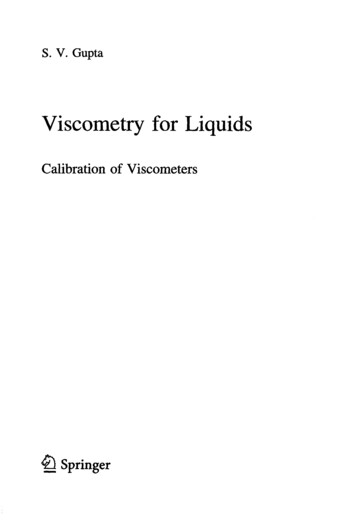
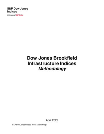
I.6 Instrument ControlsThe following describes each switch’s function:Figure I-2MOTOR ONTurns the motor ON or OFF.AUTO RANGEPresents the maximum (100% torque) viscosity attainable using the selected spindle at the selectedspeed. This value is referred to as full scale range. The allowable error for the viscosity measurement is 1% of full scale range.Note: Pressing and holding the Auto Range key during power on will enable the viscosity display to be read in either CGS (cP) or SI (mPa s) units.Brookfield Engineering Labs., Inc.Page Manual No. M/98-350-G0307
SPEED/SPINDLE SWITCHSets the viscometer in either speed select or spindle select (see Table C1 in Appendix C) mode.When set in the left position, the operator may select speed of rotation. When set in the right position, the operator may select spindle.Note: This is a three (3) position switch. We recommend that the switch be set to themiddle position when finished with spindle or speed adjustment. This will prevent anaccidental change of parameters during a test.SELECT KNOBThis knob is used to scroll through the available speed or spindle selections (see Table C1 in Appendix C). This knob is active when the switch is set to the left (speed) or right (spindle) position.Rotate the knob clockwise to increase value and counter-clockwise to decrease value.I.7 CleaningBe sure to remove spindle from instrument prior to cleaning. Note that thespindles and coupling have a left-hand thread. Severe instrument damage mayresult if cleaned in place.Instrument and Keypad:Clean with dry, non-abrasive cloth. Do not use solventsor cleaners.Immersed Components (spindles):Spindles are made of stainless steel. Clean with nonabrasive cloth and solvent appropriate for sample materialthat is not aggressive to immersed components.When cleaning, do not apply excessive force which may result in bending spindles.Brookfield Engineering Labs., Inc.Page Manual No. M/98-350-G0307
II. GETTING STARTEDII.1 Power UpTurn the power switch (located on the rear panel) to the ON (I) position. This will result in thefollowing screen display:BROOKFIELDDV-ERVVISCOMETERFigure II-1After a few seconds, the following screen appears:BROOKFIELDVERSION:DV-E1.00Figure II-2After a short time, the display will clear and the default screen is displayed:cP10OFF %S02Figure II-3II.2 Spindle SelectionLVDV-E Viscometers are provided with a set of four spindles and a narrow guardleg; RVDV-EViscometers come with a set of six spindles and a “wider” guardleg; HADV-E and HBDV-E Viscometers come with a set of six spindles and no guardleg. (See Appendix D for more informationon the guardleg.)The spindles are attached to the viscometer by screwing them to the male coupling nut. Note thatthe spindles and coupling have a left-hand thread. The lower shaft should be held in one hand(lifted slightly), and the spindle screwed to the left. The face of the spindle nut and the matchingsurface on the coupling nut shaft should be smooth and clean to prevent eccentric rotation of thespindle. Spindles can be identified by the number on the side of the spindle coupling nut.The DV-E must have a Spindle Entry Code number to calculate viscosity values. The DV-Ememory contains parameters for all standard Brookfield spindles and the two digit entry code foreach spindle (the complete list of spindle entry codes may be found in Appendix C).Note: The DV-E will display the Spindle Entry Code which was in use when power wasturned off.Setting the SPEED/SPINDLE switch to the right position will allow the operator to adjust thespindle selection. The SELECT knob can be rotated until the desired spindle number is selected.Once the desired spindle number is shown on the display, set the SPINDLE/SPEED switch to themiddle position.Brookfield Engineering Labs., Inc.Page Manual No. M/98-350-G0307
Note: Verify the proper spindle entry code for the selected spindle found in Appendix C.Not all spindles have an entry code number that is the same as the spindle number.For example: the spindle entry code for spindle LV1 is 61 and the spindle entry codefor UL Adapter is 00.The DV-E will begin to calculate using the new spindle parameters after the spindle number isshown in the display.Please see Brookfield publication, “More Solutions to Sticky Problems” (Chapter 3), for information on how to select a spindle.II.3 Speed Selection & SettingThere are 18 rotational speeds available on the DV-E Viscometer. These speeds correspond to thestandard LVF, LVT, RVF, RVT, HAT and HBT Dial Viscometers models and they are combinedsequentially. See Table 1 below.Table 1: DV-E 0100TableSetting the SPEED/SPINDLE switch in the left position will allow the operator to adjust the speedselection. The SELECT knob can be rotated until the desired speed is selected. Once the desiredspeed is shown on the display, set the SPINDLE/SPEED switch to the middle position.The viscometer will rotate the spindle at the selected speed when the motor switch is in the ONposition. A motor on condition is indicated on the display by RPM shown beside the speed. Whenthe motor switch is in the OFF position, OFF will be displayed beside the speed.cP12RPM %S02(MOTOR ON)Brookfield Engineering Labs., Inc.Page 10Manual No. M/98-350-G0307
cP12OFF %S02(MOTOR OFF)Figure II-4Note: When the motor switch is in the ON position, any change to the selected speed willbe effective immediately. When collecting data at multiple speeds, you may wish toleave the SPEED/SPINDLE switch in the left position to facilitate speed changes.Also, when the motor switch is turned off, the display will hold the last measuredtorque value and measured viscosity.The DV-E Viscometer employs an optical signal pick-up inside the instrument to detect the torquevalue of the calibrated spring. This optical signal pick-up is recorded four times per revolution ofthe spindle. When the spindle begins to rotate at a defined speed, four torque values are recordedduring the first full revolution of the spindle and averaged together. The display reports the averagevalue for both torque (%) and viscosity (cP or mPa s). Thereafter, the next torque value recordedby the optical signal pick-up is averaged together with the three preceding torque values and thenewly calculated torque (%) and viscosity (cP or mPa s) values are then displayed. This 4x revolution pick-up and display continues as long as the motor is on.This algorithm in the instrument firmware is used for all viscosity and torque readings. Consequently, the wait time to observe the initial displayed readings for torque and viscosity increase asyou go to lower speeds.It may also be necessary to allow time for the indicated reading to stabilize.Note: At speeds of 1 RPM and lower, additional time may be required to allow for complete deflection of the torque sensor. The % (torque) and cP (viscosity) will flashuntil 1 revolution is achieved and the % torque value is greater than 10%.The time required for stabilization will depend on the speed at which the Viscometer is runningand the characteristics of the sample fluid. For maximum accuracy, readings below 10% shouldbe avoided. Additional information on making viscosity measurements is available in Appendix Bor the Brookfield publication “More Solutions to Sticky Problems” .The DV-E Viscometer will remember the selected speed and spindle when power is turned off. Onstart-up, the Viscometer will be set to the previously selected spindle and speed.Please see Brookfield publication “More Solutions to Sticky Problems” (Chapter 3) for informationon how to select a speed.II.4 Autorange and CGS or SI Units SelectionThe AUTO RANGE key allows you to determine the maximum calculated viscosity (full scale reading) possible with the current spindle/speed setting. Pressing the key at any time will cause thecurrent viscosity display to change and show that maximum viscosity. The screen torque displaywill now display “%100” to indicate this special condition. This maximum viscosity and %100value will be displayed for as long as the AUTO RANGE key is depressed. Figure 5 shows theAUTO RANGE function for the situation where the No. 2 RV spindle is rotating at 10 RPM. TheBrookfield Engineering Labs., Inc.Page 11Manual No. M/98-350-G0307
full scale range is 4000 cP (or 4000 mPa.s).cP 400010RPM %100S02Figure II-5Pressing and holding the AUTO RANGE key during power on will enable the viscosity unit displayed to toggle between CGS (cP) and SI (mPa s) units. To change the unit format:1. Turn the power off.2. Press and hold the AUTO RANGE key and turn the power ON.The DV-E will retain the unit selection when the viscometer is turned OFF.CGSSIViscosity:cPmPa.s1 cP 1 mPa sII.5 Out of RangeThe DV-E gives indications for out of specification or out-of-range operation. When % (Torque)readings exceed 100.0 % (over-range), the display changes to that shown in Figure 6:cP EEEE10RPM %EEEES02Figure II-6You must either reduce speed or use a smaller size spindle to correct this condition. If you operateat spindle speeds that produce % (Torque) below 10.0 % (under-range), the DV-E displays both% (Torque) and cP (Viscosity) with flashing unit designations. You must either increase speed oruse a larger size spindle to correct this condition.The parameters of % (Torque) and cP (Viscosity) will also flash prior to one complete spindlerevolution. It is not recommended that readings are taken while parameters are flashing.cP 36010RPM % 9.0S02Figure II-7Negative % (Torque) will be displayed as shown in Figure II-8. Viscosity values will be displayedas “- - - -” when the % (Torque) is below zero.cP ---10RPM %-1.0S02Figure II-8Brookfield Engineering Labs., Inc.Page 12Manual No. M/98-350-G0307
II.6 OperationThe following procedure is outlined for making a viscosity measurement in the recommended 600mL low form Griffin beaker.1. Insert and center spindle in the test material until the fluid’s level is at the immersion groove onthe spindle’s shaft. With a disc-type spindle, it is sometimes necessary to tilt the spindle slightlywhile immersing to avoid trapping air bubbles on its under side surface. (Brookfield recommends that you immerse the spindle in this fashion before attaching it to the Viscometer.)2. Mount the guardleg on the DV-E Viscometer (LV and RV series). Be sure that the motor isOFF before attaching the spindle. Select a spindle and attach it to the spindle coupling nut.Lift the shaft slightly, holding it firmly with one hand while screwing the spindle on with theother (note left-hand thread). Avoid putting side thrust on the shaft.3. To make a viscosity measurement, select a speed and follow the instructions in Sections II.2 andII.3. Allow time for the indicated reading to stabilize. The time required for stabilization willdepend on the speed at which the Viscometer is running and the characteristics of the samplefluid. For maximum accuracy, flashing readings below 10% should be avoided. Additionalinformation on making viscosity measurements is available in Appendix B or the Brookfieldpublication “More Solutions to Sticky Problems”.4. Switch the MOTOR ON/OFF switch to turn the motor “OFF” when changing a spindle orchanging samples. Remove spindle before cleaning.5. Interpretation of results and the instrument’s use with non-Newtonian and thixotropic materialsis discussed in the booklet, “More Solutions to Sticky Problems”, and in Appendix B, Variablesin Viscosity Measurements.Brookfield Engineering Labs., Inc.Page 13Manual No. M/98-350-G0307
Appendix A - Viscosity RangesLV and RV,HA,HB ViscometersViscometerViscosity Range (cP)MinimumMaximumLVDV-E152MRVDV-E100*13 MHADV-E200*26 MHBDV-E800*106 M*Minimum viscosity with optional RV/HA/HB-1 spindleSmall Sample Adapter (SSA) and Thermosel (Tsel)SSA/ThermoselSpindleViscosity (cP)Shear Rate(1/SEC)LVDV-ESC4-16 (SSA)0.29 N120-400 KSC4-18 (SSA/Tsel)1.32 N3-10 KSC4-25 (SSA)0.22 N800-1.60 KSC4-31 (SSA/Tsel)0.34 N30-100 KSC4-34 (SSA/Tsel)0.28 N60-200 KHT-81 (Tsel)1.29 N3.5-10 KSC4-82 (SSA)1.29 N3.5-10 KSC4-83 (SSA)1.29 N11.0-38 KSSA/Thermosel SpindleShearRate(1/SEC)Viscosity (cP)RVDV-EHADV-EHBDV-ESC4-14 (SSA)0.40N1.25K-4.2 M2.5 M-8.3 M10 M-33.3 MSC4-15 (SSA)0.48N500-1.7 M1M-3.3 M4M-13.3 MSC4-21 (SSA/Tsel)0.93N50-170 K100-300 K400-1.3 MSC4-27 (SSA/Tsel)0.34N250-830 K500-1.7 M2M-6.7 MSC4-28 (SSA/Tsel)0.28N500-1.7 M1M-3.3 M4M-13.3 MSC4-29 (SSA/Tsel)0.25N1K-3.3 M2M-6.7 M8M-26.7 MHT-81 (Tsel)1.29N36-10 K73-10 K292-10 KSC4-82 (SSA)1.29N36-10 K73-10 K292-10 KSC4-83 (SSA)1.29N121-50 K242-50 K970-50 KcP CentipoiseBrookfield Engineering Labs., Inc.K 1,000M 1,000,000Page 14N RPMManual No. M/98-350-G0307
UL AdapterViscosity (cP)UL SpindleShear Rate(1/SEC)LVDV-ERVDV-EHADV-EHBDV-EYULA-15 or 15Z1.224N1.0 - 2 K6.4 - 2 K12.8 - 2 K51.2 - 2 KDIN Adapter AccessoryViscosity (cP)DAA SpindleShear Rate(1/SEC)851.29N1.2-3.8 K12-5K24-5K98-5K861.29N3-10 K36-10 K73-10 K292-10 K871.29N11-38 K12-50 K242-50 K970-50 KLVDV-ERVDV-EHADV-EHBDV-ESpiral AdapterViscosity (cP)DAA SpindleShear Rate(1/SEC)LVDV-ERVDV-EHADV-EHBDV-ESA-700.68 - 68100 - 98 K1M-1M2M-2M8 M - 8.4 M(1-100 RPM)Helipath with T-Bar SpindlesT-BarSpindleT-ALVDV-E156RVDV-E-62 KViscosity (cP)2M-400 KHADV-EHBDV-E4M-800 K16 M-3.2 MT-B312-124 K4M-800 K8M-1.6 M32 M-6.4 MT-C780-312 K10 M-2M20 M-4M80 M-16 MT-D1.5 M-624 K20 M-4M40 M-8M160 M-32 MT-E3.9 M-1.5 M50 M-10 M100 M-20 M400 M-80 MT-F7.8 M-3.1 M100 M-20 M200 M-40 M800 M-160 McP CentipoiseK 1,000M 1,000,000N RPMIn taking viscosity measurements with the DV-E Viscometer, there are two considerations whichpertain to the low viscosity limit of effective measurement.Brookfield Engineering Labs., Inc.Page 15Manual No. M/98-350-G0307
1)Viscosity measurements should be accepted within the equivalent % Torque Range from10% to 100% for any combination of spindle/speed rotation.2)Viscosity measurements should be taken under laminar flow conditions, not under turbulentflow conditions.The first consideration has to do with the accuracy of the instrument. All DV-E Viscometers have afull scale range accuracy of ( /-) 1% of any spindle/speed rotation. We discourage taking readingsbelow 10% of range because the potential viscosity error of ( /-) 1% is a relatively high numbercompared to the instrument reading.The second consideration involves the mechanics of fluid flow. All rheological measurements offluid flow properties should be made under laminar flow conditions. Laminar flow is flow whereinall particle movement is in layers directed by the shearing force. For rotational systems, this meansall fluid movement must be circumferential. When the inertial forces on the fluid become too great,the fluid can break into turbulent flow wherein the movement of fluid particles becomes randomand the flow can not be analyzed with standard math models. This turbulence creates a falsely highviscometer reading with the degree of non-linear increase in reading being directly related to thedegree of turbulence in the fluid.For the following geometries, we have found that an approximate transition point to turbulent flowoccurs:1)2)3)No. 1 LV (optional) Spindle:No. 1 RV (optional) Spindle:UL Adapter:15 cP at 60 RPM100 cP at 20 RPM0.85 cP at 60 RPMTurbulent conditions will exist in these situations whenever the RPM/cP ratio exceeds the valueslisted above.Brookfield Engineering Labs., Inc.Page 16Manual No. M/98-350-G0307
Appendix B - Variables in Viscosity MeasurementAs with any instrument measurement, there are variables that can affect a viscometer measurement.These variables may be related to the instrument (viscometer), or the test fluid. Variables relatedto the test fluid deal with the rheological properties of the fluid, while instrument variables wouldinclude the viscometer design and the spindle geometry system utilized.Rheological PropertiesFluids have different rheological characteristics that can be described by viscometer measurements.We can then work with these fluids to suit the lab or process conditions.There are two categories of fluids:-These fluids have the same viscosity at different Shear Rates (differentRPM’s) and are called Newtonian over the Shear Rate range they aremeasured.Non-Newtonian -These fluids have different viscosities at different shear rates (differentRPM’s). They fall into two groups:Newtonian1) Time Independent2) Time DependentTime Independent means that the viscosity behavior does not change as a function of time whenmeasuring at a specific shear rate.Pseudoplastic-A pseudoplastic material displays a decrease in viscosity with an increasein shear rate, and is also known as “shear thinning”. If you take viscometer readings from a low to a high RPM and then back to the low RPM,and the readings fall upon themselves, the material is time independentpseudoplastic and shear thinning.Time Dependent means that the viscosity behavior changes as a function of time when measuring at a specific shear rate.Thixotropic-A thixotropic material has decreasing viscosity under constant shear rate.If you set a viscometer at a constant speed recording viscosity values overtime and find that the viscosity values decrease with time, the material isthixotropic.Brookfield publication, “More Solutions to Sticky Problems”, includes a more detailed discussionof rheological properties and non-Newtonian behavior.Viscometer Related VariablesMost fluid viscosities are found to be non-Newtonian. They are dependent on Shear Rate and thespindle geometry conditions. The specifications of the viscometer spindle and chamber geometrywill affect the viscosity readings. If one reading is taken at 2.5 rpm, and a second at 50 rpm, thetwo viscosity values produced will be different because the readings were made at different shearrates. The faster the spindle speed, the higher the shear rate.Brookfield Engineering Labs., Inc.Page 17Manual No. M/98-350-G0307
The shear rate of a given measurement is determined by: the rotational speed of the spindle, thesize and shape of the spindle, the size and shape of the container used and therefore, the distancebetween the container wall and the spindle surface.A repeatable viscosity test should control or specify the following:1)2)3)4)5)6)7)Test temperatureSample container size (or spindle/chamber geometry)Sample volumeViscometer modelSpindle used (if using LVDV-E (#1-4) or RVDV-E (#2-7) attach the guard leg)Test speed or speeds (or the shear rate)Length of time or number of spindle revolutions to record viscosity.Brookfield Engineering Labs., Inc.Page 18Manual No. M/98-350-G0307
Appendix C - Spindle and Model CodesEach spindle has a two digit code which is scrolled via the select knob on the DV-E. The spindlecode directs the DV-E to calculate viscosity for the spindle that is being used. The spindle multiplierconstant (SMC) is used to calculate full scale viscosity range for any spindle/speed combination.Spindle codes are listed in Table C-1.SPINDLECODESPINDLESMCCODESMC01{RV1 RV606100T-B924007{RV707400T-C93100H01{HA1 3.75H01{HB1 27272565{LV5 {LV3C67128SC4-313132SA -70 {Spiral70105SC4-343464V-71712.62Table C-1Brookfield Engineering Labs., Inc.Page 19Manual No. M/98-350-G0307
VISCOMETERMODELTORQUE CONSTANTTKMODEL CODEON DV-E ECIAL ORDER TORQUE SPRINGSVISCOMETERMODELTORQUE CONSTANTTKMODEL CODEON DV-E SCREEN2.5xLVDV-E0.23432.5LV5xLVDV-E0.46865LV1/4 RVDV-E0.251/4RV1/2 162HB2.5xHBDV-E202.5HB5xHBDV-E405HBTable C-2This equation can be used to calculate the maximum viscosity that can be measured when using aspecific speed/spindle combination.Full Scale Viscosity Range (FSR) TK * SMC * 10,000RPMThe units for FSR are in centipoise (cP). An example is shown in Appendix D.Brookfield Engineering Labs., Inc.Page 20Manual No. M/98-350
Brookfield Engineering Labs., Inc. Page 9 Manual No. M/98-350-G0307 II. GETTING STARTED II. Power Up Turn the power switch (located on the rear panel) to the ON (I) position. This will result in the following screen display: BROOKFIELD DV-E RV VISCOMETER Figure II-1 After a few seconds, the following screen appears: BROOKFIELD DV-E VERSION: 1.00