Transcription
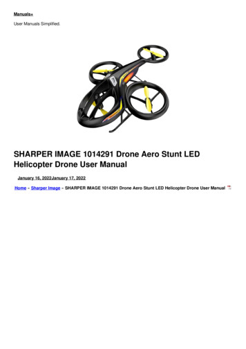
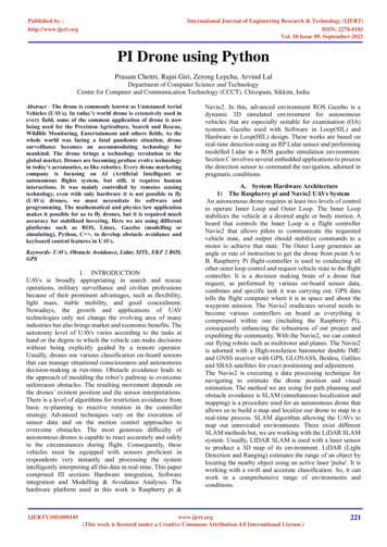
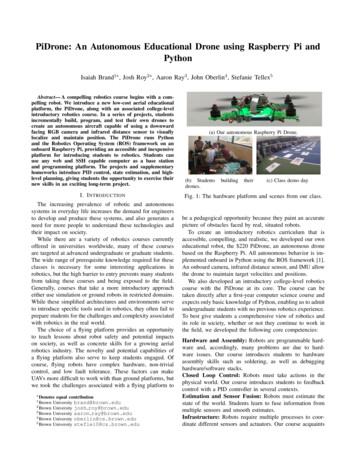
PiDrone: An Autonomous Educational Drone using Raspberry Pi andPythonIsaiah Brand1 , Josh Roy2 , Aaron Ray3 , John Oberlin4 , Stefanie Tellex5Abstract— A compelling robotics course begins with a compelling robot. We introduce a new low-cost aerial educationalplatform, the PiDrone, along with an associated college-levelintroductory robotics course. In a series of projects, studentsincrementally build, program, and test their own drones tocreate an autonomous aircraft capable of using a downwardfacing RGB camera and infrared distance sensor to visuallylocalize and maintain position. The PiDrone runs Pythonand the Robotics Operating System (ROS) framework on anonboard Raspberry Pi, providing an accessible and inexpensiveplatform for introducing students to robotics. Students canuse any web and SSH capable computer as a base stationand programming platform. The projects and supplementaryhomeworks introduce PID control, state estimation, and highlevel planning, giving students the opportunity to exercise theirnew skills in an exciting long-term project.I. I NTRODUCTIONThe increasing prevalence of robotic and autonomoussystems in everyday life increases the demand for engineersto develop and produce these systems, and also generates aneed for more people to understand these technologies andtheir impact on society.While there are a variety of robotics courses currentlyoffered in universities worldwide, many of these coursesare targeted at advanced undergraduate or graduate students.The wide range of prerequisite knowledge required for theseclasses is necessary for some interesting applications inrobotics, but the high barrier to entry prevents many studentsfrom taking these courses and being exposed to the field.Generally, courses that take a more introductory approacheither use simulation or ground robots in restricted domains.While these simplified architectures and environments serveto introduce specific tools used in robotics, they often fail toprepare students for the challenges and complexity associatedwith robotics in the real world.The choice of a flying platform provides an opportunityto teach lessons about robot safety and potential impactson society, as well as concrete skills for a growing aerialrobotics industry. The novelty and potential capabilities ofa flying platform also serve to keep students engaged. Ofcourse, flying robots have complex hardware, non-trivialcontrol, and low fault tolerance. These factors can makeUAVs more difficult to work with than ground platforms, butwe took the challenges associated with a flying platform to Denotes1 Brown2 Brown3 Brown4 Brown5 Brownequal contributionUniversity brand@brown.eduUniversity josh roy@brown.eduUniversity aaron ray@brown.eduUniversity oberlin@cs.brown.eduUniversity stefie10@cs.brown.edu(a) Our autonomous Raspberry Pi Drone.(b) Studentsdrones.buildingtheir(c) Class demo dayFig. 1: The hardware platform and scenes from our class.be a pedagogical opportunity because they paint an accuratepicture of obstacles faced by real, situated robots.To create an introductory robotics curriculum that isaccessible, compelling, and realistic, we developed our owneducational robot, the 220 PiDrone, an autonomous dronebased on the Raspberry Pi. All autonomous behavior is implemented onboard in Python using the ROS framework [1].An onboard camera, infrared distance sensor, and IMU allowthe drone to maintain target velocities and positions.We also developed an introductory college-level roboticscourse with the PiDrone at its core. The course can betaken directly after a first-year computer science course andexpects only basic knowledge of Python, enabling us to admitundergraduate students with no previous robotics experience.To best give students a comprehensive view of robotics andits role in society, whether or not they continue to work inthe field, we developed the following core competencies:Hardware and Assembly: Robots are programmable hardware and, accordingly, many problems are due to hardware issues. Our course introduces students to hardwareassembly skills such as soldering, as well as debugginghardware/software stacks.Closed Loop Control: Robots must take actions in thephysical world. Our course introduces students to feedbackcontrol with a PID controller in several contexts.Estimation and Sensor Fusion: Robots must estimate thestate of the world. Students learn to fuse information frommultiple sensors and smooth estimates.Infrastructure: Robots require multiple processes to coordinate different sensors and actuators. Our course acquaints
II. R ELATED W ORKThe PiDrone and class have some similarities to existingcourses and robotic platforms but fill a gap in availableintroductory-level robotics courses and extensible drone platforms for education.MIT’s Feedback Control Systems [2], offered by SertacKaraman, gives each student a Parrot Rolling Spider whichthey program and use to develop control systems. Karaman’sstudents develop advanced control algorithms using Matlaband Simulink which run onboard the Rolling Spider usinga custom firmware. Our use of the Raspberry Pi increasesthe computational power onboard, enabling us to presenta solution in Python and ROS, increasing accessibility.Additionally, our course includes an introduction to thehardware components of the drone, giving students a broadintroduction to robotics.Another drone-centric course, the Udacity Flying CarsNanodegree [3], aims to teach students about advancedconcepts in drone technology. It is an advanced course thatprepares students for work with unmanned aerial systems,while our course uses drones as an introduction to the wholefield of robotics. Additionally, Udacity’s course focuses onsimulation, with an optional physical extension, whereas aphysical robot is integral to our approach.MIT’s Duckietown class [4], [5] uses multiple autonomousRaspberry Pi ground robots to teach concepts in autonomousdriving. This course is more advanced than ours, providingan opportunity to study multi-robot interactions at a smallscale, but requires significantly more background in robotics.In addition, it uses a ground robot instead of an aerial robot.We considered several off-the-shelf drone platforms to usein the course. Table I demonstrates the differences betweenthe PiDrone and the other platforms we considered.The Parrot AR Drone [6] shares many capabilities with thePiDrone, but it does not officially allow users to program theonboard computer. Instead, the user sends commands to theexisting software with a phone or computer. For extensibleprogramming, students need a ROS-enabled base station,which is a significant burden when teaching a large class.By using ROS on-board the Raspberry Pi, we allow studentsto use any SSH and Javascript capable computer as a base1 ng SpiderParrot AR drone1Duckietown1 DiscontinuedROSProductOnboardPythonIn this paper we present the PiDrone and associatedintroductory robotics course, as well as an evaluation andcharacterization of the PiDrone’s flight and autonomouscapabilities. For a video overview of the course, please seethe video submission and a longer version on YouTube 1 .TABLE I: Low Cost Educational Robotic PlatformsCoststudents with message passing architectures using ROS [1],because it is an industry standard. We also emphasize networking, development workflow in Linux, and other fundamentals.Safety and Regulatory Concerns: Robots are potentiallydangerous tools. Our course teaches students to use thePiDrone safely and understand the complex regulatoryframework that surrounds unmanned aerial systems. 220 180 40 300 1504888444844448444488444448station, without reinstalling their OS. The Parrot AR Droneis also a discontinued product, so it is not feasible for ourcourse.The Crazyflie [7] is a tiny WiFi-enabled drone developedspecifically to support experimentation and modification. Theplatform is open-source and well documented and supportsadd-on boards that extend its capabilities. The Crazyflie hasbeen successfully used in a class at UC Berkeley [8]. Thoughthis aircraft was a contender our course because of it’ssmall size and open-source community, the limited computepower onboard, lack of support for ROS, and prebuilt natureof aircraft didn’t satisfy all of our goals for the class.Critically, at the time we were unable to find instances ofthe Crazyflie being used with an onboard camera (though anoptical flow add-on sensor has since become available forthe platform [9]).Picopter [10] has developed a similar platform to ours,but it is targeted at Makers and drone enthusiasts rather thanan educational robotics setting. It focuses on racing controlwith GPS localization rather than autonomy. Additionally,the Picopter is not currently available for sale, so it does notprovide a feasible platform for our course.After a survey of available systems, we concluded that ourgoals could best be met by developing our own educationalrobot. We wanted our drone to be approachable, extensible,ground up, and powerful — metrics we felt were not entirely satisfied by existing platforms. We think the resultingPiDrone fills a gap in the existing educational drones.III. ROBOT A RCHITECTUREThe PiDrone platform is designed to be inexpensive,robust, extensible, and autonomous. Components for theplatform are readily available online and are sourced almostentirely from HobbyKing.com. A complete parts list can befound on our course website [11].The aircraft is built around a durable, single-piece plasticframe. It uses 5 inch, 3-bladed props that were found tobe particularly resistant to shattering in crashes. We chosebrushless DC motors with reinforced shafts and bearingsthat proved much more resilient than many other motors wetested. This component adds significantly to the price, andin the future we plan to test alternatives in order to reducethe platform cost.
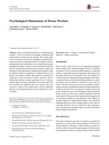
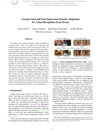
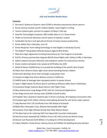
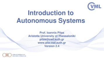
TABLE II: Parts ionicsSensorsSensorsPowerHardwareRaspberry PiSkyline324 Motors4 ESCsIR distance sensorPi CameraBattery and ChargerFrame and Hardware 35 15 60 40 20 15 30 5Total Cost 220The motors are driven by Afro 12 Amp optoisolatedelectronic speed controllers (ESCs) because they provedreliable in testing, and their power and signal indicator lightsare useful for students when debugging hardware problemswith their drones. The ESCs were reflashed with BLHelifirmware instead of the default SimonK firmware, as thenew firmware improved the response of the motors to rapidlychanging throttle inputs produced by the PID controller.Power for the system comes from a three-cell 1500milliamp-hour lithium polymer battery. Every student wasgiven three batteries and two chargers. With three batteries,students can fly almost continuously by charging their batteries in rotation, with a flight time of 7 minutes on onebattery.The low-level attitude control and the higher-level autonomy control run on two separate boards. The Skyline32 Acro,an off-the-shelf flight controller for racing drones, runs lowlevel control; it has an onboard 6-axis IMU and generatesPWM commands which are sent to the ESCs to keep thedrone at the desired attitude and throttle.Students implement higher-level controllers in Python onthe Raspberry Pi 3, which is connected to the Skyline32via USB. Although alternatives to the Raspberry Pi likeBeagleBone and Intel Edison offer similar or greater computepower, the Raspberry Pi is documented extensively onlineand has a vibrant open source community. This is importantfor ensuring that PiDrone is accessible. We use the RaspberryPi 3 because it features onboard WiFi and offers the mostcompute power of the Pis — we want students to be able toimplement powerful autonomy and continue to expand thecapabilities of their PiDrone beyond the course.IV. S OFTWARE A RCHITECTUREThe software stack for the PiDrone, as shown in Figure2, is split into sensing nodes, control nodes, and nodes forcommunicating with the base station. The Cleanflight [12]firmware that runs on the Skyline32 uses a PID to keep thedrone at a desired attitude. A set of Python ROS nodes onthe Raspberry Pi estimate altitude, position, and velocity, andgenerate attitude commands for the Skyline32. The drone iscontrolled from the base station via a Javascript interface,shown in Figure 3, and SSH over the network allows forediting and running scripts on the Raspberry Pi.Fig. 2: PiDrone software architecture.A. Design DecisionsThe primary goal for the PiDrone is to be a powerful toolfor teaching the aforementioned core competencies and toprovide a very realistic introduction to robotics for students.The course was limited to a single college semester, so wedesigned projects and obstacles to teach the appropriate concepts in a timely fashion. Due to time and safety constraints,we restricted the domain over which the drone would beflown to flat, level surfaces. At the same time, we chosenot to provide maps or structured surfaces. This simplifiesthe vision and localization problems while still providinga realistic and challenging environment in which studentsdeveloped autonomous capabilities on the PiDrone.Methods such as structure from motion are beyond thescope of this course and would require significant prerequisite knowledge to fully understand. By electing to use thesimplifications detailed above, we ensure that any studentwith a basic understanding of computer science will be ableto understand and implement the algorithms used in velocityand position estimation.The software on the PiDrone is written in entirely inPython, as the accessibility and teachability of Python outweighed performance benefits of a faster language. See theRobot Performance section for a comparison between Pythonand C on the drone. By using Python, students are ableto focus more on the concepts and algorithms used in thesoftware of the drone rather than the programming languageused to implement it.The software stack of the drone is built around ROS. Thisallows for extensibility of the drone, since much pre-writtensoftware is compatible with ROS. Furthermore, it exposesstudents to ROS, an industry standard, giving them skills todevelop software for many other robots.
B. HubThe Hub contains PID controllers and the state machine.In velocity mode, the Hub accepts velocity estimates anduses a PID to drive the drone’s estimated velocity to itstarget. In position mode, the Hub accepts position estimatesmodulates the velocity controller set-point to reach a targetposition. A third PID uses the height estimates from theinfrared node to modulate the throttle and drive the droneto a target altitude. The state machine can be in armed,disarmed and flying states, and regulates communication withthe Skyline32 depending on the mode. Attitude commandsare sent to the Skyline32 via the MultiWii Serial Protocol(MSP) interface [13].C. Low Level ControlLow-level attitude control is handled by the Skyline32Acro flight controller. The Pi continuously sends desiredangle and thrust commands to the Skyline32; if the Skyline32stops receiving commands, it enters a failsafe mode anddisarms the drone. This timeout ensures that the drone actssafely even if the controlling program on the RaspberryPi crashes. The Cleanflight firmware running onboard theSkyline32 can be configured with a free Chrome App —this was advantageous for the class because students coulduse their own laptops to flash and configure the Skyline32.D. Infrared NodeThe infrared sensor node reads data from the IR depthsensor and publishes the distance to the floor on a ROStopic. This range data is used by the PID controller foraltitude control, and by the position and velocity nodes fornormalizing by the distance to the scene. The Raspberry Pidoes not have an onboard analog to digital converter (ADC),so we use an Adafruit ADC to send values to the Pi via I2 C.Voltages are converted to meters and published.E. Camera NodeThe camera node fetches images from the camera andcontains the velocity estimator and the position estimator.The position estimator only runs when the drone is inposition mode.1) Velocity Estimation: We implemented a fast, efficientvelocity estimator by exploiting the Raspberry Pi’s GPUH.264 video encoder [14]. The H.264 encoding pipeline usesa motion estimation block, which calculates the most likelymotion of 16x16 pixel macro-blocks from frame to frame.The built-in RaspiVid tools allow the user to access thesemotion vectors, which, like optical flow, can be used forsimple visual odometry after scaling by the camera’s distancefrom the floor. The H.264 video encoding takes place almostentirely on the GPU, so these motion vectors can be usedwith almost no CPU overhead. As a result, we can estimatevelocity at approximately 80 Hz.Fig. 3: Screenshot of the Javascript interface showing IMU,range data, and camera information.2) Position Estimation: Velocity estimates alone are notsufficient to allow the drone to stay exactly at a targetposition or move a target distance. To achieve this, weuse a separate position estimator node based on OpenCV’sestimateRigidTransform function, from which anestimate of the drone’s relative x, y, yaw pose is published.estimateRigidTransform finds corresponding features in two images and returns an affine transform fromthe first image to the second. When position-hold modeis enabled, a video frame is saved to memory. Thatfirst frame and subsequent frames are then passed toestimateRigidTransform which yields an estimate ofthe drone’s position relative to this first frame. The drone isnot always in a position where it can see its first frame,so each frame is also correlated to the previous to get aposition delta between frames. The sum of these deltas givesa position estimate for when the drone is unable to see itsfirst frame. When the drone sees its first frame again afterhaving not seen it for a time, disagreements between the twoposition estimates are smoothed together with an exponentialmoving average to avoid jerking.The affine transformation matrix between frames does notaccount for the roll and pitch of the camera out of the imageplane. These degrees of freedom are encapsulated in thehomography matrix between frames, yet we found throughtesting that estimateRigidTransform can be run ata much higher frame-rate on the Pi than the correspondinghomography estimation pipeline, and the benefits of morefrequent updates outweighed those of a more accurate position estimate. Additionally, the drone does not roll andpitch significantly when flying at the slow speeds enforcedin the class, making estimateRigidTransform a goodapproximation. This decision was explained in class andused to explain the tradeoffs when using approximations inmodeling physical systems.
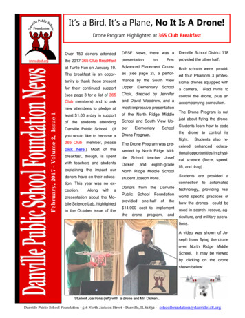
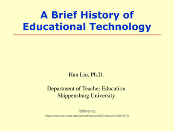
Fig. 5: From left to right: Minimal frequency surface,repeating-texture surface, non-repeating texture surface.Fig. 4: Planar error for our position and velocity controllersover three different surfaces captured by an external motioncapture system.F. Offboard SoftwareStudents controlled their drone through a webpage builtwith Robot Web Tools [15]. This interface allowed them toread data from their sensors, arm or disarm the drone, andissue velocity or position commands (Figure 3). Our browserbased approach allows students to fly their drones withoutneeding to download any programs to their base station.Users interested in extending the drone’s capabilities beyondthe scope of the course can easily interface the drone withan off-board computer using ROS instead of this browserinterface. The Raspberry Pi can either host its own WiFiaccess point or connect to an external network, allowing thebase station to connect to the drone locally.Students used our lab’s reactive-variables framework tosend high-level sequences of commands to the PiDrone. Thisframework allows students to sequence behaviors such as“take off, fly forward, hover, perform position hold, wait1 minute, land.” This framework runs off-board on a ROScapable machine, but in the future we plan to explore runningit onboard the Pi.V. ROBOT P ERFORMANCEThe drone communicates with the Skyline32 at 25 Hz,allowing our software on the Pi to get IMU orientationupdates and send new attitude commands to the Skyline32at 25 Hz.The drone is able to process motion vectors from theH.264 pipeline and estimate velocity at 80 Hz and positionat 10 Hz with 20% and 50% of the Pi’s total CPU powerrespectively. In comparison, an implementation of the samepipeline in C without ROS (courtesy of an ambitiousstudent, Frederick Rice) is able to estimate velocity at 85 Hz,position at 13 Hz using 3% and 70% of the CPU respectively.We suspect the increased power consumption in positionhold in Rice’s C pipeline is due to inefficient handling ofcamera frames. The frequency of velocity estimation appearsto be limited by the frame rate of the camera, leading tominimal performance gain in C . In position hold, bothimplementations make a call to the same OpenCV function,estimateRigidTransform, and most of the overheadis in that function resulting in similar loop frequencies. Thus,we conclude that the performance gained by forgoing ROSand using C instead of Python does not outweigh thepedagogical benefits of ROS and Python.The PiDrone shows robust position-hold performance.Using a motion capture setup for ground truth, we foundthat the drone was able to remain within 0.2 meters of thetarget position. In practice this level of performance meansthe drone can perform position hold over a textured surfacefor the entire battery life of the drone.Figure 4 shows the distance of the the PiDrone from astarting point while flying over the various surfaces picturedin Figure 5. The drone is best able to hold its position whenflying over a high-frequency, non-repeating pattern. When invelocity mode, the drone performed similarly on repeatingand non-repeating textured surfaces, but uniform-color floorsor other surfaces without enough high-frequency features leftthe drone without an accurate velocity estimate. The dronewould “slide” along such surfaces, behaving much like a caron a patch of ice.In the lab-space where students flew most frequently, weprovided a patterned cardboard pad embellished with highfrequency hand-drawn designs shown in 5. Multi-coloredcarpets also worked relatively well for velocity hold. Wealso found that by moving a textured poster under theaircraft while flying in velocity hold, the PiDrone is ableto athletically “chase” what it sees with its downward facingcamera as it tries to drive its visually-observed velocity tozero.During the course, there were rarely more than a fewstudents attempting to fly their drones in our lab space.With this limited number of required WiFi connections,we did not notice any network degradation in most cases.However, when multiple students published a video feed,
the network would only support a few drones at a time. Atthe end of the semester, we attempted to fly all students’drones at the same time in the same location, as depictedin Figure 1. In this case, we noticed substantial drops innetwork performance that led to unsatisfactory drone latency.We believe that the network performance loss was a resultof the numerous independent and overlapping WiFi networksthe drones launched. A possible solution to this problem ishaving the drones and base stations connect wirelessly to onerouter.VI. C LASS A RCHITECTUREAfter developing the PiDrone platform, we developed aclass [16] centered around our core educational goals andthe capabilities of the new system. We wanted students togain an in-depth understanding of all systems on their robotthrough a series on hands-on projects. We designed theseprojects to target specific subsystems of the drone, startingfrom the ground up.Given that the projects were based mostly around buildingthe drone and its autonomous capabilities, we wanted togive the students some familiarity with prerequisite systems,software, and concepts before applying them to the drone.We created homework assignments to introduce relevantskills before using them on the projects. For example,the first three homeworks were on safety, debugging, andROS, all important skills that the students required beforeprogramming their drones.Students assembled their drones as the first project. Thebuild process involved workshops to introduce technicalskills such as soldering and cable management, as wellas a lecture to explain the hardware systems and basicvehicle dynamics. Throughout the course we held studentsresponsible for debugging and maintaining their PiDrones,so developing hardware literacy and understanding of thesystem upfront was crucial for enabling students to workthrough hardware issues as they arose. Thorough knowledgeof their drone’s hardware allowed the students to betterimplement and debug their software, as they had a betterunderstanding of the underlying physical systems.The PiDrone’s spinning propellers and high speed posedpotential safety risks, so it was particularly important toemphasize safety before any students flew their drone. Asstudents worked on assembling their drones for their firstproject, we spent two weeks discussing safety. We introducedthe FAA rules for unmanned aerial vehicles and studied anNTSA crash report in depth as a homework. This processtriggered discussions of safety in robotics generally, and theresponsibility of the operator and the engineer to ensure safeoperation.Subsequent lectures centered on topics that the studentswould implement, such as PID controllers, optical flow,and sensor smoothing, using these concepts to introduce anoverview of the field of robotics. We consistently comparedfeatures of the PiDrone’s hardware and software stacks, tothe technologies developed elsewhere in robotics in order toshow the generalization of the concepts the students learned.There were also several guest lectures from industry andacademia to give students a broader taste of the field.For the second project, students implemented a simplePID in Python to control the altitude of their drone basedon range values from the downward-facing IR sensor. Theyvalidated and tuned their controllers in a simulated environment before transitioning to testing on the PiDrone ina constrained environment — the drones were mounted to aslider which allowed them only to move up and down. Oncethey achieved stable control, students removed their dronesand their altitude controllers on the free-flying drone. Thisenabled the students to gain confidence by testing their codein a safe environment before testing on the robot.The third project required students to estimate the motionof the drone using optical flow. This included sensor smoothing and sensor integration, as students had to use IMU datato correct perceived optical flow for the rotation of the drone.Students then implemented a two axis PID controller whichenabled the drone to maintain a target velocity in the plane.To close the loop and enable position control, studentsestimated the drones position and wrote controllers to modulate the set-point of the velocity controller to achievea target position in the fourth project. This introduced acommon robotics tool, OpenCV, and demonstrated the powerof layered control systems.With a closed-loop, position-controlled drone, the fifthproject explored higher level behavior using our lab’sreactive-variable framework. Students were able to programtheir drones to perform semi-autonomous behaviors, such ashopping from one location to another.VII. D ISCUSSIONThe course outcomes validated our choice of drone design,as 24 of the 25 original students successfully built a droneand completed all five projects in the class. While therewere several instances of components breaking on students’drones, none needed to be rebuilt from scratch and identifying the broken hardware gave students the opportunity todebug the problem and repair their own aircraft.We also realized that the class must strike a delicatebalance of breadth and depth. On one hand, as we intendthe course to be an introduction to robotics, it is importantto introduce students to a wide view of the skills required tobecome a successful roboticist. On the other hand, studentsmust come away with a deep enough understanding ofindividual topics that they will be able to apply them toreal problems. Some students gave feedback that they wouldhave preferred deeper coverage on some topics. For example,students used the optical flow implementation provided bythe Raspberry Pi, and we did not cover the algorithm indepth. More technical depth on specific algorithms like thisdid not fit with our vision for the course, but may fit insimilar courses.Another important piece of student feedback was thatPID tuning assignments became too tedious. Students spentsubstantial time tuning their altitude and planar PID controls.After the experience of tuning the altitude control, the planar
PID tuning often required several more hours of tuning,yielding significantly less educational value.VIII. F UTURE W ORKIn future iterations of the course, students will still tunethe altitude PID controller as they did in project 2 as tuningis an important skill when working with robotic systems.However, for subsequent PID projects we will give themreasonable parameters that are known to work after they haveimplemented their own controllers. This may still requiresome fine-tuning, but will save significant time compared tostarting from scratch.We plan to investigate the addition of an Extended KalmanFilter (EKF) project to the course. State estimation, particularly Kalman Filters, are critical to most mobile robots.Unfortunately, they are significantly more complicated thanmany of the other topics in the class, so a balance must bestruck between the accessibility of the course, and extent towhich we ask students to understand an EKF
plemented onboard in Python using the ROS framework [1]. An onboard camera, infrared distance sensor, and IMU allow the drone to maintain target velocities and positions. We also developed an introductory college-level robotics course with the PiDrone at its core. The course can be taken directly after a first-year computer science course and