Transcription
Lecture notes for Programmable Logic ControllerSubject Code :Subject: PLC AND SCADAPrepared by : S.RAJA, Assistant Professor, Department of EEEUNIT ITable of ContentsPage No.1. Aim and Objective22. Prerequisites23. Pre Test- MCQ type34. Programmable Logic Controller34.1. Introduction44.2. Block diagram of PLC44.3. Input and output module54.4. CPU module94.5. Power Supply105. Post test-Multiple Choice Questions116. Conclusion127. References128. Assignment121
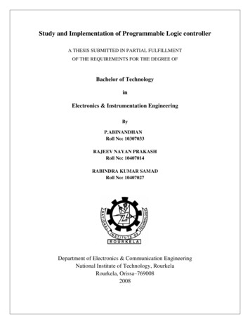
Programmable Logic Controller- Block diagram1. Aim and Objective:To study of the Programmable Logic Controller.2. Prerequisites:Electrical MachinesPower electronicsControl systemBasic C programming3. Pre Test- MCQ type1. Construction of BLDC is exactly similar to thea) Conventional DC motorb) Induction motorc) Permanent magnet synchronous motord) Totally different constructionANSWER: c) Permanent magnet synchronous motor2. Typical brushless motor doesn’t havea) Commutatorb) Permanent magnetc) Electronic controllerd) Fixed armatureANSWER: a) Commutator3.PWM DUTY RATIO IS----------------a) TON/(TON TOFF)*100b) ((TON TOFF)/TON)*100c) ((TON TOFF)/TOFF)*100ANSWER : TON/(TON TOFF)*1004.Advantages of Digital signal processinga)b)c)d)Fast processing – parallelGuarantee accuracy – no of bitsExact reproduction or repeatabilityAll of the above2
ANSWER : d) All of the above4. Programmable Logic Controller:4.1. Introduction:A programmable logic controller (PLC) is a specialized Programmable device which is usedto control machines and processes.It uses a programmable memory to store instructions and execute specific functions thatinclude on/off control, timing, counting, sequencing, arithmetic, and data handling.Advantages Increased Reliability More Flexibility Lower Cost Communications Capability Faster Response Time Easier to Troubleshoot4.2 PLC Block diagram3
Central Processing UnitIt is heart of the PLC . CPU is used to store the program, reads the status of inputsthrough the input module and execute the stored program and appropriate output to beactivated based on the logicCPU has two memory section one section used to store the program and other section is usedto store the dataInput Module The I/O system forms the interface by which field devices are connected to thecontroller. The purpose of this interface is to condition the various signals received from or sentto external field devices. Input devices such as pushbuttons, limit switches, sensors. Selector switches. andthumbwheel switches are hardwired to terminals on the input modules.Output Module Output devices such as small motors, motor starters, solenoid valves. and indicatorlights are hardwired to the terminals on the output modules.Programming device The programming device is used to enter the desired program into the memory ofprocessor. Ladder logic programming language uses instead of words, graphic symbol. It is a special language written to make. it easier for people familiar with relay logiccontrol to programPower Supply4
Leading manufacturer for PLC Allen Bradley ABB Siemens Mitsubishi PLC Hitachi PLC Delta PLC General Electric (GE) PLC Honeywell PLC4.3Input/Output Module The I/o system provides an interface between the hardwired components in the fieldand the CPU.Input ModuleDiscrete Input Module This type of interface connects field input devices of the ON/OFF nature such asselector switches, pushbuttons and limit switches. Likewise, output control is limited to devices such as lights, small motors, solenoids,and motor starters that require simple ON/OFF switching. It is interface between the Input field device and CPU of PLCInput modules perform four tasks in the PLC control system. sense when a signal is received from a sensor on the machine convert the input signal to the correct voltage level for the particular PLC isolate the PLC from fluctuations in the input signal's voltage or current send a Signal to the processor indicating which sensor originated the signal5
An input filter removes unwanted signal from the electrical interference or keybouncing issueOpto –electrical isolating section is used to protects the any short circuit fault or highvoltage surge from high voltage circuit to logic circuit which normally operatedby low voltageLogic section in the module is used to process the input signal based the pre designedlogic and turns ON or OFF the LEDDiscrete Output Module Discrete output modules typically use the same form of opto-isolation to allow thePLC’s computer circuitry to send electrical power to loads: it is composed of two basic sections:the power section and the logic section , coupled by an isolation circuit.6
The output interface can be thought of as a simple electronic switch to which power isapplied to control the output device. Discrete output modules are used to turn real world output devices either on or off. These modules can be used to control any two-state device. and they are available inac and dc versions and in various voltage ranges and current ratings. Output modules can be purchased with transistor. triac. or relay output. Triac outputs can be used only for control of ac devices. whereas transistor outputscan be used only for control of dc devices. Relay outputs can be used with ac or dcdevices.Analog I/O Module Interface with an analog sensor or control device with CPU of PLC through ADC. Analog-to-Digital Converter, circuit designed to convert an analog electrical signalinto a multi-bit binary word Voltage (0 to 10 volt, 0 to 5 volt) Current (0 to 20 mA, 4 to 20 mA)Thermocouple (millivoltage)7
Analog input modules Analog input interface modules contain the circuitry necessary to accept analogvoltage or current signals from analog field devices. These inputs are converted from an analog to a digital value by an analog-lo-digital(AID) converter circuit. The conversion value, which is proportional to the analog signal, is expressed as a 12bit binary or as a 3-digit binary-coded decimal (BCD) for use by the processor.Analog input interface moduleconnection to a thermocouple A varying dc voltage in the millivolt range. proportional tothe temperature beingmonitored. is produced by the thermocouple. This voltage is amplified and digitized by the analog input module and then sent tothe processor on command from a program instruction. Because of the low voltage level of the input signal, a shielded cable is used in wiringthe circuit to reduce unwanted electrical noise signals that can be induced in theconductors from other wiring. This noise can cause temporary operating errors that can lead to hazardous orunexpected machine operationAC output Module8
When the processor calls for an output, a voltage is applied across the LED of theisolator. The LED then emits light, which switches the phototransistor into conduction. Thisin turn (5 V dc)switches the triode DC semiconductor switch (triac) into conduction.which in turn turns on the lamp. Since the triac conducts in either direction, the output to the lamp is alternatingcurrent. The triac, rather than having ON and OFF status. actually has LOW andHIGH resistance levels, respectively. In its OFF state (HIGH resistance), a small leakage current of a few milliamperes stillflows through the triac. As with input circuits, the output interface is usually provided with LEDs that indicatethe status of each output.4.4.CPU Module The CPU contains the same type of microprocessor found in a personal computer. The difference is that the program used with the microprocessor is designed tofacilitate industrial control rather than provide general purpose computing. The CPU executes the operating system, manages memory, monitors inputs, evaluatesthe user logic (ladder program),and turns on the appropriate outputs. The CPU of a PLC system may contain more than one microprocessor. The advantage of using multiprocessing is that control and communication tasks canbe divided up. And the overall operating speed is improved.9
Processor operating modeRUN, PROG, and REM(Remote).4.5.Power supply Module The power supply module is a necessary and important component of the controlsystem. It is used to safely regulate and supply the voltage necessary for the PLC and othermodules installed on the rack. The module is typically installed in the first slot of the rack. The output voltage of the power supply that we use is typically 24 volts DC. The output current varies depending on the number of the modules needed in thecontrol system. For instance, this output current could be 2, 5 or 10 Ampere.10
Depending on which and how many modules are used, the output current of the powersupply may need to be higher.5.Post test MCQWhich one of the following is not advantages of PLCIncreased Reliabilityless FlexibilityLower CostEasier to TroubleshootWhich module is used for implementing the logic and controlling the communicationsamong the modules PLC.Power supply moduleCommuniation moduleProcessor moduleInput moduleThe ----------------provides an interface between the hardwired components in the fieldand the CPUCommunication modulePower supply moduleProcessor moduleInput and Output moduleIn Discrete output module, Relay outputs can be used control theAC Devices11
DC DevicesBoth AC and DC devices.None of the above6. ConclusionThe block diagram of Programmable Logic Controller discussed and briefed about theeach of the block in details7. References1. Gary Dunning, “Introduction Programmable Logic Controllers”, CENGAGELearning, 3rd Ed., 2006.2. John R. Hackworth, Frederick D. Hackworth Jr., “Programmable LogicControllers”, Pearson, 2004.3. Bolton, “Programmable Logic Controllers”, Elsevier, 4th Ed., 2006.Assignment1. Explain the PLC block diagram in detail2. Describe about the analog input and output module of the PLC3. Write short about the PLC operation and PLC scan cycle.12
Lecture notes for Programmable Logic ControllerSubject Code :Subject: PLC AND SCADAPrepared by : S.RAJA, Assistant Professor, Department of EEEUNIT-2 Basic Programming of PLCTable of ContentsPage No.1. Aim and Objective22. Prerequisites23. Pre Test- MCQ type34. Basic Programming of Programmable Logic Controller34.1. Ladder diagam44.2. PLC Instructions64.3. Implementation of logic gates using ladder114.4. Simple Programs175. Post test-Multiple Choice Questions186. Conclusion197. References198. Assignment201
1. Aim and ObjectiveLearn about the programming of the PLCImplementation of basic logic gates using ladder programming2. PrerequisitesBasic knowledge of logic gatesPLC block diagram3. Pre Test- MCQ type1. The output of the two input NAND gate is high whena) Only If the both inputs are highb) Only If the both inputs are lowc) Only If the one input is high other one is lowd) If at least one of the input is low2. A XOR gate has inputs A and B and output Y. Then the output equation isa) Y ABb) Y AB A’ Bc) Y A’ B A B’d) Y AB A’ B’3. A solenoid is an example of an ---------------output device.a) Trueb) Falsec )None of the above4.Which module is used for implementing the logic and controlling the communicationsamong the modules PLC.a)Power supply moduleb) Communication modulec) Processor moduled) Input module5. Which one of the following is an input device?a) Motor2
b) Lightc) Valved) Sensor4. Basic programming of PLCThe 5 most popular types of PLC Programming Languages are: Ladder Diagram (LD) Sequential Function Charts (SFC) Function Block Diagram (FBD) Structured Text (ST)Instruction List (IL)4.1 Ladder Diagram (LD) Ladder logic is the simplest form of PLC programming. It is also known as “relay logic”. The relay contacts used in relay controlled systemsare represented using ladder logic. Functional Block Diagram (FBD) is a simple and graphical method to programmultiple functions in PLCAdvantages of the Ladder Diagram (LD) It is easily programmed and has an easily understood programming language. It has flexibility in programming and reprogramming. Troubleshooting is easier and fasterRules to draw the ladder logic diagram The ladder diagram consists of two vertical lines representing the power rails. Circuits are connected as horizontal lines, i.e., the rungs of the ladder, between thesetwo verticals.3
1. The vertical lines of the diagram represent the power rails between which circuits areconnected. The power flow is taken to be from the left-hand vertical across a rung.2. Each rung on the ladder defines one operation in the control process.3. A ladder diagram is read from left to right and from top to bottom, showing thescanning motion employed by the PLC.The top rung is read from left to right. Then the second rung down is read from left toright and so on.4. Each rung must start with an input or inputs and must end with at least one output. Theterm input is used for a control action, such as closing the contacts of a switch, used as aninput to the PLC. The term output is used for a device connected to the output of a PLC,e.g., a motor.5. Electrical devices are shown in their normal condition. Thus a switch, which isnormally open until some object closes it, is shown as open on the ladder diagram. Aswitch that is normally closed is shown closed.4
6. A particular device can appear in more than one rung of a ladder. For example, wemight have a relay that switches on one or more devices. The same letters and/or numbersare used to label the device in each situation.7. The inputs and outputs are all identified by their addresses, the notation used dependingon the PLC manufacturer. This is the address of the input or output in the memory of thePLC.8.The instructions used are the relay equivalent of normally open (NO) and normallyclosed (NC) contacts and coils.9.Contact symbolism is a simple way of expressing the control logic in terms of symbolsthat are used on relay control schematics.10.A rung is the contact symbolism required to control an output. Some PLCs allow arung to have multiple outputs.11.A complete ladder logic program thus consists of several rungs. each of which controlsan output.12.Because the PLC uses ladder logic diagrams. the conversion from any existing relaylogic to programmed logic is simple.13. Each rung is a combination of input conditions (symbols) connected from left to right,with the symbol that represents the output at the far right.14.The symbols that represent the inputs are connected in series, parallel. or somecombination of the two to obtain the desired logic.15.Because the PLC uses ladder logic diagrams. the conversion from any existing relaylogic to programmed logic is simple.16. Each rung is a combination of input conditions (symbols) connected from left to right,with the symbol that represents the output at the far right.17.The symbols that represent the inputs are connected in series, parallel. or somecombination of the two to obtain the desired logic.RUNG A type of line diagram that uses the input and output symbols used by PLC ladderlogic. Line diagrams are converted to programming diagrams before being entered intoa PLC5
4.2 PLC InstructionsRELAY-TYPE INSTRUCTIONS The ladder diagram language is basically asymbolic set of instructions used to create the controller program. The three fundamental symbols that are used to translate relay control logic to contactsymbolic logic are EXAMINE IF CLOSED,EXAMINE IF OPEN, and OUTPUTENERGIZENormally open Analogous to the normally open relay contact. For this instruction. we ask the processor to EXAMINE IF (the contact is) CLOSED. The status bit will be either1(ON) or 0 (OFF) The status bit is examined for an ON condition. If the status bit is I (ON). Then the instruction is TRUE.6
If the status bit is 0 (OFF). Then the instruction is FALSE.Normally closed instruction, we ask the processor to EXAMINE IF (the contact is) OPEN. The status bit will be either 1 (ON) or 0 (OFF). The status bit is examined for an OFF condition. If the status bit is 0 (OFF), then the instruction is TRUE. It the status bit is 1 (ON), then the Instruction is FALSE.7
Relay coil (OTE) The processor ( makes it is Instruction true (analogous to energizing a coil) whenthere is a path 01 true XIC and XIO instructions in the rung. If any left to right path of input conditions is TRUE. the output is energized (turnedON). The status bit 01 the addressed OUTPUT Energize instruction is set to 1 (ON) whenthe rung is TRUE.8
The status bit 01 the addressed OUTPUT Energize instruction is reset 10 0 (OFF)when the rung is FALSE.Branching instructions Branch instructions are used to create parallel paths of input condition instructions. This allows more than one combination of input conditions (OR logic) to establishlogic continuity in a rung. The rung will be true if either instruction A or B is TRUE.Types1. Parallel input Branching2. Parallel input Branching with Output branching3. Parallel output branching with input4. Nested branching9
Parallel input Branching Input branching by formation of parallel branches can be used in your application program to allow more than one combination of input conditions, If at least one of these parallel branches forms a true logic path, the rung logic isenabled. If none of the parallel branches forms a true logic path. rung logic is not enabled andthe output instruction logic will not be TRUE. In the example shown, either A and B or C provides a true logical path.Parallel input Branching with Output branching branches can be established at both input and output portions of a rung. With outputbranching. you can Program parallel outputs on a rung to allow a true logic path to controlmultiple outputs. When there is a true logic path. all parallel outputs become TRUE. either A or B provides a true logical path to all three output instructions: C, D, and E.Parallel output branching with input10
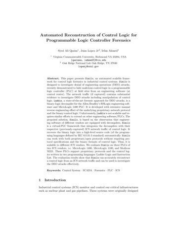
Additional input logic instructions (conditions) can be programmed in the outputbranches to enhance condition contra) of the outputs. When there is a true logic path, including extra input conditions on an output branch.That branch becomes TRUE. either A and D or Band D provide a true logic path to E.Nested Input and output branches can be nested to avoid redundant instructions and to speedup processor scan time. Input and output branches can be nested to avoid redundant instructions and to speedup processor scan time.4.3. Implementation of logic gates using ladderAND LogicIt is a basic gate. Whenever the all the input condition must true then output becomestrueFigure (a)Truth table of the AND logic (b) block diagram of AND logic11
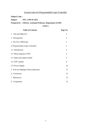
Logic equationLadder Logic diagram for AND LogicOR LOGICIt is basic gate. Whenever any one of the input conditions is true the output becomes true12
Figure (a)Truth table of the OR logic (b) block diagram of OR logicLogic equationY A BLadder logic diagram of the OR logic Two limit switches connected in parallel and used to control a solenoid valve.NOT logicIt is one of the basic logic gate output always the complement of inputTruth Table of NOT logicLadder logicNOT logicdiagram of13
NAND LOGICIt is an universal gate. Whenever the all the input must true condition the output becomesfalse orIf any one of the inputs is false condtion then output becomes true.Truth Table of the NAND LogicLogic Equation of the NAND LogicLadder Logicdiagram for NAND logic14
NOR LogicIt is an universal gate. Whenever all the input conditions are false then output becomes trueTRUTH TABLE of the NOR logicLOGIC equationLadder logic diagram for NOR logicExclusive OR The output of this circuit is ON only when pushbutton A or B is pressed, but not both.Case 1When A 0 and B 0:Let us analyze main rung. When I1 0, the normally open instruction is false and,normally closed instruction is true, but since normally open instruction is false, there is nological continuity and output cannot be energized. Similar analysis can be done in parallel15
rung, normally closed instruction will be true and normally open instruction will be falseand output is not energized.Case 2When A 0 and B 1:In main rung, normally open instruction will be false and, normally closed instruction willbe true, but since there is no logical continuity this rung logic cannot energize the output.But, in parallel rung, normally closed instruction will be true, as well as normally openinstruction will also be true, hence there is logical continuity, and output is energized.Case 3 When I1 1 and I2 0:This case is similar to case 2, only the role of inputs are interchanged i.e. here main rung istrue and energizes the output and parallel rung is false.Case 4 When both inputs are true, the main ladder rung as well as the parallel ladder runggoes false. In main rung, normally open instruction is true but normally closedinstruction is false. Hence, there is no logical continuity. In parallel ladder rung,normally closed instruction is false and normally open instruction is true, and herealso there is no logical continuity. Hence, the output is not energized.16
Latch circuit There are often situations where it is necessary to hold an output energized, evenwhen the input ceases. A simple example of such a situation is a motor, which is started by pressing a pushbutton switch. Though the switch contacts do not remain closed, the motor is required to continuerunning until a stop push button switch is pressed. The term latch circuit is used for the circuit used to carry out such an operation. It is a self-maintaining circuit in that, after being energized, it maintains that stateuntil another input is received.4.4.Simple Programs A lighting control system is to be developed. The system will be controlled by four switches,SWITCH1, SWITCH2, SWITCH3, and SWITCH4.These switches will control the lighting in a room based on the following criteria:1. Any of three of the switches SWITCH1, SWITCH2, and SWITCH3, if turned ON can turnthe lighting on, but all three switches must be OFF before the lighting will turn OFF.2. The fourth switch SWITCH4 is a Master Control Switch. If this switch is in the ONposition, the lights will be OFF and none of the other three switches have any control.Design the wiring diagram for the controller connections, assign the inputs and outputs anddevelop the ladder diagram which will accomplish the task.Number of PLC Inputs Required INPUT IN1 SWITCH1 INPUT IN2 SWITCH2 INPUT IN3 SWITCH3 INPUT IN4 SWITCH4 (Master Control Switch)17
Number of PLC Outputs Required OUTPUT OUT1 Lights control relay coil CR1 Any of three of the switches SWITCH1, SWITCH2, and SWITCH3, if turned ON can turnthe lighting on The fourth switch SWITCH4 is a Master Control Switch. If this switch is in the ON position,the lights will be OFFBoolean logicCR1 (IN1 OR IN2 OR IN3) AND IN45. POST MCQ1. Function Block Diagram (FBD) is a type of .a) PLC Language18
b).Block Diagram of a CPU modulec) Block Diagram of a PLC modeld) None of the above2. The each line used in Ladder Language Programming is known as .a) Ringb) Wrongc) Rungd) None of the above3. The symbol shown below in the ladder diagram ---------------a)b)c)d)can be thought of as a contact that is usually closed.can be thought of as a contact that is usually opened.is always a logic 0.is always a logic 1.4. A two input OR logic function implemented in ladder logic uses:a)Two normally-closed contacts in seriesb) Two normally-open contacts in seriesc) Two normally-open contacts in paralleld) Two normally-closed contacts in parallel5.Which one of the following logic gate is universal logic gatea)b)c)d)XORXNORNORAll of the above6. Normally closed contact also known asa) Examine if openb) Examine if closed.c) Relay coil19
d) None of the above6. ConclusionThe basic programming of Programmable Logic Controller discussed and briefed7. References1. Gary Dunning, “Introduction Programmable Logic Controllers”, CENGAGELearning, 3rd Ed., 2006.2. John R. Hackworth, Frederick D. Hackworth Jr., “Programmable LogicControllers”, Pearson, 2004.3. Bolton, “Programmable Logic Controllers”, Elsevier, 4th Ed., 2006.8. Assignment1. Implement PLC program to control water level of the tank. One open tank isinstalled in the plant of which liquid level is to be controlled. When level reachesthe Level Low, Outlet flow is blocked and inlet flow is allowed until high level isachieved. And when Level High is detected, outlet flow is allowed and inlet flowis blocked.2. Implement the 4:1multiplexer using ladder logic diagram3. The rung --] [-----]/[-----( )-- would represent what Boolean equation?XYZand draw the equivalent logic diagram usinggate20
4. Programmable Logic Controller: 4.1. Introduction: A programmable logic controller (PLC) is a specialized Programmable device which is used to control machines and processes. It uses a programmable memory to store instructions and execute specific functions that include on/off control, timing, counting, sequencing, arithmetic, and data handling.