Transcription
Logix 5000 ControllersInformation and Status1756 ControlLogix, 1756 GuardLogix, 1769 CompactLogix,1769 Compact GuardLogix, 1789 SoftLogix, 5069CompactLogix, 5069 Compact GuardLogix, Studio 5000Logix EmulateRockwell Automation Publication 1756-PM015M-EN-P - March 2022Supersedes Publication 1756-PM015L-EN-P - November 2020Programming ManualOriginal Instructions
Logix 5000 Controllers Information and StatusImportant User InformationRead this document and the documents listed in the additional resources section about installation, configuration, andoperation of this equipment before you install, configure, operate, or maintain this product. Users are required to familiarizethemselves with installation and wiring instructions in addition to requirements of all applicable codes, laws, and standards.Activities including installation, adjustments, putting into service, use, assembly, disassembly, and maintenance are required tobe carried out by suitably trained personnel in accordance with applicable code of practice.If this equipment is used in a manner not specified by the manufacturer, the protection provided by the equipment may beimpaired.In no event will Rockwell Automation, Inc. be responsible or liable for indirect or consequential damages resulting from the useor application of this equipment.The examples and diagrams in this manual are included solely for illustrative purposes. Because of the many variables andrequirements associated with any particular installation, Rockwell Automation, Inc. cannot assume responsibility or liability foractual use based on the examples and diagrams.No patent liability is assumed by Rockwell Automation, Inc. with respect to use of information, circuits, equipment, or softwaredescribed in this manual.Reproduction of the contents of this manual, in whole or in part, without written permission of Rockwell Automation, Inc., isprohibited.Throughout this manual, when necessary, we use notes to make you aware of safety considerations.WARNING: Identifies information about practices or circumstances that can cause an explosion in a hazardous environment, which may lead to personal injuryor death, property damage, or economic loss.ATTENTION: Identifies information about practices or circumstances that can lead to personal injury or death, property damage, or economic loss. Attentionshelp you identify a hazard, avoid a hazard, and recognize the consequence.IMPORTANT Identifies information that is critical for successful application and understanding of the product.Labels may also be on or inside the equipment to provide specific precautions.SHOCK HAZARD: Labels may be on or inside the equipment, for example, a drive or motor, to alert people that dangerous voltage may be present.BURN HAZARD: Labels may be on or inside the equipment, for example, a drive or motor, to alert people that surfaces may reach dangerous temperatures.ARC FLASH HAZARD: Labels may be on or inside the equipment, for example, a motor control center, to alert people to potential Arc Flash. Arc Flash will causesevere injury or death. Wear proper Personal Protective Equipment (PPE). Follow ALL Regulatory requirements for safe work practices and for PersonalProtective Equipment (PPE).Rockwell Automation recognizes that some of the terms that are currently used in our industry and in this publication are not inalignment with the movement toward inclusive language in technology. We are proactively collaborating with industry peers tofind alternatives to such terms and making changes to our products and content. Please excuse the use of such terms in ourcontent while we implement these changes.2Rockwell Automation Publication 1756-PM015M-EN-P - March 2022
Summary of ChangesThis manual includes new and updated information. Use these referencetables to locate changed information.Grammatical and editorial style changes are not included in this summary.Global changesThis table contains a list of topics changed in this version, the reason for thechange, and a link to the topic that contains the changed information.Topic NameReasonStudio 5000 environmentComponent trackingUpdated Studio 5000 Logix Designer branding image.Updated the supported versions for component tracking to version30 or later.Added four missing log entries: Vendor Certificate Status, Port statemodified, Constant Tag attribute set, and Constant Tag attributeclear.Controller Log EventsRockwell Automation Publication 1756-PM015M-EN-P - March 20223
Table of ContentsSummary of ChangesPrefaceIn this manual . 7Studio 5000 environment . 7Additional Resources . 7Legal Notices . 8Chapter 1ConnectionsIntroduction . 9Inhibit a Connection. 9Manage a connection failure . 11Configure a major fault to occur . 12Monitor the health of a module. 13Determine controller memoryinformationController loggingChapter 2Introduction . 17View data usage. 17Capacity tab for controllers that divide memory . 17Capacity tab for controllers with common memory area . 18Estimate memory information offline for controllers with dividedmemory . 19View run-time memory information for controllers with dividedmemory . 20View the maximum and used Ethernet nodes for a controller . 21Write logic to get memory information . 22Get memory information from the controller . 22Choose the memory information.23Convert INTs to a DINT .23Chapter 3Introduction . 25Controller log . 25Controller log header . 26Controller log entry . 26Entries captured in the controller log . 27Controller log buffer . 28Controller log files and the removable media . 28Writing the controller log to the SD card . 28Automatic save . 29Save on demand . 30Controller logging counters . 31Total entry count . 31Unsaved entry count .32Rockwell Automation Publication 1756-PM015M-EN-P - March 20225
Table of ContentsExecution modification count .32Log file storage . 35Log file format .36Create Custom Log Entries . 37Sample Ladder Logic File . 38Controller Log Events . 38Change detectionAccess status informationIndex6Chapter 4Introduction . 47Controller change detection . 47ChangesToDetect .47AuditValue . 49ChangesToDetect format . 49Change detection in the Logix Designer application . 50Component tracking . 51Track the state of components and constant tags . 52View tracked components . 53Retrieve the tracked state value using a Message instruction. 53Chapter 5Introduction . 55Status of S:FS when the project has an SFC. 55Get and set system data .56Rockwell Automation Publication 1756-PM015M-EN-P - March 2022
PrefaceIn this manualThis manual describes how Logix 5000 controllers use connections with otherdevices. This manual also describes status keywords and how to get controllerinformation, such as memory resources. This manual is one of a set of relatedmanuals that show common procedures for programming and operatingLogix 5000 controllers.For a complete list of common procedures manuals, refer to the Logix 5000Controllers Common Procedures Programming Manual, publication1756-PM001.The term Logix 5000 controller refers to any controller based on the Logix5000 operating system.Studio 5000 environmentThe Studio 5000 Automation Engineering & Design Environment combinesengineering and design elements into a common environment. The firstelement is the Studio 5000 Logix Designer application. The Logix Designerapplication is the rebranding of RSLogix 5000 software and will continue tobe the product to program Logix 5000 controllers for discrete, process,batch, motion, safety, and drive-based solutions.The Studio 5000 environment is the foundation for the future ofRockwell Automation engineering design tools and capabilities. The Studio5000 environment is the one place for design engineers to develop allelements of their control system.Additional ResourcesThese documents contain additional information concerning relatedRockwell Automation products.ResourceDescriptionIndustrial Automation Wiring and Grounding Guidelines,publication, 1770-4.1Provides general guidelines for installing a RockwellAutomation industrial system.Product Certifications website, http://www.ab.comProvides declarations of conformity, certificates, andother certification details.Rockwell Automation Publication 1756-PM015M-EN-P - March 20227
PrefaceView or download publications athttp://www.rockwellautomation.com/literature. To order paper copies oftechnical documentation, contact a local Rockwell Automation distributor orsales representative.Rockwell Automation recognizes that some of the terms that are currentlyused in our industry and in this publication are not in alignment with themovement toward inclusive language in technology. We are proactivelycollaborating with industry peers to find alternatives to such terms andmaking changes to our products and content. Please excuse the use of suchterms in our content while we implement these changes.Legal NoticesRockwell Automation publishes legal notices, such as privacy policies, licenseagreements, trademark disclosures, and other terms and conditions on theLegal Notices page of the Rockwell Automation website.End User License Agreement (EULA)You can view the Rockwell Automation End-User License Agreement ("EULA")by opening the License.rtf file located in your product's install folder on yourhard drive.Open Source LicensesThe software included in this product contains copyrighted software that islicensed under one or more open source licenses. Copies of those licenses areincluded with the software. Corresponding Source code for open sourcepackages included in this product are located at their respective web site(s).Alternately, obtain complete Corresponding Source code by contactingRockwell Automation via the Contact form on the Rockwell m/global/about-us/contact/contact.pagePlease include "Open Source" as part of the request text.A full list of all open source software used in this product and theircorresponding licenses can be found in the OPENSOURCE folder. The defaultinstalled location of these licenses is C:\Program Files (x86)\CommonFiles\Rockwell\Help\ Product Name \ReleaseNotes\OPENSOURCE\index.htm.8Rockwell Automation Publication 1756-PM015M-EN-P - March 2022
Chapter 1ConnectionsIntroductionA Logix 5000 controller uses connections for most, but not all, of itscommunication with other devices.TermDefinitionConnectionA communication link between two devices, such as between a controller and an I/Omodule, PanelView terminal, or another controller.Connections are allocations of resources that provide more reliable communicationbetween devices than unconnected messages. The number of connections that a singlecontroller can have is limited.Configuring the controller to communicate with other devices in the system indirectlydetermines the number of connections the controller uses. These communication typesuse these connections: I/O modules Produced and consumed tags Program parameters Certain types of Message (MSG) instructions (not all types use a connection)Requested packetinterval (RPI)The RPI specifies the period at which data updates over a connection. For example, aninput module sends data to a controller at the RPI assigned to the module. Typically, an RPI is configured in milliseconds (ms). The range is 0.2 ms(200 microseconds) 750 ms. If a ControlNet network connects the devices, the RPI reserves a slot in the stream ofdata flowing across the ControlNet network. The timing of this slot may not coincidewith the exact value of the RPI, but the control system guarantees that the datatransfers at least as often as the RPI.The path describes the route that a connection takes to get to the destination.Typically, the path for a connection is defined when a device is added to the I/OConfiguration folder of the controller.PathInhibit a ConnectionIn some situations, such as when initially commissioning a system, it is usefulto disable portions of a control system and enable them as they are connectedto the control system. Inhibiting individual modules or groups of modulesprevents the controller from trying to communicate with the modules.ATTENTION: Inhibiting a module breaks the connection to the module and preventscommunication of I/O data.An installed I/O module defaults to not inhibited. To inhibit a module, changean individual module’s properties.Rockwell Automation Publication 1756-PM015M-EN-P - March 20229
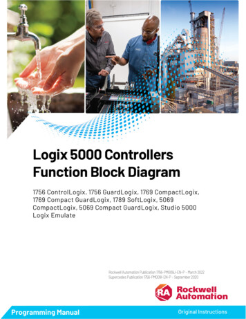
Chapter 1ConnectionsToThenCommunicate with the moduleDo not inhibit the module. Clear the Inhibit Modulecheckbox.Inhibit the module. Select the Inhibit Module checkbox.Prevent communication with the moduleWhen a communication bridge module is inhibited, the controller shuts downthe connections to the bridge module and to all the modules that depend onthat bridge module. Inhibit a communication bridge module to disable anentire branch of the I/O network.When the module is inhibited, the Controller Organizer displays a yellowattention symbol over the module.IfAnd youAndThenOffline------------------------------ -------- OnlineInhibit a module while connected to -------- the moduleThe inhibit status is stored in the project. Whenthe project downloads to the controller, themodule still is inhibited.The connection to the module is closed. Themodule's outputs go to the last configuredProgram mode.Inhibit a module but a connection to -------- the module was not established(perhaps due to an error conditionor fault)Uninhibit a module (clear theNo fault occurscheckbox)Fault occursThe module is inhibited. The module statusinformation changes to indicate that the moduleis inhibited and not faulted.A connection is made to the module and themodule is dynamically reconfigured (if thecontroller is the owner-controller) with theconfiguration created for that module. If thecontroller is configured for listen-only, it cannotreconfigure the module.A connection is not made to the module. Themodule status information changes to indicatethe fault condition.To inhibit or uninhibit a connection1. Use a Get System Value (GSV) instruction to read the Mode attributefor the module.2. To inhibit the module, set bit 2. To uninhibit the module, clear bit 2.3. Use a Set System Value (SSV) instruction to write the Mode attributeback to the module.Example: Inhibit a connection10Rockwell Automation Publication 1756-PM015M-EN-P - March 2022
Chapter 1ConnectionsIf Module 1 Inhibit 1, then inhibit the operation of the I/O module named Module 1. The GSV instruction sets Module 1 Mode value of the Modeattribute for the module. The OTE instruction sets bit 2 of Module 1 Mode 1. This meansinhibit the connection. The SSV instruction sets the Mode attribute for the module Module 1 Mode.Manage a connectionfailureIf the controller loses communication with a module, data from that devicedoes not update. When this occurs, the logic acts on the data in ways that mayor may not be correct. Program the controller to manage faults safely andefficiently.ATTENTION: Outputs respond to the last, non-faulted state of the controlling inputs. Toavoid potential injury and damage to machinery, make sure this does not create anunsafe operation. Configure critical I/O modules to generate a controller major fault whenthey lose their connections to the controller, or monitor the status of I/O modules.Example: Loss of communicationController B requires data from controller A. If communication fails betweenthe controllers, controller B continues to act on the last data that it receivedfrom controller A.Rockwell Automation Publication 1756-PM015M-EN-P - March 202211
Chapter 1ConnectionsIf communication with a device in the I/O configuration of the controller doesnot occur for 100 ms, the communication times out. If this occurs, choosebetween these options.If the controller shouldThenFault (major fault)Configure a major fault to occurContinue operatingMonitor the health of a moduleSee alsoMonitor the health of a module on page 13Configure a major fault tooccur12To force a module to generate a major fault in the controller if it losesconnection with the controller, configure a major fault to occur. Thisinterrupts the execution of logic and runs the Controller Fault Handler. If theController Fault Handler does not clear the fault, the controller shuts down.Rockwell Automation Publication 1756-PM015M-EN-P - March 2022
Chapter 1ConnectionsWhen selecting Major Fault On Controller Run Mode, the controller: Must be connected to the module during the Program transition toRun mode. During the Program to Run mode transition, there can be a20-second delay.During this delay, the controller makes one attempt to connect to amodule. If Major Fault On Controller Run Mode is selected and noconnection occurs during the 20-second delay, a fault occurs becauseat least one required connection is not established before going to Runmode. This is a 3/23 type fault code. This fault can occur in largesystems with networked I/O. Registers a fault if the connection is dropped while in Run mode. Arequired I/O module connection failed, creating a 3/16 type fault.For fault codes, see the Logix 5000 Controllers Major and Minor FaultsProgramming Manual, publication no. 1756-PM014.See alsoLogix 5000 Controllers Major and Minor Faults Programming Manual,publication no. 1756-PM014Monitor the health of amoduleMonitor the module status if the module is not configured to generate amajor fault. If a module loses its connection to the controller, outputs go totheir configured faulted state. The controller and other I/O modules continueto operate based on old data from the module.If communication with a module times out, the controller produces thesewarnings. The I/O status indicator on the front of the controller flashes green. A Warning ( ) icon shows over the I/O configuration folder and overthe device that has timed out. A module fault code is produced, which is accessible through: Module Properties window for the module. GSV instruction.To monitor the health of connections, use a Get System Value (GSV)instruction to monitor the Module object for either the controller or a specificmodule.ToGet thisattributeData TypeRockwell Automation Publication 1756-PM015M-EN-P - March 2022Description13
Chapter 1ConnectionsToDetermine ifcommunication hastimed out with anydeviceGet thisattributeLEDStatusData TypeDescriptionINTFor efficiency, use aDINT as the destinationdata type.Current state of the I/O statusindicator on the front of thecontroller.No need to enter an instance namewith this attribute. This attributeapplies to the entire collection ofmodules.This table describes the meaning of the I/O status indicator on the front of thecontroller.ValueMeaning0Status Indicator off. No Module objects areconfigured for the controller (there are nomodules in the I/O Configuration section ofthe controller organizer).Flashing red. None of the Module objectsare Running.Flashing green. At least one Module objectis not Running.Solid green. All the Module objects areRunning.123ToDetermine ifcommunication hastimed out with aspecific deviceGet thisattributeFaultCodeData TypeDescriptionINTFor efficiency, use aDINT as the destinationdata type.A number that identifies a modulefault, if one occurs.In the Instance Name, choose thedevice with a connection to monitor.Make sure to assign a name to thedevice in the I/O Configuration folderof the project.If Module Status is any value other than 4, the controller is notcommunicating with the module. See the example.Example:This rung checks the status of an I/O connection. The controller checks theentry status of the connection; any value other than 4 indicates that theconnection is not functioning correctly. When the controller detects an error,the error code and information is trapped, and the controller tries tore-establish the connection.14Rockwell Automation Publication 1756-PM015M-EN-P - March 2022
Chapter 1Rockwell Automation Publication 1756-PM015M-EN-P - March 2022Connections15
Chapter 2Determine controller memory informationIntroductionDepending on the type of controller, the memory of the controller is dividedinto several areas.This controllerStores thisIn this memoryControlLogix 5570GuardLogix 5570SCompactLogix 5370Compact GuardLogix 5370SControlLogix 1756-L5x, L6xGuardLogix 1756-L6xSI/O tagsI/O memoryProduced / Consumed tagsCommunication via Message (MSG) instructionsCommunication with workstationsCommunication with polled (OPC/DDE) tags thatuse RSLinx software1Tags other than I/O, produced, or consumed tags Data and logic memory2Logic routinesCompactLogix 1769-L2x, L3xSoftLogix5800CompactLogix 5380CompactGuardLogix 5380CompactLogix 5480ControlLogix 5580GuardLogixlLogix 5580Communication with polled (OPC/DDE) tags thatuse RSLinx software1These controllers do not divide their memory. They store all elements in onecommon memory area.(1) To communicate with polled tags, the controller uses both I/O data andlogic memory.(2) 1756-L55M16 controllers have an additional memory section for logic.View data usageIn the Logix Designer application, the Capacity tab (formerly the Memorytab) on the Controller Properties dialog box shows data usage in thecontroller. The data displayed on the Capacity tab depends on the controller.Tip: Refer to the Memory information table to see whether a controller divides its memory orhas one common memory area.See alsoMemory information table on page 17Capacity tab for controllersthat divide memoryThe Capacity tab for controllers that divide memory shows I/O memory andData and Logic memory separately. For each area of controller memory, thetab shows the consumed and available memory in bytes.Rockwell Automation Publication 1756-PM015M-EN-P - March 202217
Chapter 2Determine controller memory informationThe tab provides an estimation tool to estimate the amount of controllermemory a project requires for I/O, Data, and Logic. It also includes a MaxUsed field for each type of memory to show peak memory usage ascommunication occurs.Capacity tab for controllerswith common memory area18The Capacity tab for controllers that store elements in one common areadiffers slightly from the Capacity tab for other controllers.Instead of describing consumed memory in bytes, the Capacity tab showslogical program blocks which represent units of executable code. The Capacitytab shows project size in blocks compared to the specified product capacity inblocks to determine if the project can be downloaded to the controller. If thesize of the project exceeds the controller capacity available, a message appearsthat states the overage size in blocks. When the project size exceeds thememory available, the project does not download to the controller.Rockwell Automation Publication 1756-PM015M-EN-P - March 2022
Chapter 2Determine controller memory informationBlock units are only used for application source code sizes. Data structuresand messages are still described in bytes.IMPORTANT Although block sizes are not physically equivalent to the bytes measured in controllers withdivided memory controllers, in general, applications that fit in a divided memory controllershould fit in the same controller with one common memory area.Estimate memoryinformation offline forcontrollers with dividedmemoryFor controllers with divided memory, the applications in the project have aclose correlation between the size of the source code and the physical memoryin the controller. To estimate how much controller memory a project requires,use the Estimate button on the Capacity tab. It estimates the number of bytesof: Free (unused) memory. Used memory. Largest free contiguous block of memory.Tip: This section only applies to controllers with divided memory. Refer to the Memoryinformation table for a list of controllers with divided memory. Refer to Capacity tab controllerswith common memory area for information about the other controllers.Rockwell Automation Publication 1756-PM015M-EN-P - March 202219
Chapter 2Determine controller memory informationTo estimate memory information offline for controllers with dividedmemory1. On the Online toolbar, select the Controller Properties icon.2. On the Controller Properties dialog box, select the Capacity tab.3. In the Estimated Data and Logic Memory area, view the memoryinformation since the last estimate.4. Select Estimate to re-estimate the amount of controller memory.5. Select OK.See alsoMemory information table on page 17Capacity tab for controllers with common memory area on page 18View run-time memoryinformation for controllerswith divided memoryWhen online with a controller with divided memory, the Capacity tab showsthe actual memory usage of the controller. While the controller is running, ituses additional memory for communication. The amount of memory thecontroller needs varies depending on the state of the communication.The Capacity tab of the controller includes a Max Used entry for each type ofmemory. The Max Used values show the peak memory usage ascommunication occurs.Tip: This section only applies to controllers with divided memory. Refer to the Memoryinformation table for a list of controllers with divided memory. Refer to Capacity tab controllerswith common memory area for information about the other controllers.20Rockwell Automation Publication 1756-PM015M-EN-P - March 2022
Chapter 2Determine controller memory informationTo view run-time memory information for controllers with dividedmemory1. On the Online toolbar, select the Controller Properties icon.2. On the Controller Properties dialog box, select the Capacity tab.3. Select Reset All Max to reset values.4. Select OK.See alsoMemory information table on page 17Capacity tab for controllers with common memory area on page 18View the maximum andused Ethernet nodes for acontrollerSome controllers have limits on the number of Ethernet nodes they support inthe I/O Configuration tree. When a device is added directly to the EthernetI/O configuration, it is counted toward the node limitation of the controller.The Capacity tab of the Controller Properties dialog box shows the currentnumber of used Ethernet nodes in the I/O Configuration tree and themaximum number of Ethernet nodes supported by the controller.When the controller is online, the controller enforces the node count, and thenode count exceeds the limit: An error dialog box appears. The I/O module cannot be added to the I/O Configuration tree.When the controller is offline, the controller enforces the node c
Logix 5000 Controllers Information and Status 2 Rockwell Automation Publication 1756- PM015M-EN-P - March 2022 Important User Information Read this document and the documents listed in the additional resources section about installation, configuration, and