Transcription
Logix 5000 ControllersASCII Strings1756 ControlLogix, 1756 GuardLogix, 1769 CompactLogix,1769 Compact GuardLogix, 1789 SoftLogix, 5069CompactLogix, 5069 Compact GuardLogix, Studio 5000Logix EmulateRockwell Automation Publication 1756-PM013H-EN-P - March 2022Supersedes Publication 1756-PM013G-EN-P - September 2020Programming ManualOriginal Instructions
Logix 5000 Controllers ASCII StringsImportant User InformationRead this document and the documents listed in the additional resources section about installation, configuration, andoperation of this equipment before you install, configure, operate, or maintain this product. Users are required to familiarizethemselves with installation and wiring instructions in addition to requirements of all applicable codes, laws, and standards.Activities including installation, adjustments, putting into service, use, assembly, disassembly, and maintenance are required tobe carried out by suitably trained personnel in accordance with applicable code of practice.If this equipment is used in a manner not specified by the manufacturer, the protection provided by the equipment may beimpaired.In no event will Rockwell Automation, Inc. be responsible or liable for indirect or consequential damages resulting from the useor application of this equipment.The examples and diagrams in this manual are included solely for illustrative purposes. Because of the many variables andrequirements associated with any particular installation, Rockwell Automation, Inc. cannot assume responsibility or liability foractual use based on the examples and diagrams.No patent liability is assumed by Rockwell Automation, Inc. with respect to use of information, circuits, equipment, or softwaredescribed in this manual.Reproduction of the contents of this manual, in whole or in part, without written permission of Rockwell Automation, Inc., isprohibited.Throughout this manual, when necessary, we use notes to make you aware of safety considerations.WARNING: Identifies information about practices or circumstances that can cause an explosion in a hazardous environment, which may lead to personal injuryor death, property damage, or economic loss.ATTENTION: Identifies information about practices or circumstances that can lead to personal injury or death, property damage, or economic loss. Attentionshelp you identify a hazard, avoid a hazard, and recognize the consequence.IMPORTANT Identifies information that is critical for successful application and understanding of the product.Labels may also be on or inside the equipment to provide specific precautions.SHOCK HAZARD: Labels may be on or inside the equipment, for example, a drive or motor, to alert people that dangerous voltage may be present.BURN HAZARD: Labels may be on or inside the equipment, for example, a drive or motor, to alert people that surfaces may reach dangerous temperatures.ARC FLASH HAZARD: Labels may be on or inside the equipment, for example, a motor control center, to alert people to potential Arc Flash. Arc Flash will causesevere injury or death. Wear proper Personal Protective Equipment (PPE). Follow ALL Regulatory requirements for safe work practices and for PersonalProtective Equipment (PPE).Rockwell Automation recognizes that some of the terms that are currently used in our industry and in this publication are not inalignment with the movement toward inclusive language in technology. We are proactively collaborating with industry peers tofind alternatives to such terms and making changes to our products and content. Please excuse the use of such terms in ourcontent while we implement these changes.2Rockwell Automation Publication 1756-PM013H-EN-P - March 2022
Summary of ChangesThis manual includes new and updated information. Use these referencetables to locate changed information.Grammatical and editorial style changes are not included in this summary.Global changesThis table identifies changes that apply to all information about a subject inthe manual and the reason for the change. For example, the addition of newsupported hardware, a software design change, or additional referencematerial would result in changes to all of the topics that deal with that subject.ChangeTopicUpdated Legal notices.Legal noticesNew or enhanced featuresNone in this release.Rockwell Automation Publication 1756-PM013H-EN-P - March 20223
Table of ContentsSummary of ChangesPrefaceStudio 5000 environment . 7Additional resources . 7Legal Notices . 8Communicating with an ASCIIdeviceProcessing ASCII charactersASCII character codesChapter 1Introduction . 9Connect the ASCII device . 9Configure the Serial Port. 10Configure the User Protocol . 12Create string data types . 13Read characters from the device . 14Send characters to the device . 15Enter ASCII characters . 16Chapter 2Introduction . 19Extract a part of a Bar Code . 19Look up a Bar Code . 20Create the PRODUCT INFO Data Type . 20Search for the characters . 21Identify the Lane Number . 21Reject bad characters . 22Enter the Product IDs and Lane Numbers . 22Check the Bar Code characters . 22Convert a value .23Decode an ASCII message . 24Build a string . 25Appendix AASCII character codes . 27IndexRockwell Automation Publication 1756-PM013H-EN-P - March 20225
PrefaceThis manual shows how to manipulate ASCII strings in Logix 5000controllers. This manual is one of a set of related manuals that show commonprocedures for programming and operating Logix 5000 controllers.For a complete list of common procedures manuals, refer to the Logix 5000Controllers Common Procedures Programming Manual, publication1756-PM001.The term Logix 5000 controller refers to any controller based on the Logix5000 operating system.Studio 5000 environmentThe Studio 5000 Automation Engineering & Design Environment combinesengineering and design elements into a common environment. The firstelement is the Studio 5000 Logix Designer application. The Logix Designerapplication is the rebranding of RSLogix 5000 software and will continue tobe the product to program Logix 5000 controllers for discrete, process,batch, motion, safety, and drive-based solutions.The Studio 5000 environment is the foundation for the future ofRockwell Automation engineering design tools and capabilities. The Studio5000 environment is the one place for design engineers to develop allelements of their control system.Additional resourcesThese documents contain additional information concerning relatedRockwell Automation products.ResourceDescriptionIndustrial Automation Wiring and Grounding Guidelines,publication 1770-4.1Provides general guidelines for installing a RockwellAutomation industrial system.Product Certifications webpage, available athttp://ab.rockwellautomation.comProvides declarations of conformity, certificates, andother certification details.Rockwell Automation Publication 1756-PM013H-EN-P - March 20227
PrefaceView or download publications athttp://www.rockwellautomation.com/literature. To order paper copies oftechnical documentation, contact the local Rockwell Automation distributoror sales representative.Legal NoticesRockwell Automation publishes legal notices, such as privacy policies, licenseagreements, trademark disclosures, and other terms and conditions on theLegal Notices page of the Rockwell Automation website.End User License Agreement (EULA)You can view the Rockwell Automation End-User License Agreement ("EULA")by opening the License.rtf file located in your product's install folder on yourhard drive.Open Source LicensesThe software included in this product contains copyrighted software that islicensed under one or more open source licenses. Copies of those licenses areincluded with the software. Corresponding Source code for open sourcepackages included in this product are located at their respective web site(s).Alternately, obtain complete Corresponding Source code by contactingRockwell Automation via the Contact form on the Rockwell m/global/about-us/contact/contact.pagePlease include "Open Source" as part of the request text.A full list of all open source software used in this product and theircorresponding licenses can be found in the OPENSOURCE folder. The defaultinstalled location of these licenses is C:\Program Files (x86)\CommonFiles\Rockwell\Help\ Product Name \ReleaseNotes\OPENSOURCE\index.htm.8Rockwell Automation Publication 1756-PM013H-EN-P - March 2022
Chapter 1Communicating with an ASCII deviceIntroductionYou can exchange ASCII data with a device through the serial port of thecontroller. For example, you can use the serial port to: Read ASCII characters from a weigh scale module or bar code reader. Send and receive messages from an ASCII triggered device, such as aMessageView terminal.Firmware revision 3.1 and later of the 1756-EWEB EtherNet/IP Web Servermodule supports the controller serial port and a socket interface that letsLogix 5000 controllers exchange ASCII data using TCP or UDP socketservices.Connect the ASCII deviceTo connect to the ASCII device, use these steps.1. On the serial port of the ASCII device, determine which pins sendsignals and which pins receive signals.2. Connect sending pins to corresponding receiving pins and attachjumpers.Rockwell Automation Publication 1756-PM013H-EN-P - March 20229
Chapter 1Communicating with an ASCII deviceIf the communicationsThen wire the connectorsHandshakeDo not handshake3. Attach the cable shield to the connectors.4. Connect the cable to the controller and the ASCII device.Configure the Serial PortTo configure the serial port, use these steps.1. On the Online toolbar, click the Controller Properties button.2. On the Controller Properties dialog box, click the Serial Port tab.10Rockwell Automation Publication 1756-PM013H-EN-P - March 2022
Chapter 1Communicating with an ASCII device3. On the Mode menu, choose User and type the configuration settingsfor the serial port. choose the baud rate, data bits, parity, and stop bits. in the Control Line menu, choose the Control Line option:IfAndAnd this is theChooseYou are not using a modem ------------- No HandshakingYou are using a modemThenModems in a point-to-point linkare full-duplex----------------------------- Full DuplexMaster modem is full-duplexwhile slave modem ishalf-duplexAll modems in the system arehalf-duplexmaster controller.Full Duplexslave controllerHalf DuplexSelect the Continuous Carrier check box.----------------------------- Half DuplexClear the Continuous Carrier check box(default). in the RTS Send Delay box, type the delay (in 20 ms units) betweenthe time the RTS signal turns on (high) and the time that data issent. For example, a value of 4 produces an 80 ms delay. in the RTS Off Delay box, type the delay (in 20 ms units) betweenthe time the last character is sent and the time that the RTS signalturns off (low).4. Click Apply.Rockwell Automation Publication 1756-PM013H-EN-P - March 202211
Chapter 1Communicating with an ASCII deviceConfigure the User ProtocolTo configure the user protocol, use these steps.1. In the Controller Properties dialog box, click the User Protocol tab. Enter a buffer size greater than or equal to the greatest number ofcharacters in a transmission. Twice the number of characters is agood guideline. For ABL or ARL instructions, enter termination characters to markthe end of the data. For ASCII codes, see ASCII Character Codes onpage 27.If the device sendsThenTipsOne termination character In the Termination Character 1 box, type the For printable characters, such as 1 or A, type thehexadecimal ASCII code for the firstcharacter.character. In the Termination Character 2 box, type FF.Two termination charactersIn the Termination Character 1 and 2 boxes,type the hexadecimal ASCII code for eachcharacter. For AWA instruction, enter append characters. For ASCII codes, seeASCII Character Codes on page 27.To appendThenTipsOne character In the Append Character 1 box, type theFor printable characters, such as 1 or A, type thehexadecimal ASCII code for the first character. character. In the Append Character 2 box, type FF.Two charactersIn the Append Character 1 and 2 boxes, type thehexadecimal ASCII code for each character. If the ASCII device is configured for XON/XOFF flow control, selectthe XON/XOFF check box. If the ASCII device is a CRT or pre-configured for half duplextransmission, select the Echo Mode check box. Choose the Delete Mode using the following considerations:12Rockwell Automation Publication 1756-PM013H-EN-P - March 2022
Chapter 1Communicating with an ASCII deviceIf the ASCII device isSelectTipsCRTCRT The DEL character ( 7F) and the character that precedes the DEL characterare not sent to the destination. If echo mode is selected and an ASCII instruction reads the DEL character, theecho returns three characters: BACKSPACE SPACE BACKSPACE ( 08 20 08).PrinterPrinterNone of the aboveIgnore The DEL character ( 7F) and the character that precedes the DEL characterare not sent to the destination. If echo mode is selected and an ASCII instruction reads the DEL character, theecho returns two characters: / ( 2F) followed by the character that wasdeleted.The DEL character ( 7F) is treated as any other character.2. Click OK.Create string data typesStore ASCII characters in tags that use a string data type.You can use the default STRING data type. It storesup to 82 characters.orYou can create a string data type to store the number ofcharacters that you define.IMPORTANT Use caution when you create a string data type. If you decide later to change the size of thestring data type, you may lose data in any tags that currently use that data type.If youThenMake a string data type smaller The data truncates. The LEN does not change.Make a string data type largerThe data and LEN resets to zero.Rockwell Automation Publication 1756-PM013H-EN-P - March 202213
Chapter 1Communicating with an ASCII deviceTo create string data types1. In the Controller Organizer, right-click Strings and choose New StringType.2. In the Name box, type the name for the data type.3. In the Maximum Characters box, enter the maximum number ofcharacters that the string data type stores.4. Select OK.Read characters from thedeviceAs a general rule, before you read the buffer, use an ACB or ABL instruction toverify that the buffer contains the required characters. An ARD or ARL instruction continues to read the buffer until theinstruction reads the required characters. While an ARD or ARL instruction reads the buffer, no other ASCIISerial Port instructions, except the ACL, can execute. Verifying that the buffer contains the required characters prevents theARD or ARL from holding up the execution of other ASCII Serial Portinstructions while the input device sends its data.For additional information on ASCII Serial Port instructions, see Logix 5000Controllers General Instruction Set Reference /groups/literature/documents/rm/1756-rm003 -en-p.pdf.In the following example, the device sends a fixed number of characters, suchas a bar code reader:EXAMPLE A bar code reader sends bar codes to the serial port (channel 0) of the controller. Each bar code contains 24 characters. Todetermine when the controller receives a bar code, the ACB instruction continuously counts the characters in the buffer.When the buffer contains at least 24 characters, the controller received a bar code. The ARD instruction moves the bar code tothe bag bar code tag.14Rockwell Automation Publication 1756-PM013H-EN-P - March 2022
Chapter 1Communicating with an ASCII deviceIn the following example, the device sends a variable number of characters,such as a message or display terminal.EXAMPLE Continuously test the buffer for a message. Because each message ends in a carriage return ( 0D), the carriage return is configured as the termination character in theController Properties dialog box, User Protocol tab. When the ABL finds a carriage return, its sets the FD bit.When the ABL instruction finds the carriage return (MV line.FD is set), the controller removes the characters from the buffer, upto and including the carriage return, and places them in the MV msg tag.Send characters to thedeviceWhen you send characters to the device, you must determine either to sendthe same number of characters each time or to append terminationscharacters to the data.In the following example, you always send the same number of characters andwant to automatically append one or two characters to the end of the data.EXAMPLE When the temperature exceeds the high limit (temp high is on), the AWA instruction sends fivecharacters from the string[1] tag to a MessageView terminal. The 14 counts as one character. The hex code for the Ctrl-T character. The instruction also sends (appends) the characters defined in the user protocol. In thisexample, the AWA instruction sends a carriage return ( 0D), which marks the end of themessage.And then to always send the same number of characters:EXAMPLE When the temperature reaches the low limit (temp low is on), the AWT instruction sends ninecharacters from the string[2] tag to a MessageView terminal. (The 14 counts as one character.The hex code for the Ctrl-T character.)Rockwell Automation Publication 1756-PM013H-EN-P - March 202215
Chapter 1Communicating with an ASCII deviceIn the following example, you send a different number of characters each timeand want to automatically append one or two characters to the end of thedata:EXAMPLE When alarm is on, the AWA instruction sends the characters in alarm msg and appends atermination character. Because the number of characters in alarm msg varies, the rung first moves the length ofalarm msg (alarm msg.LEN) to the length of the AWA instruction (alarm write.LEN). In alarm msg, the 14 counts as one character. The hex code for the Ctrl-T character.Send a different number of characters each time:EXAMPLE When MV update is on, the AWT instruction sends the characters in MV msg. Because the number of characters in MV msg varies, the rung first moves the length ofMV msg (MV msg.LEN) to the length of the AWT instruction (MV write.LEN). In MV msg, the 16 counts as one character. The hex code for the Ctrl-V character.Enter ASCII charactersTo enter the ASCII characters, use these steps.IMPORTANT This String Browser window shows the characters up to the value of the LEN member of thestring tag. The string tag may contain additional data, which the String Browser window doesnot show.16Rockwell Automation Publication 1756-PM013H-EN-P - March 2022
Chapter 1Communicating with an ASCII device1. In the AWA instruction, double-click the value area of Source.Dollar sign ( 24)Carriage return ( 0D)Single quote ( 27)Tab ( 09)Line feed ( 0A)The number of characters that you see in thewindow. The same as the LEN member of thestring tag.The maximum number of characters that thestringtag can hold.New line ( 0D 0A)Form feed ( 0C)2. In the text box, type the characters for the string.3. Click OK.Rockwell Automation Publication 1756-PM013H-EN-P - March 202217
Chapter 2Processing ASCII charactersIntroductionYou can process ASCII characters to do many things, including: Interpret a bar code and take action based on the bar code. Use a weight from a weigh scale when the weight is sent as ASCIIcharacters. Decode a message from an ASCII triggered device, such as an operatorterminal. Build a string for an ASCII triggered device using variables from yourapplication.Extract a part of a Bar CodeFor example, a bar code may contain information about a bag on a conveyorat an airport. To check the flight number and destination of the bag, youextract characters 10 - 18.AirlineBar codeNWACharacter number123Origin45HOP678Flight 222011920212223249 charactersEXAMPLE In the baggage handling conveyor of an airport, each bag gets a bar code. Characters 10 - 18 ofthe bar code are the flight number and destination airport of the bag. After the bar code is read(bag read.EM is on) the MID instruction copies the flight number and destination airport to thebag flt and dest tag.Rockwell Automation Publication 1756-PM013H-EN-P - March 202219
Chapter 2Processing ASCII charactersLook up a Bar CodeFor example, in a sorting operation, an array of a user-defined data typecreates a table that shows the lane number for each type of product. Todetermine which lane to route a product, the controller searches the table forthe product ID (characters of the bar code that identify the product).To look up a bar code, follow these procedures: Create the PRODUCT INFO Data Type on page 20.Search for the Characters on page 21.Identify the Lane Number on page 21.Reject Bad Characters on page 22.Enter the Product IDs and Lane Numbers on page 22.Tip: To copy the above components from a sample project, open the Samples folder. On the Helpmenu, click Vendor Sample Projects.Create the PRODUCT INFOData TypeTo create a Product Info user-defined date type in the Controller Organizer,right-click User-Defined and click New Data Type. Configure theuser-defined data type as follows.Data Type: PRODUCT INFONamePRODUCT INFODescriptionIdentifies the destination for an item based on an ASCII string of characters that identifythe itemMembersName20Data TypeProduct IDSTRINGLaneDINTStyleDescriptionASCII characters that identify the itemDecimalDestination for the item, based on its IDRockwell Automation Publication 1756-PM013H-EN-P - March 2022
Chapter 2Search for the charactersProcessing ASCII charactersYou can search for characters by creating the following ladder logic routine.The SIZE instruction performs the following: Counts the number of elements in the sort table array (typePRODUCT INFO). This array contains the product ID for each itemand the corresponding lane number for the item. Counts the number of elements in Dimension 0 of the array. In thiscase, the only dimension. Sets the Length of the subsequent FSC instruction equal to the size ofthe sort table array.The FSC instruction searches each Product ID member in the sort table arrayuntil the instruction finds a match to the product id tag. The sort table search tag controls the FSC instruction. Although the previous instruction sets the Length of this instruction,you enter an initial value to verify the project. The product id tag contains the bar code characters that you want tofind.Identify the Lane NumberAdd the following rung to the routine to identify the LANE member.When the FSC instruction finds the product ID within the sort table array,the instruction sets the FD bit. The POS member indicates the elementnumber within the sort table array of the match. The corresponding LANEmember indicates the lane number of the match.Rockwell Automation Publication 1756-PM013H-EN-P - March 202221
Chapter 2Processing ASCII charactersBased on the POS value, the MOV instruction moves the corresponding lanenumber into the lane tag. The controller uses the value of this tag to route theitem.After the MOV instruction sets the value of the lane tag, the RES instructionresets the FSC instruction so it can search for the next product ID.Reject bad charactersIf the FSC instruction does not find the product ID within the sort tablearray, the instruction sets the DN bit. The MOV instruction moves 999 into thelane tag to notify the controller to reject or reroute the item.After the MOV instruction sets the value of the lane tag, the RES instructionresets the FSC instruction so it can search for the next product ID.Enter the Product IDs andLane NumbersIn the sort table array, enter the ASCII characters to identify each item andthe corresponding lane number for the item.Check the Bar CodecharactersUse a compare instruction (EQU, GEQ, GRT, LEQ, LES, NEQ) to check forcharacters. The hexadecimal values of the characters determine if one string is lessthan or greater than another string. When the two strings are sorted, as in a telephone directory, the orderof the strings determines which one is greater.Use one of the following compare instruction.To see if the string is:22Rockwell Automation Publication 1756-PM013H-EN-P - March 2022Enter this instruction:
Chapter 2Processing ASCII charactersTo see if the string is:Enter this instruction:Equal to specific charactersEQUNot equal to specific charactersGreater than specific charactersEqual to or greater than specific charactersLess than specific charactersEqual to or less than specific charactersNEQGRTGEQLESLEQEXAMPLE When bag flt and dest is equal to gate[1], xfer[1] turns on. This routes the bag to the required gate.Convert a valueYou can convert the ASCII representation of a value to an DINT or REAL valuethat you can use in your application. The STOD and STOR instructions skip any initial control ornon-numeric characters (except the minus sign in front of a number). If the string contains multiple groups of numbers that are separated bydelimiters (for example, / ), the STOD and STOR instructions convertonly the first group of numbers.The following rung converts ASCII characters to a floating-point value:EXAMPLE After reading the weight from the scale (weight read.EM is on), the STOR instruction converts thenumeric characters in weight ascii to a REAL value and stores the result in weight.The following rung converts ASCII characters to an integer value:EXAMPLE When MV read.EM is on, the STOD instruction converts the first set of numeric characters in MV msg toan integer value. The instruction skips the initial control character ( 06) and stops at the delimiter ( \ ).Rockwell Automation Publication 1756-PM013H-EN-P - March 202223
Chapter 2Processing ASCII charactersDecode an ASCII messageYou can extract and convert a value from an ASCII message that containsmultiple values. A message may look like the following example:Rung A: Find and Convert aFloating-Point ValueThe FIND instruction locates characters within a string. The Source contains the string tag to search. The Result contains the location where the FIND instruction locatesthe search value you specify.The MID instruction identifies a group of characters within a string andplaces them in their own string tag. The source is the same string tag as for the FIND instruction. The quantity values tells the MID instruction how many characters topull from the source. The start value is the same as the Result value from the FINDinstruction. This tells the MID instruction where to start pullingcharacters from the Source. The Destination contains the characters you located.24Rockwell Automation Publication 1756-PM013H-EN-P - March 2022
Chapter 2Build a stringProcessing ASCII charactersThe following example builds a string that contains two variables. Forexample, an operator terminal may require a string that looks like thefollowing: For more variables, use additional INSERT or CONCAT instructions. If you must send a floating-point value, use a RTOS instruction inplace of the DTOS instruction. The final string excludes the termination character. When you sendthe string, use an AWA instruction to automatically append thetermination character.EXAMPLE To trigger a message in a MessageView terminal, the controller sends the terminal amessage in this format: [Ctrl-T] message # \ address [CR]IMPORTANT When send msg is on, the rung does the following: The first DTOS instruction converts the message number to ASCII characters. The INSERT instruction inserts the message number (in ASCII) after the control character[Ctrl-T]. (The hex code for Ctrl-T is 14.) The second DTOS instruction converts the node number of the terminal to ASCIIcharacters. The CONCAT instruction puts the node number (in ASCII) after the backslash [ \ ] andstores the final string in msg.IMPORTANT To send the message, an AWA instruction sends the msg tag and appends the carriagereturn [CR].Rockwell Automation Publication 1756-PM013H-EN-P - March 202225
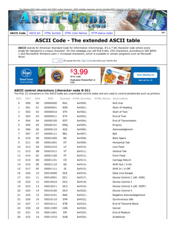
Appendix AASCII character codesASCII character codesCharacterDecHexCharacterDecHexCh
Logix 5000 Controllers ASCII Strings 2 Rockwell Automation Publication 1756- PM013H-EN-P - March 2022 Important User Information Read this document and the documents listed in the additional resources section about installation, configuration, and
