Transcription
Installation InstructionsSLC 500 BASIC and BASIC-T ModulesCatalog Numbers 1746-BAS and 1746-BAS-TInside . . .ForSee PageImportant User Information2Hazardous Location Considerations3Environnements dangereux3About the BASIC and BASIC-T Modules4Before You Begin5Install the 1746-BAS Module and 1746-BAS-TModule12Wire the PRT1 and PRT2 Communication Ports13Wire to the DH485 Port18Apply Power to your BASIC Module andBASIC-T Modules19Configure the BASIC Module and BASIC-TModule19Battery Replacement, Handling, Storage, andTransportation (Cat. No. 1747-BA)20Specifications24Additional Resources26Publication 1746-IN009B-EN-P - August 2005
2SLC 500 BASIC and BASIC-T ModulesImportant User InformationSolid state equipment has operational characteristics differing from those of electromechanical equipment.Safety Guidelines for the Application, Installation and Maintenance of Solid State Controls (PublicationSGI-1.1 available from your local Rockwell Automation sales office or online athttp://www.literature.rockwellautomation.com) describes some important differences between solid stateequipment and hard-wired electromechanical devices. Because of this difference, and also because of thewide variety of uses for solid state equipment, all persons responsible for applying this equipment mustsatisfy themselves that each intended application of this equipment is acceptable.In no event will Rockwell Automation, Inc. be responsible or liable for indirect or consequential damagesresulting from the use or application of this equipment.The examples and diagrams in this manual are included solely for illustrative purposes. Because of the manyvariables and requirements associated with any particular installation, Rockwell Automation, Inc. cannotassume responsibility or liability for actual use based on the examples and diagrams.No patent liability is assumed by Rockwell Automation, Inc. with respect to use of information, circuits,equipment, or software described in this manual.Reproduction of the contents of this manual, in whole or in part, without written permission of RockwellAutomation, Inc., is prohibited.Throughout this manual, when necessary, we use notes to make you aware of safety considerations.WARNINGIMPORTANTATTENTIONIdentifies information about practices or circumstances that can cause an explosion ina hazardous environment, which may lead to personal injury or death, propertydamage, or economic loss.Identifies information that is critical for successful application and understanding ofthe product.Identifies information about practices or circumstances that can lead to personal injuryor death, property damage, or economic loss. Attentions help you identify a hazard,avoid a hazard and recognize the consequences.SHOCK HAZARDLabels may be located on or inside the equipment (e.g., drive or motor) to alert peoplethat dangerous voltage may be present.BURN HAZARDLabels may be located on or inside the equipment (e.g., drive or motor) to alert peoplethat surfaces may be dangerous temperatures.Publication 1746-IN009B-EN-P - August 2005
SLC 500 BASIC and BASIC-T Modules3Hazardous Location ConsiderationsThis equipment is suitable for use in Class I, Division 2, Groups A, B, C, D ornon-hazardous locations only. The following WARNING statement applies to use inhazardous locations.ATTENTIONWARNING: EXPLOSION HAZARDSubstitution of components may impair suitability for Class I,Division 2.Do not replace components or disconnect equipment unlesspower has been switched off.Do not connect or disconnect components unless power has beenswitched off.All wiring must comply with N.E.C. article 501, 502, 503, and/orC.E.C. section 18-1J2 as appropriate.Environnements dangereuxCet équipement est conçu pour être utilisé dans des environnements de Classe I,Division 2, Groupes A, B, C, D ou non dangereux. La mise en garde suivantes’applique à une utilisation dans des environnements dangereux.ATTENTIONAVERTISSEMENT: DANGER D’EXPLOSIONLa substitution de composants peut rendre cet équipementimpropre à une utilisation en environnement de Classe 1, Division2.Ne pas remplacer de composants ou déconnecter l'équipementsans s'être assuré que l'alimentation est coupée.Ne pas connecter ou déconnecter des composants sans s'êtreassuré que l'alimentation est coupée.Publication 1746-IN009B-EN-P - August 2005
4SLC 500 BASIC and BASIC-T ModulesAbout the BASIC and BASIC-T ModulesThe BASIC module is a single-slot module that resides in a SLC 500 fixed ormodular controller chassis. The BASIC-T module is a higher speed version of theBASIC module with identical hardware features, including two configurable serialports for RS-232/423, RS-422, and RS-485 communication with I/O devices.Communication to an SLC 500 controller can take place across the 1746 I/Obackplane or on the DH485 network through the module’s DH485 port. Bothmodules also feature 24K bytes of battery-backed RAM, optional 8K or 32K bytenon-volatile memory modules, and multiple LED indicators for operator interface.TIPThe 1746-BAS module is compatible with the 1747-M1 and1747-M2 memory modules.The 1746-BAS module is also compatible with existing 1747-M3and 1747-M4 memory modules. The 1747-M3 and 1747-M4memory modules are no longer available for sale from RockwellAutomation.The 1746-BAS-T module is compatible with the 1771-DBMEM1and 1771-DBMEM2 memory modules.The modules can be programmed using an ASCII terminal or a personal computerequipped with 1747-PBASE BASIC development softwareTIPDue to the high speed of the 1746-BAS-T module, existingprograms written for the 1746-BAS module may requireadjustment for identical operation using the 1746-BAS-T module.Publication 1746-IN009B-EN-P - August 2005
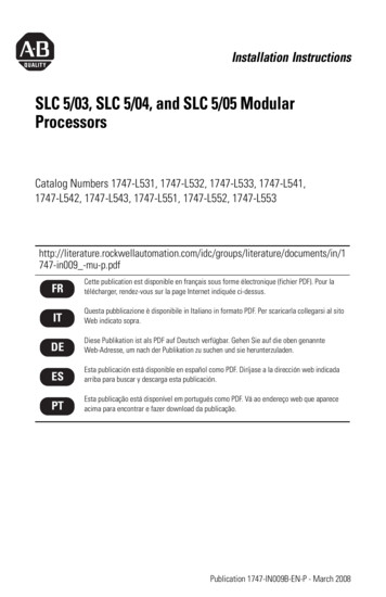
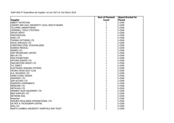
SLC 500 BASIC and BASIC-T Modules5Before You BeginBefore you begin to install the BASIC module and BASIC-T module, you need to: identify the communication ports, locate the LED indicators, and set the module jumpers.Identify the Communication PortsThere are three communication ports on the front of the BASIC module andBASIC-T module. They are: PRT1 PRT2 DH485The PRT1 port is used to interface the module with user devices. This port is aserial port that accommodates RS-232/423, RS-422, and RS-485 communicationmodes. Port PRT1 is capable of operating full-duplex at 300, 600, 1200, 2400, 4800,9600, and 19200 bps.The PRT2 port is used to interface the module with user devices or a modem usingDF1 protocol. This port is a serial port that accommodates RS-232/423, RS-422, andRS-485 communication modes. Port PRT2 is capable of operating full-duplex at 300,600, 1200, 2400, 4800, 9600, and 19200 bps.The DH485 port is used to interface the module with the DH485 network. This portis not isolated and cannot directly drive the DH485 network. You must use a1747-AIC link coupler to link port DH485 with the DH485 network.IMPORTANTWhen DF1 protocol is selected on port PRT2, DH485communications is disabled.Refer to Figure 1 for the location of the communication ports.Locate the LED IndicatorsThere are eight LED indicators on the front of the BASIC and BASIC-T modules.These LED indicators are used for module diagnostics and status indication. Refer toFigure 1 for the location of the LED indicators.Publication 1746-IN009B-EN-P - August 2005
6SLC 500 BASIC and BASIC-T ModulesFigure 1 Communication Ports and LED IndicatorsBASICACTBASICLEDs54321485FAULTBA LOWPR T1LED1PR cationACTGreenONThe module is receiving power from the backplane and isexecuting BASIC code.FlashingThe module is in Command mode.OFFThe module is not receiving power from the backplane. A faultcondition exists.ONPort DH485 on the module is active for communication.OFFPort DH485 on the module is not active for communication.FlashingPort PRT1 on the module is transmitting or receiving signals.OFFPort PRT1 on the module is not transmitting or receiving signals.FlashingPort PRT2 on the module is transmitting or receiving signals.OFFPort PRT2 on the module is not transmitting or receiving signals.ONA system problem was detected during background diagnostics.Contact your local Allen-Bradley representative.OFFNo system problems are detected during background diagnostics.ONThe voltage of the battery that backs up RAM is low. A newbattery is needed.OFFThe voltage of the battery that backs up RAM is at an acceptablelevel.ONUser definable. LED activated through the user program.OFFUser definable. LED de-activated through the user program.ONUser definable. LED activated through the user program.OFFUser definable. LED de-activated through the user program.485GreenPRT1GreenPRT2GreenFAULTRedBA LOWRedLED1AmberLED2AmberPublication 1746-IN009B-EN-P - August 2005
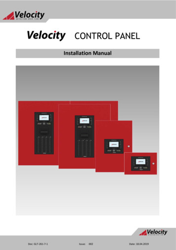
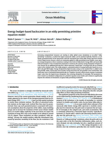
SLC 500 BASIC and BASIC-T Modules7Set the Module JumpersThe BASIC module and BASIC-T module have four sets of jumpers that you need toset. Jumpers JW1 and JW2 configure ports PRT1 and PRT2. Jumper JW3 configuresthe type of optional memory module. Jumper JW4 configures the program port.Figure 2 Jumper LocationsJW1CATFRNSERSLC 500BASIC MODULESERIAL NO.Memory Module54 3 2 1CONFIG9 87 654 3 2 1DF19 87 6JW3JW4DH485BatteryATTENTIONJW2Do not expose the module to surfaces or other areas that maytypically hold an electrostatic charge. Electrostatic charges canalter or destroy memory.Publication 1746-IN009B-EN-P - August 2005
8SLC 500 BASIC and BASIC-T ModulesATTENTIONSettings other than those shown for each jumper may causedamage to the module.Module Jumper JW1Use jumper JW1 to select one of the following configurations for port PRT1. RS-232/423 RS-422 RS-485Figure 3 Jumper JW1 Pin Assignments and SettingsPin Assignments2 4 6 8 10RS-4221 3 5 7 9RS-485RS-232/423 (Shipped Configuration)Publication 1746-IN009B-EN-P - August 2005
SLC 500 BASIC and BASIC-T Modules9Module Jumper JW2Use jumper JW2 to select one of the following configurations for port PRT2. RS-232/423 RS-422 RS-485Figure 4 Jumper JW2 Pin Assignments and SettingsRS-232/423 (Shipped Configuration)Pin Assignments9 7 5 3 1RS-48510 8 6 4 2RS-422Module Jumper JW3Use jumper JW3 to configure the memory module socket for one of the followingoptional memory modules.Memory ModuleMemory Size and TypeCompatible with1747-M18 K bytes EEPROM1746-BAS module1747-M232 K bytes EEPROM1746-BAS module1747-M3(1)8 K bytes UVPROM1746-BAS module1747-M4(1)32 K bytes UVPROM1746-BAS module1771-DBMEM18 K bytes EEPROM1746-BAS-T module1771-DBMEM232 K bytes EEPROM1746-BAS-T module(1)This memory module is no longer available for sale from Rockwell Automation. Existing1747-M3 and 1747-M4 memory modules are compatible with the 1746-BAS module and1746-BAS-T module.Publication 1746-IN009B-EN-P - August 2005
10SLC 500 BASIC and BASIC-T ModulesFigure 5 Jumper JW3 Pin Assignments and SettingsPinAssignments2 461 3 51747-M1 EEPROM1747-M2 EEPROM1747-M3 UVPROM(1)1771-DBMEM1 EEPROM1771-DBMEM2 EEPROM(Shipped Configuration)1747-M4 UVPROM(1)(1)This memory module is no longer available for sale from Rockwell Automation. Existing 1747-M3 and1747-M4 memory modules are compatible with the 1746-BAS module and 1746-BAS-T module.Module Jumper JW4Use jumper JW4 to select one of the following configurations for the module ports. PRT1 Port Program port with default communication settingsPRT2 Port ASCII interface portDH485 Port Run time DH485 operation only PRT1 Port ASCII interface portPRT2 Port ASCII interface portDH485 Port Program port with DH485 protocol PRT1 Port Program port with programmed communication settingsPRT2 Port ASCII interface portDH485 Port Run time DH485 operation only PRT1 Port Program port with programmed communication settingsPRT2 Port DF1 protocolDH485 Port DisabledIMPORTANTThe first setting shown in Figure 6 is the default configuration.When the jumper is set in this position, the module alwayspowers up in Command mode at 1200 bps, no parity, 8 data bits,and 1 stop bit.Publication 1746-IN009B-EN-P - August 2005
SLC 500 BASIC and BASIC-T ModulesIMPORTANT11When DF1 protocol is selected for port PRT2, port DH485 is notavailable for DH485 programming or run time operation.DF1 communication must be enabled through the BASICprogram.Figure 6 Jumper JW4 Pin Assignments and SettingsPin Assignments2 4 61 3 5PRT1 Port Program port with default communication settingsPRT2 Port ASCII interface portDH485 Port Run time DH485 operation onlyPRT1 Port ASCII interface portPRT2 Port ASCII interface portDH485 Port Program port with DH485 protocol(Shipped Configuration)PRT1 Port Program port with programmed communication settingsPRT2 Port ASCII interface portDH485 Port Run time DH485 operation onlyPRT1 Port Program port with programmed communication settingsPRT2 Port DF1 protocolDH485 Port DisabledPublication 1746-IN009B-EN-P - August 2005
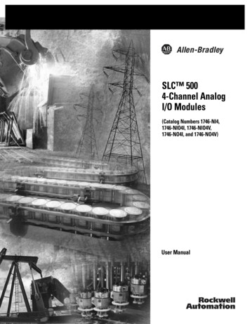
12SLC 500 BASIC and BASIC-T ModulesInstall the 1746-BAS Module and 1746-BAS-T ModuleYour BASIC module or BASIC-T module may be installed in any open slot of an SLC500 1746 I/O chassis except the first slot of the first chassis. The first slot is reservedfor the controller or adapter module. The BASIC module or BASIC-T module canalso be installed in an SLC fixed controller expansion chassis.ATTENTIONNever install, remove, or wire any module while power is applied.Also, do not expose the modules to surfaces or other areas thatmay typically hold an electrostatic discharge.Electrostatic discharge can damage integrated circuits orsemiconductors if you touch backplane connector pins.If the equipment is not installed and used as described in the SLC500 Modular Hardware Style User Manual, publication1747-UM011, the protection provided by the equipment may beimpaired.1. Turn off power to the chassis where you will insert the module.2. Align the circuit board of the module with the card guide of a slot (exceptslot 0) in the 1746 chassis.Figure 7 Module Location in the ChassisModule ReleaseCard Guide3. Slide the module in until the top and bottom retainer clips are secured.Publication 1746-IN009B-EN-P - August 2005
SLC 500 BASIC and BASIC-T Modules13Wire the PRT1 and PRT2 Communication PortsPorts PRT1 and PRT2 can communicate to user devices through RS-232/423, RS-422,and RS-485 communication modes. The communication mode you select dependson the setting of jumpers JW1 and JW2. Refer to the MODE command in the BASICReference Manual, publication 1746-RM001, for the default programming portconfiguration information.IMPORTANTWhen default communications are selected via JW4, the modulealways powers up in the Command mode at 1200 bps, no parity, 8data bits, and 1 stop bit.Pin AssignmentsUse these pin assignments to wire the mating connector of the cable used tointerface a user device to port PRT1 or PRT2. The sockets of this connector must bewired to correspond to the selected communication mode.PinRS-232/423RS-422RS-485IBM AT StandardRS-232 Signals1Note 1422 TXD -TRXD -DCD or CD2RXD422 RXD ONCOMMON6DSR422 RXD (3)DSR7RTS(2)(2)RTS8CTS(2)(2)CTS9(1)422 TXD TRXD RI(1)In RS-423 mode, these pins are still connected to their RS-422 loads. Do not use these pins in RS-423 mode.(2)In RS-422 and RS-485 modes, these pins are connected to their RS-423 drivers and receivers. Do not use these pins ineither RS-422 or RS-485 mode.(3)In RS-485 mode, these pins are still connected to their RS-422 receivers. Do not use these pins in RS-485 mode.Wiring diagrams for the RS-232/423 communication mode are shown starting onpage 16.Publication 1746-IN009B-EN-P - August 2005
14SLC 500 BASIC and BASIC-T ModulesHardware HandshakingThe module uses the following rules when hardware handshaking is enabled. Themodule: does not transmit until CTS (Clear to Send) becomes active, and examines DSR (Data Set Ready) following the receipt of a character.If DSR is active, the character is placed in the input queue. If DSR is inactive, thecharacter is assumed to be noise and is discarded.DTE and DCE OverviewIMPORTANTYou need to know whether the device connecting to the modulehas a DTE or DCE interface. Figures 8 through 12, starting onpage 16, are provided to help you make the appropriateconnection.DTE - Data Terminal EquipmentThe serial ports are configured as 9-pin Data Terminal Equipment (DTE), as aremost terminals or computer ports.DTE 9PinoutSignalDescriptionSignal from DTEPerspectivePin #DTE 25PinoutSignalDescriptionPin #1NC-No ConnectionInput82RXD-Received DataInput33TXD-Transmitted DataOutput24DTR-Data Terminal ReadyOutput205COM-Signal CommonShared76DSR-Data Set ReadyInput67RTS-Request to SendOutput48CTS-Clear to SendInput59NC-No ConnectionInput22Publication 1746-IN009B-EN-P - August 2005CD-Carrier DetectRI-Ring Indicator
SLC 500 BASIC and BASIC-T Modules15DCE - Data Communication EquipmentDevices such as modems are Data Communication Equipment (DCE). The pinoutson these terminals are defined for ease of interfacing with DTE equipment.DCE 9pinoutSignal DescriptionSignal from DCEPerspectivePin #DCE 25pinoutPin #1CD-Carrier DetectOutput82RXD-Received DataOutput33TXD-Transmitted DataInput24DTR-Data Terminal ReadyInput205COM-Signal CommonShared76DSR-Data Set ReadyOutput67RTS-Request to SendInput48CTS-Clear to SendOutput59RI-Ring IndicatorOutput22IMPORTANTAll signal directions listed in the previous two tables are valid. Forexample, TXD, Transmitted Data, is a DTE output but is also aDCE input. The signal description is the same for DTE and DCEbut the direction of the signal (perspective) has changed based onwhether you have a DTE or DCE device.Publication 1746-IN009B-EN-P - August 2005
16SLC 500 BASIC and BASIC-T ModulesFigure 8 RS-232/423 Wiring Diagram - 1746-BAS Module or 1746-BAS-T Moduleto a Modem (Hardware Handshaking Enabled)BASIC For DCE devices other than modems, connect the DSR of themodule with the DSR of the device. The CD signal of the device(other than a modem) is not used.IMPORTANTFigure 9 RS-232/423 Wiring Diagram - 1746-BAS Module or 1746-BAS-T Moduleto DTE Device (Hardware Handshaking Disabled)(2)(2)BASIC DTEDCE9-Pin25-Pin1N.C.DCD RTSCTSCTSRTS4820579N.C.GND(1)41(1) Connect to the shield of the cable.(2) Jumpers are only needed if you cannot disable the hardware handshaking on the port.(3) This is a N.C. for the 1747-KE module, 1746-BAS module, or 1746-BAS-T module.Publication 1746-IN009B-EN-P - August 2005(2)(2)
SLC 500 BASIC and BASIC-T Modules17Figure 10 RS-232/423 Wiring Diagram - 1746-BAS Module or 1746-BAS-T Moduleto Printer (Hardware Handshaking Enabled, Standard Printer Adapter Cable)(1)BASIC GND(2)1(1) The 1747-CP3 cable works in this application.(2) Connect to the shield of the cable.Figure 11 RS-422 Wiring DiagramBASICTXDRXDRXDTXD456COMRXD COMTXD 789TXD RXD 123Figure 12 RS-485 Wiring DiagramBASIC1 TRXD23TRXD-456COMCOM789 TRXD TRXD Publication 1746-IN009B-EN-P - August 2005
18SLC 500 BASIC and BASIC-T ModulesWire to the DH485 PortPort DH485 can communicate to user devices through the DH485 communicationmode. Use a 1747-C10 cable or 1747-C13 cable to connect the module to a linkcoupler interfaced with the DH485 network.Figure 13 Connecting the Module to a DH485 NetworkSLC 5/01, 5/02, and1747-AIC 5/03 Controller BASIC or BASIC-T ModuleLink CouplerTo DH485 Network1747-C10 or -C11 Cable1747-C13 CableSLC 5/04 or 5/05Controller1747-AICLink CouplerBASIC or BASIC-T ModuleTo DH485 Network1747-C10 or -C11 Cable1747-C13 CableIMPORTANTThe 1747-C13 cable acts only as a communication link and doesnot carry 24V dc power. Use a 1747-C10 cable or 1747-C11 cableto carry power from the controller to the link coupler, or from themodule to the link coupler.Publication 1746-IN009B-EN-P - August 2005
SLC 500 BASIC and BASIC-T Modules19Apply Power to your BASIC Module and BASIC-T ModulesOnce you have installed your BASIC module or BASIC-T module in your SLC 500chassis, you are ready to apply power to your SLC 500 system and beginprogramming.Configure the BASIC Module and BASIC-T ModuleYour BASIC module or BASIC-T module can be programmed using an ASCIIterminal or ASCII terminal emulation software. You can also use a personalcomputer with the BASIC Development Software (cat. no. 1747-PBASE). Use anASCII terminal to enter a BASIC program one line at a time. Use a personalcomputer with the BASIC development software to create a BASIC program that isthen downloaded to your module. Typical configurations are shown in Figure 14.Figure 14 Module ConfigurationsNull Modem Cableto RS-232 PortSLC 500 Controllerwith BASIC or BASIC-T ModuleASCII Terminal or PC withBASIC Development SoftwareInterface/ConverterRS-232 to RS-485Cat. No. 1747-PICSLC 500 Controllerwith BASIC or BASIC-T ModulePC withBASIC Development Software1747-C10 CablePublication 1746-IN009B-EN-P - August 2005
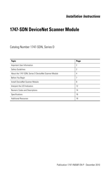
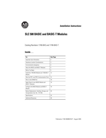
20SLC 500 BASIC and BASIC-T ModulesBattery Replacement, Handling, Storage, and Transportation(Cat. No. 1747-BA)Battery ReplacementYour module provides back-up power for RAM through a replaceable lithiumbattery (cat. no. 1747-BA). This battery provides back-up for approximately fiveyears. A BAT LOW indicator on the front of the module alerts you when the batteryvoltage has fallen below the replace battery threshold level.To replace the lithium battery:1. Remove power from the SLC 500 power supply module.ATTENTIONDo not remove the module from the SLC 500 chassis until allpower is removed from the SLC 500 power supply.2. Remove the module from the chassis by pressing the retainer clips at the topand bottom of the module.IMPORTANTIf the top or bottom retainer clips are broken while removing themodule from the chassis, they can be easily replaced. Pry off anybroken clips from the bottom with a screwdriver, if necessary. Donot twist off. Snap in the replacement clip. Order cat. no.1746-R15 (two per package).ATTENTIONDo not expose the module to surfaces or other areas that maytypically hold an electrostatic charge. Electrostatic charges canalter or destroy memory.Publication 1746-IN009B-EN-P - August 2005
SLC 500 BASIC and BASIC-T Modules21Figure 15 Battery LocationCATFRNSERSLC 500BASIC MODULESERIAL NO.54 3 2 1CONFIG9 87 654 3 2 1DF19 87 6DH485Red WIreWhite WIreLithium Battery3. Unplug the battery connector.IMPORTANTThe module has a capacitor that provides 30 minutes of batteryback-up while the battery is disconnected. Data in RAM is not lostif the battery is replaced within 30 minutes.4. Remove the battery from the retaining clips.5. Insert a new battery into the battery retaining clips.6. Plug the battery connector into the socket with the red lead wire on top andthe white lead wire on the bottom.7. Insert the module into the SLC 500 chassis.8. Restore power to the SLC 500 power supply.Battery HandlingATTENTIONDo not charge the batteries. An explosion could result or cellscould overheat causing burns.Do not open, puncture, crush, or otherwise mutilate the batteries.An explosion may result, exposing toxic, corrosive, or flammableliquids.Publication 1746-IN009B-EN-P - August 2005
22SLC 500 BASIC and BASIC-T ModulesBattery StorageStore the lithium batteries in a cool, dry environment, typically 20 C to 25 C( 68 F to 77 F) and 40% to 60% relative humidity.Battery TransportationOne or Two BatteriesYou can ship up to two batteries together within the United States withoutrestriction. Regulations governing shipment to or within other countries may differ.Three or More BatteriesProcedures for the transportation of three or more batteries shipped together withinthe United States are specified by the Department of Transportation (DOT) in theCode of Federal Regulations, CFR49, “Transportation.” An exemption to theseregulations, DOT - E7052, covers the transport of certain hazardous materialsclassified as flammable solids. This exemption authorizes transport of lithiumbatteries by motor vehicle, rail freight, cargo vessel, and cargo-only aircraft,providing certain conditions are met. Transport by passenger aircraft is notpermitted.Shipment of depleted batteries for disposal may be subject to specific regulation ofthe countries involved or to regulations endorsed by those countries, such as theIATA Restricted Articles Regulations of the International Air Transport Association,Geneva, Switzerland.IMPORTANTRegulations for transportation of lithium batteries are periodicallyrevised.ATTENTIONDo not incinerate or dispose of lithium batteries in general trashcollection. Explosion or violent rupture is possible. Batteriesshould be collected for disposal in a manner to prevent againstshort circuiting, compacting, or destruction of case integrity andhermetic seal.Publication 1746-IN009B-EN-P - August 2005
SLC 500 BASIC and BASIC-T Modules23For disposal, batteries must be packaged and shipped in accordance withtransportation regulations, to a proper disposal site. The U.S. Department ofTransportation authorizes shipment of “Lithium batteries for disposal” by motorvehicle only in regulation 173.1015 of CFR 49 (effective January 5, 1983). Foradditional information contact:U.S. Department of TransportationResearch and Special Programs Administration400 Seventh Street, S.W.Washington, D.C. 20590Although the Environmental Protection Agency at this time has no regulationsspecific to lithium batteries, the material contained may be considered toxic,reactive, or corrosive. The person disposing of the material is responsible for anyhazard created in doing so. State and local regulations may exist regarding thedisposal of these materials.For a lithium battery material safety data sheet, contact the manufacturer.Sanyo Energy Corporation600 Supreme DriveBensenville, IL 60106USAorTadarand Electronics2 Seaview Blvd.Port Washington, NY 11050USAPublication 1746-IN009B-EN-P - August 2005
24SLC 500 BASIC and BASIC-T ModulesSpecificationsBASIC and BASIC-T Modules SpecificationsSpecificationValuePower Supply Loading at 5V dc0.150 A (module only)0.150 A (module with link coupler)Power Supply Loading at 24V dc0.070 A (module only)0.125 A (module with link coupler)(2)Noise ImmunityNEMA Standard ICS 2-230VibrationDisplacement: 0.015 in, peak-to-peak at 5.57 HzAcceleration: 2.5 G at 57.2000 HzShock (operating)30 G(1)Port IsolationPort PRT1Port PRT2Port PRT1 to Port PRT2710V dc for 1 minute (backplane to port)710V dc for 1 minute (backplane to port)710V dc for 1 minute (port PRT1 to port PRT2)Ambient Temperature RatingOperating: 0. 60 C ( 32. 140 F)Storage: -40. 85 C (-40. 185 F)Humidity5.95% without condensationClock/Calendar Accuracy 1 minute/month at 25 C (77 F) 0, -6 minute/month at 60 C (140 F)(1)Port DH485 is not isolated.(2)If a Hand-Held Terminal, Data Table Access Module, or interface converter is connected to the link coupler, the additionalbackplane power draw of these components (listed on page 25) must be added to the 0.125 listed in the table above. Thisonly applies when the module is connected to the network via the link coupler and 1747-C10 cable or 1747-C11 cable. Thisdoes not apply when the 1747-C13 cable is used.CertificationsCertificationValueAgency Certificationc-UL-us listedClass I, Groups A, B, C or D, Division 2CE compliant for all applicable directivesC-Tick marked for all applicable actsPublication 1746-IN009B-EN-P - August 2005
SLC 500 BASIC and BASIC-T Modules25Operating Voltage and Current RequirementComponentOperating VoltageCurrent RequirementHand-Held Terminal24V dc0.105 AData Table Access Module24V dc0.104 AInterface Converter24V dc0.060 AIMPORTANTThe module receives its power from the SLC backplane. Thepower consumption of the module must be taken intoconsideration when planning your SLC 500 system. Refer to thedocumentation supplied with your SLC 500 fixed or modularcontroller for additional information on power supplies andcurrent requirements.CommunicationMaximum Distance Allowed in Meters (Feet)Rate (bps)RS-232RS-423RS-422RS-48530015 (50)1230 (4000)1230 (4000)1230 (4000)60015 (50)920 (3000)1230 (4000)1230 (4000)120015 (50)770 (2500)1230 (4000)1230 (4000)480015 (50)245 (800)1230 (4000)1230 (4000)960015 (50)120 (400)1230 (4000)1230 (4000)1920015 (50)60 (200)1230 (4000)1230 (4000)IMPORTANTUse the RS-423 jumper settings when communicating in RS-232mode.Publication 1746-IN009B-EN-P - August 2005
26SLC 500 BASIC and BASIC-T ModulesAdditional ResourcesForRefer to this documentPub. No.A more detailed description on howto install and use your modular SLC500 controller.SLC 500 Modular HardwareStyle User Manual1747-UM011A reference manual that containsstatus file data, instruction set, andtroubleshooting.SLC 500 Instruction SetReference Manual1747-RM001To view and download pdfs, go to Literature Library athttp://www.rockwellautomation.com/literature.To order printed copies, contact your Allen-Bradley Distributor or RockwellAutomation Sales Office.Publication 1746-IN009B-EN-P - August 2005
SLC 500 BASIC and BASIC-T Modules27Publication 1746-IN009B-EN-P - August 2005
Rockwell Automation SupportRockwell Automation provides technical information on the Web to assist you inusing its products. At http://support.rockwellautomation.com, you can findtechnical manuals, a knowledge base of FAQs, technical and application notes,sample code and links to software service packs, and a MySupport feature that youcan customize to make the best use of these tools.For an additional level of technical phone support for installation, configuration,and troubleshooting, we offer TechConnect Support programs. For moreinformation, contact your local distributor or Rockwell Automation representative,or visit http://support.rockwellautomation.com.Installation AssistanceIf you experience a problem with a hardware module within the first 24 hours ofinstallation, please review the information th
20 Specifications 24 Additional Resources 26. 2 SLC 500 BASIC and BASIC-T Modules . Installation and Maintenance of Solid State Controls (Publication SGI-1.1 available from your local Rockwell Automation sales office or online at . IMPORTANT Identifies information that is critical for successful application and understanding of the product.