Transcription
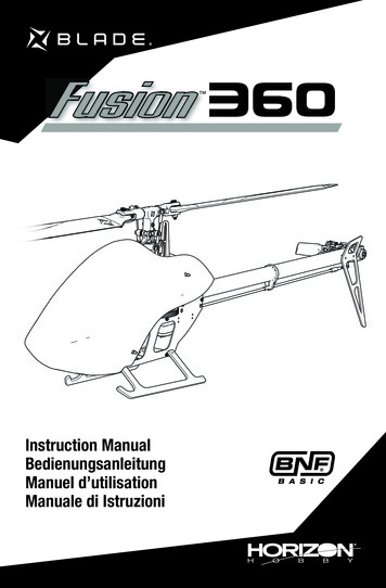
Instruction ManualBedienungsanleitungManuel d’utilisationManuale di Istruzioni
NOTICEAll instructions, warranties and other collateral documents are subject to change at the sole discretion of HorizonHobby, LLC. For up-to-date product literature, visit horizonhobby.com or www.towerhobbies.com and click on thesupport or resources tab for this product.Meaning of Special LanguageThe following terms are used throughout the product literature to indicate various levels of potential harm whenoperating this product:WARNING: Procedures, which if not properly followed, create the probability of property damage, collateral damage,and serious injury OR create a high probability of superficial injury.CAUTION: Procedures, which if not properly followed, create the probability of physical property damage AND apossibility of serious injury.NOTICE: Procedures, which if not properly followed, create a possibility of physical property damage AND a little or nopossibility of injury.WARNING: Read the ENTIRE instruction manual to become familiar with the features of the product beforeoperating. Failure to operate the product correctly can result in damage to the product, personal property andcause serious injury.This is a sophisticated hobby product. It must be operated with caution and common sense and requires some basicmechanical ability. Failure to operate this Product in a safe and responsible manner could result in injury or damageto the product or other property. This product is not intended for use by children without direct adult supervision. Donot use with incompatible components or alter this product in any way outside of the instructions provided by HorizonHobby, LLC. This manual contains instructions for safety, operation and maintenance. It is essential to read and followall the instructions and warnings in the manual, prior to assembly, setup or use, in order to operate correctly and avoiddamage or serious injury.Age Recommendation: Not for children under 14 years. This is not a toy.Safety Precautions and WarningsAs the user of this product, you are solely responsible for operating in a manner that does not endanger yourself andothers or result in damage to the product or the property of others. Always keep a safe distance in all directions around Never place any portion of the model in your mouth as ityour model to avoid collisions or injury. This model iscould cause serious injury or even death.controlled by a radio signal subject to interference from Never operate your model with low transmitter batteries.many sources outside your control. Interference can Always keep aircraft in sight and under control.cause momentary loss of control. Always move the throttle fully down at rotor strike. Always operate your model in open spaces away from Always use fully charged batteries.full-size vehicles, traffic and people. Always keep transmitter powered on while aircraft is Always carefully follow the directions and warningspowered.for this and any optional support equipment (chargers, Always remove batteries before disassembly.rechargeable battery packs, etc.). Always keep moving parts clean. Always keep all chemicals, small parts and anything Always keep parts dry.electrical out of the reach of children. Always let parts cool after use before touching. Always avoid water exposure to all equipment not Always remove batteries after use.specifically designed and protected for this purpose. Never operate aircraft with damaged wiring.Moisture causes damage to electronics. Never touch moving parts.WARNING AGAINST COUNTERFEIT PRODUCTS: If you ever need to replace a Spektrum component found ina Horizon Hobby product, always purchase from Horizon Hobby, LLC or a Horizon Hobby authorized dealer toensure authentic high-quality Spektrum product. Horizon Hobby, LLC disclaims all support and warranty with regards,but not limited to, compatibility and performance of counterfeit products or products claiming compatibility with DSM or Spektrum technology.EN2
Table of ContentsPost-Flight Inspections and Maintenance .10Advanced Tuning (Forward Programming) .11Advanced Tuning (Non-Forward Programming) .12Troubleshooting Guide.14Exploded View.15Parts List.17Recommended Parts List .17Optional Parts List .17Ball Bearing Sizes .17Limited Warranty .18Warranty and Service Contact Information.19FCC Information .19IC Information .20Compliance Information for the European Union .20First Flight Preparation .4Flying Checklist.4LED Indicator on Flight Controller .4Low Voltage Cutoff (LVC) .4Electronic Speed Controller Governor Operation .4Transmitter Setup .5Transmitter Setup .6Installing the Flight Battery.7Transmitter and Receiver Binding .7Throttle Hold .8Control Tests .8Pre-Flight Checklist .9Flying the Blade Fusion 360 .9Gyro Gain Adjustment.10Tail Belt Tension .10Specifications26.9 in (685mm)Main Rotor Diameter26.9 in (190mm)Tail Rotor Diameter32.2 oz (915 g)LengthHeightFlying WeightAirframeMotorsReceiverESCSwash ServosTail ServoBatteryChargerTransmitterComponentsBlade Fusion 360Brushless Out-Runner Motor, 1800Kv (BLH4731)Flight Controller/Receiver (SPMFC6250HX, SPM4649T)Brushless 60A ESC (BLHHW60A)Sub-Micro Digital Heli Cyclic MG Servo (SPMSH3055)Sub-Micro Digital Heli Tail MG Servo (SPMSH3065)Spektrum 6S, 22.2 V LiPo Battery, 1800mAh, 50C, IC3 (SPMX18006S50)Li-Po Balancing ChargerFull Range DSM2 /DSMX technology transmitter31.3 in (796mm)6.9 in (175mm)BNF nstalledRequiredRequiredRequiredBox Contents Blade Fusion 360 helicopterIf you own this product, you may berequired to register with the FAA.For up-to-date information on how toregister with the FAA, please visithttps://registermyuas.faa.gov/.For additional assistance on regulationsand guidance on UAS usage,visit knowbeforeyoufly.org/To receive product updates, special offers and more, register your product at www.horizonhobby.com3EN
First Flight PreparationFlying Checklist Remove and inspect contents Begin charging the flight battery (not included) Install the flight battery in the helicopter(once it has been fully charged) Program your computer transmitter Bind your transmitter Familiarize yourself with the controls Find a suitable area for flying Always turn the transmitter on firstPlug the flight battery into the lead from the ESCAllow the ESC to initialize and arm properlyVerify control directions and gyro compensations are correctFly the modelLand the modelUnplug the flight battery from the ESCAlways turn the transmitter off lastLED Indicator on Flight ControllerLED Indicator on FCIndicator DescriptionRed SolidFC6250HX waiting for receiver connection, system will not initialize until connectedYellow FlashCalibratingSlow Green FlashReady to FlySlow Red FlashFailsafe ActiveRed Solid and Yellow FlashCalibration Error, FC not level or is being moved during calibrationLow Voltage Cutoff (LVC)The ESC will continuously lower power to the motor untilcomplete shutdown when the battery reaches 12V underload. This helps prevent over-discharge of the Li-Po battery.Land immediately when the ESC activates LVC. Continuingto fly after LVC can damage the battery, cause a crash orboth. Crash damage and battery damaged due to overdischarge are not covered under warranty.Repeatedly flying the helicopter until LVC activates willdamage the helicopter battery.Disconnect and remove the Li-Po battery from the aircraftafter use to prevent trickle discharge. During storage, makesure the battery charge does not fall below 3V per cell.Electronic Speed Controller Governor OperationThe included electronic speed controller (ESC) utilizes ahead speed governor to maintain a constant head speedduring flight. The governor will work to maintain a constanthead speed throughout maneuvers and the discharge cycleof the flight battery.The throttle position determines the requested head speed,and although throttle curves are still used, they will be aconstant value; all positions of the curve are set to the samevalue. The lowest position of the normal flight mode throttlecurve must be set to 0 to ensure the motor can be disabled.ENThe default throttle curve settings listed in the transmittersetup tables should be acceptable to most pilots andwe recommend starting with these values. If you feelan adjustment is necessary after a few flights, adjustthe throttle percentage for the desired flight mode. Werecommend making small changes of 5% to find yourpreferred head speed.Remember the throttle position on the transmitter is simplyrequesting a specific head speed and this is not related tothe actual motor power percentage.4
Transmitter SetupSpektrum transmitters. The files for models using Spektrum transmitters with Spektrum AirWare software are alsoavailable for download online at www.spektrumrc.com.Program your transmitter before attempting to bind or flythe helicopter. Always start by creating a new model in thetransmitter to ensure no existing settings are inadvertentlyused. Transmitter programming values are shown below for theADJUST LISTDX6iSETUP LISTModel TypeSwash TypeHELI1 servo 90ReverseChannelAll ChannelsDirectionNModulation TypeAUTO DSMX-ENABLED/R COMBID/R SWAILETimerDown TimerSwitch4:00THR CUTTRAVEL ADJChannelAll ChannelsTravel100/100D/R & ExpoChannelAILE/ELEV/RUDDSw Pos01D/R10085Expo00Throttle CurveSwitch Pos (F Mode)NORMSTUNT*Pos 1080Pos 26080Pos 36080Pos 46080Pos 56080Pitch CurveSwitch Pos (F Mode)NORMSTUNTHOLDPos 125025Pos 2372537Pos 3505050Pos 4757575Pos 5100100100GYRORATESwitch Pos (F Mode)01SW-F.MODE82%75%NORMSTUNT01Mix 1GYRO GYRORATESWACTD 125%ELE D/RU 125%TRIM-INHDX7s, DX8FUNCTION LISTSYSTEM SETUPModel TypeHELISwash Type1 servo NormalF-Mode SetupFlight ModeF ModeHoldHoldSW SelectTrainerF ModeGyroMixHoldKnobFrame Rate11msDSMXAUX 2GearINHINHINHINHServo /R & ExpoSwitch Pos(Ail D/R)Chan DX7s DX8D/R ExpoAILE/00 100/100 0185/850ELEV/1285/850RUDDGyroNormalStunt 1HoldChannelSW75%75%75%GearF ModeThrottle CurveSwitch Pos (F Mode)DX7sDX8NN112HOLDHOLDPitch CurveSwitch Pos (F Mode)DX7sDX8NN112HOLDHOLDPt 24560750Pt 35060750Pt 45060750Pt 55060750Pt 130000Pt 240252525Pt 350505050Pt 475757575Pt 5100100100100TimerModeTimeStartOver5Pt 1060750Count Down3:00 ToneThrottle Out25%EN
Transmitter SetupDX6G2, DX6e, DX7G2, DX8G2, DX8e, DX9, iX12, DX18, DX20SYSTEM SETUPModel TypeSwash TypeHELINormalF-Mode SetupSwitch 1Switch BSwitch 2InhibitHold SwitchSwitch H10Channel AssignChannel Input Config1 Throttle2 Aileron3 Elevator4 Rudder5 GearINH6 Collective7 AUX 2*Frame Rate11ms*DSMX* Function is not available onall transmittersFUNCTION LISTServo D100/100GER100/100D/R & ExpoChan Sw (F) lStunt 1Stunt 2HoldChannelSwitchMixingP-Mix 5%GearFlight ModeNormalChannelsRateOffsetSwitchPositionGer Gyr125%/0%–100%Switch 100100/100Throttle CurveSw Pos(B)Pt 1N0165280Hold0Pitch CurveSw Pos(B)Pt 1N251020HOLD 25TimerModeTimeStartOverOne TimeReverseNormalNormalNormalNormalPt 26065800Pt 36065800Pt 4 Pt 560 6065 6580 8000Pt 237252537Pt 350505050Pt 475757575Pt 5100100100100Count Down5:00Throttle Out5%Inhibit
Installing the Flight Battery1. Lower the throttle.2. Power on the transmitter.3. Center all trims.4. To allow the ESC to arm and to keep rotors frominitiating at startup, turn on throttle hold and normalflight mode before connecting the flight battery.5. Attach hook material to the helicopter frame and loopmaterial to the battery.6. Install the flight battery on the helicopter frame. Securethe flight battery with a hook and loop strap. Connectthe battery cable to the ESC.CAUTION: Make sure the flight battery, wire andconnector does not come into contact with themotor. Failure to do so will cause the motor, ESC andbattery to overheat, resulting in a crash causing propertydamage and injury.7. Do not move the helicopter until the flight controllerinitializes. The swashplate will center, indicating thatthe unit is ready. The flight controller status LED willdisplay a slow green flash once initialization has beencompleted.8. The helicopter motor will emit a series of tones,indicating the ESC is armed.CAUTION: Always disconnect the Li-Po batteryfrom the ESC power lead when not flying to avoidover-discharging the battery. Batteries discharged belowthe lowest approved voltage may become damaged,resulting in loss of performance and potential fire whenbatteries are charged.Transmitter and Receiver BindingBinding is the process of programming the receiver to recognize the GUID (Globally Unique Identifier) code of a singlespecific transmitter. You need to ‘bind’ your chosen Spektrum DSM2 /DSMX technology equipped aircraft transmitterto the receiver for proper operation.Binding Procedure1. Program your transmitter using the Transmitter Setup found in this manual.2. Insert the bind plug in the BIND port on the wiring harness between the flight controller and the receiver.3. Connect the flight battery to the ESC. The orange LED on the receiver will begin flashing rapidly to indicate bind mode.4. Move the throttle stick to the low throttle position in normal mode.5. Follow the procedures of your specific transmitter to enter bind mode. The system will connect within a few seconds.Once connected, the orange LED on the receiver will come on solid orange.6. Disconnect the flight battery and remove the bind plug. Store the bind plug in a convenient place.NOTICE: Remove the bind plug to prevent the system from entering bind mode the next time the power is turned on.CAUTION: When using a Futaba transmitter with a Spektrum DSM2 module, you must reverse the throttle channel.If you encounter problems, obey binding instructions and refer to transmitter troubleshooting guide for other instructions.If needed, contact the appropriate Horizon Product Support office.7EN
Throttle HoldThrottle hold is used to prevent the motor from powering oninadvertently. For safety, turn throttle hold ON any time youneed to touch the helicopter or check the direction controls.Throttle hold is also used to turn off the motor quickly if thehelicopter is out of control, in danger of crashing, or both.The blades will continue to spin briefly when throttle hold isactivated. Pitch and direction control is still maintained.Control TestsCAUTION: You must complete the Tail Rotor and Cyclic tests prior to every flight. Failure to complete the testsand ensuring the sensor corrects in the proper direction can cause the helicopter to crash, resulting in propertydamage and injury.Tail Rotor1. Power on the transmitter.2. Turn TH HOLD ON and put transmitter in normal mode.3. Connect the flight battery to the ESC.4. Once Initialization is complete the LED on theFC6250HX will begin flashing green.5. Move the rudder stickto the right. The pitchslider on the tail shaftshould move towardthe tail case. If thepitch slider moves inthe opposite direction,ensure the rudderchannel reversesetting within the transmitter is set to normal.6. Release the rudder control. Manually turn the helicopternose to the left. The flight controller should compensateby moving the tail slider towards the tail case.CyclicWhen using a flybarless flight controller, you are controlling rotational rates while the SPMAR6250HX controls theservos. You are not directly controlling the servos with thetransmitter.It is normal for the swashplate to slowly move back toits original position after a stick input and for the servosto not move at the same speed as your control sticks.1. Tilt the helicopter forward. The swashplate must tiltbackward.2. Roll the helicopter left. The swashplate must roll right.Cyclic and Collective Control TestEnsure the throttle hold is ON when performing the direction control tests. Test the controls prior to each flight toensure the servos, linkages and parts operate correctly. If the controls do not react as shown in the illustrations below,confirm the transmitter is programmed correctly before continuing on to the Motor test.ElevatorLeft Side ViewLeft Side ViewElevator downAileronElevator upRear ViewRear ViewAileron leftENAileron right8
Collective PitchFront ViewFront ViewCollective pitch upCollective pitch downMotor TestPlace the helicopter outdoors on a clean, flat and levelsurface (concrete or asphalt) free of obstructions. Alwaysstay clear of moving rotor blades.1. Before you continue, confirm that TH HOLD is ON. Themotor will emit a series of tones after the helicopter’sESC has armed properly.WARNING: Stay at least 30 feet (10 meters) awayfrom the helicopter when the motor is running. Donot attempt to fly the helicopter at this time.2. Ensure the throttle is lowered completely. Confirmthe transmitter is still set to normal flight mode. Turnthrottle hold OFF to enable throttle control. Slowlyincrease the throttle until the blades begin to spin. Themain blades spin clockwise when viewing the helicopterfrom the top. The tail rotor blades spin counterclockwisewhen viewing the helicopter from the right-hand side.WARNING: The motor will spin when the throttle isincreased while TH HOLD is OFF.Pre-Flight Checklist Check all screws and ensure that they are tight Check belt tension and ensure that it is not too tight ortoo loose Check main and tail blades to ensure they are not damaged Check all links and make sure they move freely but donot pop off easily Check that the transmitter and flight batteries are fullycharged Check all wires to ensure that they are not cut, pinched,or chaffed and are properly secured Check all wire connections Check gears and make sure no teeth are missing Make sure flight battery is properly secured Make sure the receiver is properly secured Perform a complete control test Verify the flight controller is correcting in the proper directions Check that servos are functioning properlyFlying the Blade Fusion 360Consult local laws and ordinances before choosing a location to fly your aircraft.Select a large, open area away from people and objects.LandingYour first flights should be outdoors in low-wind conditions.Establish a low level hover. Deliberately lower the throttleAlways stay at least 30 feet (10 meters) away from theuntil the helicopter lands.helicopter when it is flying.When the helicopter is in stunt mode:The Blade Fusion 360 is intended to be flown outdoors by The rotor head speed is constant.experienced pilots. The main rotor will increase negative pitch as theTakeoffthrottle/collective stick is moved from the middle stickDeliberately increase throttle and establish a hoverposition to the low stick position. Negative pitch allowsat least 24” (0.6 meter) high, outside of ground effect.the helicopter to fly upside down and perform aerobatics.CAUTION: Making large inputs to the roll or pitchChange between stunt and idle up modes in a hover withcontrols while the helicopter is on the groundthe throttle near the hovering stick position.may result in a crash.WARNING: Do not use wooden main blades withFlyingthe Blade Fusion 360. Injury and/or propertyThe helicopter lifts off the ground when the rotor headdamage could occur. Only use Blade Fusion 360reaches a suitable speed. Establish a low-level hover toreplacement carbon fiber main blades.verify proper operation of your helicopter.First flights should be performed in normal mode and lowcyclic and rudder dual rates until you are familiar with theflying manner of the Blade Fusion 360.CAUTION: Always fly the helicopter with your back tothe sun and the wind to prevent loss of flight control.9EN
Gyro Gain Adjustment If the tail wags or oscillates, lower the gain on the gyro.In the transmitter gyro menu, decrease the gyro gainvalues a small amount at a time until the helicopter isstable within a particular flight mode. If the tail is drifting while hovering, increase the gain on the gyro.In the transmitter gyro menu, increase the gyro gainvalues a small amount at a time until the tail starts towag/oscillate. Afterwards, reduce the gain until the tailstops wagging/oscillating within a particular flight mode.Tail Belt TensionBelt tension that is too tight results in loss of power and causes the belt to wear more quickly. Tension that is too loosecan cause belt damage and loss of tail rotor control in flight.To check for proper belt tension:1. View the tail rotor drive belt through the opening at theback of the main frame.2. Use a hex wrench or standard screwdriver to compress thebelt through the opening.3. Apply light pressure on the belt, compressing the belttoward the left side of the tail boom.4. The belt tension is correct if the compressed side ofthe belt reaches approximately halfway to the oppositeside of the belt.a. If the compressed side of the belt reaches fartherthan halfway to the other side of the belt, the tensionis too loose.b. If the compressed side of the belt does not reach halfway to the other side of the belt, the tension is too tight.To adjust belt tension:1. Loosen the two screws at the back of the main frame.2. Slide the boom forward or aft to adjust the belt tension.3. When the belt tension is properly adjusted, tighten thetwo screws at the back of the frame.Post-Flight Inspections and MaintenanceBall LinksCleaningMake sure the plastic ball link holds the control ball, but is not tight (binding) on the ball. When a linkis too loose on the ball, it can separate from the ball during flight and cause a crash. Replace wornball links before they fail.Make sure the battery is not connected before cleaning. Remove dust and debris with a soft brushor a dry lint free cloth.BearingsReplace bearings when they become damaged.WiringMake sure wiring does not block moving parts. Replace damaged wiring and loose connectors.Make sure there are no loose screws, other fasteners or connectors. Do not over tighten metal screwsin plastic parts. Tighten screw so parts are mated together, then turn screw only 1/8th of a turn more.Make sure there is no damage to rotor blades and other parts which move at high speed. DamageRotorsto these parts includes cracks, burrs, chips or scratches. Replace damaged parts before flying.Make sure the flight controller is securely attached to the frame. Replace the double-sided tapeFlight Controllerwhen necessary. The helicopter will crash if the flight controller separates from the helicopter frame.FastenersEN10
Advanced Tuning (Forward Programming)Applies to forward programming capable Spektrum Transmitters includingDX6G2, DX7G2, DX8G2, DX9, iX12, DX18, DX20The Fusion 360 default settings are appropriate for most users. We recommend flying with the default parameters beforemaking any adjustments.The Fusion 360 BNF flight controller may be programmed from any compatible Spektrum transmitter(visit SpektrumRC.com for more information).The flight controller shipped with BNF models has a range of adjustable parameters suitable for the Fusion 360 Helicopterand is not intended for use in other aircraft.It is important to use the included servos with the BNF flight controller because the adjustable parameters available forthe SPMAR6250HX are designed around the recommended servos. It is possible there may not be enough range for thehelicopter to be tuned when using alternative servos.Entering the Advanced Parameters MenuWith the helicopter bound to the transmitter and powered on, enter the Function List and select Forward Programming.The list of adjustable parameters and the range of values available for tuning have been tailored for this helicopter. Makesmall changes to one parameter at a time and test fly the changes before changing the parameter further or changing adifferent parameter.Calibration Procedure:If the helicopter is experiencing drift issues, perform the following calibration. The calibration procedure may also beneeded following crash repairs.8. Select System Setup.1. Ensure the surface used for calibration is level.9. Select Calibration.2. Power on the transmitter and activate throttle hold.10. Select Apply and the calibration will begin. The3. Connect the flight batter to the ESC and allowing theLED will flash yellow indicating the calibration ismodel to initialize.proceeding normally. If the LED changes to red this4. Turn Throttle Hold ON.indicates the model is not near level or the model was5. Using a bubble level as shown below, level themoved, in this case the calibration starts over.helicopter by placing a shim under the landing skid.11. After the calibration is successfully completed, thereceiver LED will will change to a slow green flashwhich indicates the calibration has completed.12. Proceed to the pre-flight check list procedure beforeBubble levelflying your model.Shim6. Enter the Function List on your transmitter.7. Select Forward Programming.Factory ResetIf the process of tuning the Fusion 360 helicopter results in undesirable flight performance, you can reset the settingsback to factory defaults by selecting the Factory Reset option in Forward Programming.1. Enter the Function List5. Select Apply2. Select Forward Programming6. Perform the Setup- Swashplate- Sub Trim functionand ensure the servos are properly trimmed.3. Select System Setup7. Proceed with the pre-flight check list procedure4. Select Factory Resetbefore flying the model.11EN
Advanced Tuning (Non-Forward Programming)Applies to Spektrum transmitters not capable of forward programing includingDX6i, DX6e, DX7s DX8, and DX8eYour Blade Fusion 360 was setup at the factory and testflown. The servo adjustment steps are usually only necessary in special circumstances, such as after a crash or if aservo or linkage is replaced.For pilots flying with a transmitter not capable of forwardprogramming use the following procedures to make servoadjustments and perform the calibration procedure.The advanced tuning options must be entered within 30 seconds after initialization completes. In addition the combination of dual rates and travel adjustments must result in a throw greater than 65% in order to enter the tuning modes.Entering Servo Adjustment Mode1. Lower the throttle stick to the lowest position.2. Power ON the transmitter and activate throttle hold.3. Install the flight battery on the helicopter frame,securing it with the hook and loop strap.4. Connect the battery connector to the ESC.5. After initialization is complete (indicated by a slowgreen flash), hold the left stick to the bottom left cornerand the right stick to the bottom right corner as shown.Swashplate LevelingBefore saving your adjustments and exiting servoadjustment mode, verify the swashplate is level and bothmain rotor blades are at 0 degrees pitch.If they are not, make linkage adjustments as necessary.Saving the Servo Adjustments1. Lower the throttle stick to the lowest position andrelease the sticks.2. Move the tail rotor stick to the left and hold for fourseconds to exit Servo Adjustment Mode. The servos willjump indicating a return to normal operation.3. Release the tail rotor stick.4. Perform the pre-flight checklist procedure before flyingyour model.6. Servo Adjustment Mode is indicated by the swashplateservos jumping and then slowly moving back to center.7. Release the sticks and proceed to the next step.Adjusting the Servo Neutral PositionWith the model in Servo Adjustment Mode, the control stickand gyro inputs are disabled and the servos are held in theneutral position. Check the position of the servo arms toverify they are perpendicular to the servos. If the arms are perpendicular to the servos, no adjustment is necessary.Exit Servo Adjustment Mode. If one or more servo arm is not perpendicular to theservos, continue the servo adjustment process.While watching the swashplate servos, apply fore or aftcyclic and release. One of the servos will jump, indicatingthe selected servo. Apply fore or aft cyclic and release untilthe servo that needs to be adjusted is selected.Once the servo you wish to adjust is selected, move thecyclic stick left or right to adjust the servo neutral positionin the desired direction.To reset the current servo to the default neutral position, holdthe rudder stick full right for two seconds.The range of adjustment is limited. If you are unable toadjust the servo arm to be perpendicular to the servo, youmust reset the servo to the default neutral position, removethe servo arm and place it back onto the servo as close toperpendicular as possible. You may then adjust the servoneutral position using left or right cyclic stick.EN12Control Input in ServoAction in ServoAdjustment ModeAdjustment ModeSelect Previous or Next ServoFore/Aft CyclicIncrease or Decrease SubRight/Left CyclicTrim AdjustmentHold For Two Seconds;Right TailrotorNeutral Position is Reseton Selected ServoLeft Tailrotor and Low Hold for Four Seconds; ExitthrottleServo Adjustment mode
Calibration ProcedureIf the helicopter is experiencing d
3 EN Components BNF Basic Airframe Blade Fusion 360 Included Motors Brushless Out-Runner Motor, 1800Kv (BLH4731) Installed Receiver Flight Controller/Receiver (SPMFC6250HX, SPM4649T) Installed ESC Brushless 60A ESC (BLHHW60A) Installed Swash Servos Sub-Micro Digital Heli Cyclic MG Servo (SPMSH3055) Installed Tail Servo Sub-Micro Digital Heli Tail MG Servo (SPMSH3065) Installed

