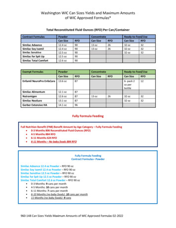
Transcription
Instruction ManualBedienungsanleitungManuel d’utilisationManuale di IstruzioniRTFREADY-TO-FLY
NOTICEAll instructions, warranties and other collateral documents are subject to change at the sole discretion of HorizonHobby, LLC. For up-to-date product literature, visit horizonhobby.com and click on the support tab for this product.Meaning of Special LanguageThe following terms are used throughout the product literature to indicate various levels of potential harm whenoperating this product:NOTICE: Procedures, which if not properly followed, create a possibility of physical property damage AND a little or nopossibility of injury.CAUTION: Procedures, which if not properly followed, create the probability of physical property damage AND apossibility of serious injury.WARNING: Procedures, which if not properly followed, create the probability of property damage, collateral damage,and serious injury OR create a high probability of superficial injury.WARNING: Read the ENTIRE instruction manual to become familiar with the features of the product beforeoperating. Failure to operate the product correctly can result in damage to the product, personal property andcause serious injury.This is a sophisticated hobby product. It must be operated with caution and common sense and requires some basicmechanical ability. Failure to operate this Product in a safe and responsible manner could result in injury or damageto the product or other property. This product is not intended for use by children without direct adult supervision. Donot use with incompatible components or alter this product in any way outside of the instructions provided by HorizonHobby, LLC. This manual contains instructions for safety, operation and maintenance. It is essential to read and followall the instructions and warnings in the manual, prior to assembly, setup or use, in order to operate correctly and avoiddamage or serious injury.Age Recommendation: Not for children under 14 years. This is not a toy.Safety Precautions and Warnings Always keep a safe distance in all directions aroundyour model to avoid collisions or injury. This model iscontrolled by a radio signal subject to interference frommany sources outside your control. Interference cancause momentary loss of control. Always operate your model in open spaces away fromfull-size vehicles, traffic and people. Always carefully follow the directions and warnings forthis and any optional support equipment(chargers, rechargeable battery packs, etc.). Always keep all chemicals, small parts and anythingelectrical out of the reach of children. Always avoid water exposure to all equipment notspecifically designed and protected for this purpose.Moisture causes damage to electronics. Never place any portion of the model in your mouth as itcould cause serious injury or even death.EN Never operate your model with low transmitterbatteries. Always keep aircraft in sight and under control. Always move the throttle fully down at rotor strike. Always use fully charged batteries. Always keep transmitter powered on while aircraft ispowered. Always remove batteries before disassembly Always keep moving parts clean. Always keep parts dry. Always let parts cool after use before touching. Always remove batteries after use. Never operate aircraft with damaged wiring. Never touch moving parts.2
Table of ContentsFirst Flight Preparation .4Flying Checklist .4Charging Warnings.4Installing the Landing Gear .5Installing the Transmitter Batteries (RTF) .5Installing the Flight Battery .5Transmitter and Receiver Binding.6SAFE Technology .7Transmitter Control .7Flight Mode and Rate Selection .8Transmitter Setup Table .9LED Codes .12Understanding the Primary Flight Controls .12Flying the 180 QX HD .13Post-Flight Inspection and Maintenance Checklist .13Operating the Camera .13Flight Mode Calibration .14Troubleshooting Guide .15Exploded View .16Parts Listings .16Optional Parts .17Limited Warranty .17Warranty and Service Contact Information .18FCC Information .18IC Information .18Compliance Information for the European Union .19Blade 180 QX HD FeaturesAirframe – Blade 180 QX HDMotors – 8.5mm BrushedOn-board Electronics – 5-in-1 mixer/ESCs/GyroBattery – 500mAh 1S 3.7V 25C Li-PoCharger – 1S USB Li-Po Charger, 500 mAh, JSTTransmitter – MLP6DSM SAFE cludedIncludedLengthHeightPropeller dedRequiredBlade 180 QX HD Specifications3.35 oz (95 g)13.98 in (355mm)Flying Weight3.15 in (80mm)To register your product online,visit www.bladehelis.com5.35 in (136mm)Box Contents Blade 180 QX HD 720p Digital Video Camera with Still Capability 1S 3.7V 25C 500mAh Li-Po Battery 1S USB Li-Po Charger MLP6DSM SAFE Transmitter (RTF Only) 4 AA Batteries (RTF Only)3EN
First Flight PreparationFlying Checklist Remove and inspect contents Begin charging the flight battery Install the flight battery in the quadcopter(once it has been fully charged) Program your computer transmitter (BNF only) Bind your transmitter (BNF only) Familiarize yourself with the controls Find a suitable area for flying Always turn the transmitter on first Plug the flight battery into the lead from the 5-in-1control unit Allow the 5-in-1 control unit to initialize and armproperly Fly the model Land the model Unplug the flight battery from the 5-in-1 control unit Always turn the transmitter off lastCharging WarningsThe Battery Charger (EFLC1010) included with yourquadcopter has been designed to safely charge the Li-Pobattery. Always charge batteries away from flammable materials. Always inspect the battery before charging. Always disconnect the battery after charging, and let thecharger cool between charges. Always constantly monitor the temperature of the batterypack while charging. ONLY USE A CHARGER SPECIFICALLY DESIGNED TO CHARGELI-PO BATTERIES. Failure to charge the battery with acompatible charger may cause a fire resulting in personalinjury and/or property damage. Never discharge Li-Po cells to below 3V under load. Never cover warning labels with hook and loop strips. Never leave charging batteries unattended. Never charge batteries outside recommended levels. Never charge damaged batteries. Never attempt to dismantle or alter the charger. Never allow minors to charge battery packs. Never charge batteries in extremely hot or cold places(recommended between 40–120 F or 5–49 C) or place indirect sunlight.CAUTION: All instructions and warnings must befollowed exactly. Mishandling of Li-Po batteries canresult in a fire, personal injury and/or property damage. By handling, charging or using the included Li-Po battery,you assume all risks associated with lithium batteries. If at any time the battery begins to balloon or swell,discontinue use immediately. If charging or discharging,discontinue and disconnect. Continuing to use, charge ordischarge a battery that is ballooning or swelling can resultin fire. Always store the battery at room temperature in a dry areafor best results. Always transport or temporarily store the battery in a temperature range of 40–120º F (5–49 C). Do not store batteryor model in a car or direct sunlight. If stored in a hot car, thebattery can be damaged or even catch fire.Battery ChargingNOTICE: Charge only batteries that are cool to the touchand are not damaged. Look at the battery to make sure itis not damaged e.g., swollen, bent, broken or punctured.1. Insert the charger into a USB port.2. Properly connect the battery to the charger lead.3. Always disconnect the flight battery from the chargerimmediately upon completion of charging.CAUTION: Only use chargers specificallydesigned to charge the included Li-Po battery.Failure to do so could result in fire, causing injury orproperty damage.CAUTION: Never exceed the recommendedcharge rate.SOLID RED LED–ChargingLED OFF–ChargeCompleteDC Input:5.0V 500mADC Output:4.2V 500mA EFLC1010USB Li-PoChargerLED IndicationsWhen you make the connection successfully, the LED on the charger turns solid red, indicating charging has begun.Charging a fully discharged (not over-discharged) 500mAh battery takes approximately 60 minutes. The light goes outwhen the charge is complete.CHARGING (Solid Red)MAX CHARGE (OFF)CAUTION: Once charging is complete, immediately remove the battery. Never leave a battery connected to thecharger.EN4
Installing the Landing GearInstall the landing gear using thefour included screws.Installing the Transmitter Batteries (RTF)Replace the transmitter batteries when the power LED flashes and thetransmitter beeps.Installing the Flight Battery12341. Lower the throttle to the lowest setting.2. Power on the transmitter.3. Install the battery by sliding it into the battery mounting slot below the 5-in-1 control unit. Slide the battery into theslots with the label facing upward so that the battery key molded into the battery end-cap comes in contact withthe key on the battery slot.4. Connect the battery cable to the 5-in-1 control unit.5. Place the quadcopter on its skids on a flat surface and leave the aircraft still until the LED on the 5-in-1 control unitindicates one of the following flight modes:Solid blue: Stability, Low-angle modeSlow blue flashing: Stability, High-angle modeSolid red: Agility modeIf the LED is rapidly flashing blue, see the Transmitter and Receiver Binding section.CAUTION: Always disconnect the Li-Po battery from the aircraft when not flying to avoid over-discharging thebattery. Batteries discharged to a voltage lower than the lowest approved voltage may become damaged,resulting in loss of performance and potential fire when batteries are charged.5EN
Transmitter and Receiver BindingTo bind or re-bind your quadcopter to your chosen transmitter, please follow the directions below.General Binding Procedure1. Disconnect the flight battery from the quadcopter.2. Select a clean model memory on your transmitter (computer radios only).3. Select Acro or Airplane model type on your transmitter.4. Make sure all servo reversing is set to Normal on your transmitter.5. Center all trims on your transmitter.6. Power off the transmitter and move all switches to the 0 position. Move the throttle to the low/off position.7. Connect the flight battery in the quadcopter. The blue LED on the 5-in-1 control unit flashes after 5 seconds.8. Put the transmitter into bind mode while powering on the transmitter.9. Release the bind button/switch after 2–3 seconds. The quadcopter is bound when the blue LED on the5-in-1 control unit turns solid.10. Disconnect the flight battery and power the transmitter off.CAUTION: When using a Futaba transmitter with a Spektrum DSM2 /DSMX module, you must reverse thethrottle channel and re-bind. Refer to your Spektrum module manual for binding and failsafe instructions.Refer to your Futaba transmitter manual for instructions on reversing the throttle channel.RTFYour RTF transmitter comes prebound to the model. If you need to re-bind, follow the directions below.MLP6DSM Binding Procedure1. Disconnect the flight battery from the quadcopter.2. Center all trims on your transmitter.3. Power off the transmitter and move the throttle stick to the down/off position.4. Connect the flight battery in the quadcopter. The LED on the 5-in-1 control unit flashes after 5 seconds.5. When the blue light is flashing, push in and hold down the left stick* while powering on the transmitter(you will hear a ‘click’).6. Release the left stick. The transmitter will beep and the power LED will blink.7. The quadcopter is bound when the LED on the 5-in-1 control unit is solid blue (not blinking).8. Disconnect the flight battery and power the transmitter off.* The trigger switch may also be used for the binding procedure.If you encounter problems, obey binding instructions and refer to the troubleshooting guide for other instructions.If needed, contact the appropriate Horizon Product Support office. For a list of compatible DSM transmitters, pleasevisit www.bindnfly.com.EN6
TechnologyRevolutionary SAFE (Sensor Assisted Flight Envelope) technology uses an innovative combination of multi-axis sensorsand software that allows model aircraft to know its position relative to the horizon. This spatial awareness is utilized to createa controlled flight envelope the aircraft can use to maintain a safe region of bank and pitch angles so you can fly more safely.Far beyond stability, this level of protection offers multiple modes so the pilot can choose to develop his or her skills with agreater degree of security and flight control that always feels crisp and responsive.SAFE technology delivers: Flight envelope protection you can enable at the flip of a switch. Multiple modes let you adapt SAFE technology to your skill level instantly.Best of all, sophisticated SAFE technology doesn’t require any work to enjoy. Every aircraft with SAFE installed is ready to useand optimized to offer the best possible flight experience.FlySAFERC.comTransmitter ControlRTFCaCamera trigger(b(bind switch)Flight modeswitchADual rateswitchBind switchHGBCFDEWhen pressed down, trim buttons make a sound that increases or decreases in pitch at each pressing. The middle orneutral trim position is heard as a middle tone in the pitch range of the sounds. The end of the control range is soundedby a series of beeps.ABCDEFGHMode 1Power LED/flight modeindicatorAileron (Left/Right)Throttle TrimElevator TrimRudder (Left/Right)Elevator (Up/Down)Mode 2Power LED/flight modeindicatorAileron (Left/Right)Elevator (Up/Down)Elevator udder (Left/Right)Throttle (Up/Down)7EN
Flight Mode and Rate SelectionRTFChange flight modes by moving the three-position flight mode switch. Ensurethe flight mode switch is in the desired position before flying. In stability low angle mode (switch position 0), the controls provide aminimum bank angle. This mode is shown by the flight control board onthe quadcopter glowing solid blue. In stability high angle mode (switch position 1), the controls provide for amaximum bank angle. This mode is shown by the flight control board onthe quadcopter slowly flashing blue. Agility mode (switch position 2) is shown by the flight control board onthe quadcopter glowing solid red.When powered on, this transmitter is automatically in high-rate mode.Change rates by pressing and releasing the right control stick. In low-rate mode, the controls cannot reach their maximum values. In high-rate mode, the controls can reach their maximum values.If you purchased a BNF 180 QX HD, the channel 5 switch on your transmitter will select flight modes. When the LED onthe control board is solid blue, the flight mode is set to stability low angle mode. When the LED is slowly blinking blue,the quadcopter is in stability high angle mode. When the light is solid red, the quadcopter is in agility mode. See theTransmitter Setup Table for specific setup information.EN8
9N/ADX4e (New)w/ 3 Position N/ASwitchN/ADX4e (Old)w/ 2 Position N/ASwitchN/AN/AN/AMLP6DSMDX5e (Old)w/ 2 Position N/ASwitchModel ReverseTypeSetupTransmitterN/AN/AN/AN/AMode SetupChannel 5 (2) Agility ModeChannel 5 (1) Stability Mode, HighAngleChannel 5 (0) Stability Mode, LowAngleChannel 5 (1) Agility ModeStill Mode(Default)Press Trainer Take PictureVideo ModePress Trainer Start/Stop RecordingPress & Hold Trainer for 4 Seconds Change ModesStill Mode(Default)Press Trainer Take PictureVideo ModePress Trainer Start/Stop RecordingPress & Hold Trainer for 4 Seconds Change ModesChannel 5 (0) Stability Mode,Low AngleACT/AUX (ON) Agility ModeStill Mode(Default)Press Trainer Take PictureVideo ModePress Trainer Start/Stop RecordingPress & Hold Trainer for 4 Seconds Change ModesStill Mode(Default)Press Trainer Take PictureVideo ModePress Trainer Start/Stop RecordingPress & Hold Trainer for 4 Seconds Change ModesCamera OperationACT/AUX (OFF) Stability Mode,Low AngleChannel 5 (2) Agility ModeChannel 5 (1) Stability Mode,High AngleChannel 5 (0) Stability Mode,Low AngleSwitch PositionsRateRateRateRateDualRateSwitchLowRate100% 70%Fixed Fixed100% 70%Fixed Fixed100% 70%Fixed Fixed100% 70%Fixed FixedHighRateTransmitter Setup TableEN
EN10AcroAcroDX7/7SEDX7STravel Adj:GEAR (0) 100%; GEAR (1) 40%MIX 1: FLAP Gear OFF/ONFLAP - R (6)RATE -50%All Others - N0%SW:MIXOFFSET: 0Switch Select:Trainer to Aux 1; F Mode to GearSet All Others to InhMIX 1:GER GERAUX1 - RRATE:0%All Others - N-100%OFFSET:0%;TRIM:InhSW:Mix0DX6iAcroTravel Adj:GEAR (0) 100%; F MODE (1) 40%FLAPS:Norm 100; LAND 100GEAR - RMIX 1: ACT; Gear Gear ACTAll Others - NRATE D 0%U 100%SW MIXTRIM INHN/AMode SetupN/AModel ReverseTypeSetupDX5e (New)w/ 3 Position N/ASwitchTransmitterF MODE (1); HOLD (1) Agility ModeF MODE (1) Stability Mode,High AngleF MODE (0) Stability Mode,Low AngleGEAR (1); Mix (1) Agility ModeGEAR (1); Mix (0) Stability Mode,High AngleGEAR (0); Mix (0) Stability Mode,Low AngleGEAR (1); Mix (1) Agility ModeGEAR (1); Mix (0) Stability Mode,High AngleGEAR (0); Mix (0) Stability Mode,Low AngleChannel 5 (2) Agility ModeChannel 5 (1) Stability Mode, HighAngleChannel 5 (0) Stability Mode, LowAngleSwitch PositionsStill Mode(Default)Press Trainer Take PictureVideo ModePress Trainer Start/Stop RecordingPress & Hold Trainer for 4 Seconds Change ModesStill Mode(Default)FLAP 0-1-0 Take PictureVideo ModeFLAP 0-1-0 Start/Stop RecordingFLAP Pos 0-1(4 Seconds)-0 ChangeModesStill Mode(Default)FLAP 0-1-0 Take PictureVideo ModeFLAP 0-1-0 Start/Stop RecordingFLAP Pos 0-1(4 Seconds)-0 ChangeModesStill Mode(Default)Press Trainer Take PictureVideo ModePress Trainer Start/Stop RecordingPress & Hold Trainer for 4 Seconds Change ModesCamera OperationLowRate100% 70%Fixed FixedHighRateELEV-AIL100% 70%D/RELEV-AIL100% 70%D/RELEV-AIL100% 70%D/RRateDualRateSwitch
11ENAcroAcroDX9/DX18Mode SetupChannel Assign: NEXT1-4:N/AAUX1 - R5 Gear: BAll Others - N6 AUX1: I7-10: InhSwitch Select:AUX1 - RTrainer to Aux 1All Others - NF Mode to GearAll Others to InhModel ReverseTypeSetupDX8TransmitterB (2) Agility ModeB (1) Stability Mode, High AngleB (0) Stability Mode, Low AngleF MODE (2) Agility ModeF MODE (1) Stability Mode,High AngleF MODE (0) Stability Mode,Low AngleSwitch PositionsStill Mode(Default)Press Trainer Take PictureVideo ModePress Trainer Start/Stop RecordingPress & Hold Trainer for 4 Seconds Change ModesStill Mode(Default)Press Trainer Take PictureVideo ModePress Trainer Start/Stop RecordingPress & Hold Trainer for 4 Seconds Change ModesCamera OperationHighRateLowRateELEV-AIL100% 70%D/RELEV-AIL100% 70%D/RDualRateSwitch
LED CodesEquipmentLED ColorBlueQuadcopterRedRed and BlueRTF TransmitterRedLED StatusRapid BlinkSolidSlow BlinkSolidSolidBlinkBlinkSolidOperationBind ModeStability Mode low angleStability Mode high angleAgility ModeLow BatteryLoss of RF/TX OffLow RateHi RateUnderstanding the Primary Flight ControlsIf you are not familiar with the controls of your 180 QX HD, take a few minutes to familiarize yourself with them beforeattempting your first flight.ThrottleLeft Side ViewLeft Side ViewDescendThrottle upClimbThrottle downRudderRudder rightRudder leftNose Yaws RightNose Yaws LeftElevatorLeft Side ViewElevator downLeft Side ViewElevator upForwardBackwardAileronRear ViewAileron leftENRear ViewLeftAileron right12Right
Flying the 180 QX HDTakeoffIncrease the throttle until the model is approximately 2 ft. (600mm) off the ground and check the trim so the modelflies as desired. Once the trim is adjusted, begin flying the model.Typical flight times for the included battery range from 5 to 10 minutes.Low Voltage Cutoff (LVC)LVC decreases the power to the motors when the battery voltage gets low. When the motor power decreases and theblue and red LEDs on the 5-in-1 unit are solid, land the aircraft immediately and recharge the flight battery.LVC does not prevent the battery from over-discharge during storage.NOTICE: Repeated flying to LVC will damage the battery.LandingTo land, slowly decrease the throttle while in a low-level hover. After landing, disconnect and remove the battery fromthe aircraft after use to prevent trickle discharge. Fully charge your battery before storing it. During storage, make surethe battery charge does not fall below 3V per cell.Post-Flight Inspection and Maintenance Checklist CleaningMake sure the battery is not connected before cleaning. Remove dust and debris with a soft brush ora dry, lint-free cloth.MotorsReplace the motor when the model will not fly steady or veers off when doing a climb out.WiringMake sure the wiring does not block moving parts. Replace damaged wiring and loose connectors.FastenersPropellersMake sure there are no loose screws, other fasteners or connectors. Do not over-tighten metalscrews in plastic parts. Tighten screws so the parts are mated together, then turn the screw only1/8th of a turn more.Make sure there is no damage to the propellers or other parts that move at high speed. Damage tothese parts includes cracks, burrs, chips or scratches. Replace damaged parts before flying.Operating the CameraChargingPositionable lense1. Connect the included USB cable to the USB port on acompatible power source.2. Connect the other end of the USB cable to the camera.LED3. The red LED will glow solid.Start/StopbuttonPowerbutton4. When charging is complete, the red LED will turn offand the blue LED will glow solid.5. Disconnect the USB cable from the USB power sourceand the camera.Micro SDcard slotWhen the camera battery is low, the red LED will blink.Micro USBportModebuttonServo lead port13EN
Installation1. Install the included hook and loop tape on the bottom ofthe camera, as shown.2. Install the camera on the model using the included hookand loop strap.CC3. Connect the servo lead from the main board to thecamera servo lead port.B4. Press the camera power button. The red LED will glowsolid during initialization, then turn off. The blue LED willglow solid.Changing ModesThe camera comes from the factory in still mode. Tochange between video and still mode, press and hold thetrigger. When changing to video mode, the blue LED willblink twice. When changing back to still mode, the blueLED will blink once.AOperationTo use the camera, press and release the trigger on theback of the RTF transmitter. This will take a picture or startrecording video. Press the trigger again to stop recordingvideo. When taking a picture, the blue LED will blink onceand return to solid. When recording video, the blue LED willblink slowly and return to solid when finished recording.DBNF TransmittersTo use the camera function with other transmitters, assignchannel 6 to a momentary switch/button on your transmitter. The switch/button will function the same as the RTFtrigger.The camera also functions manually through the buttons.Data RetrievalData from the camera can be retrieved through the microUSB port or the removable 2GB TF micro SD card.Flight Mode Calibration It may not be necessary to do both calibrations. If the quadcopter is drifting only in Agility Mode, then follow the Agility Mode Calibration instructions. If the quadcopter is drifting only in Stability Mode, then follow the Stability Mode Calibration instructions. As there is no GPS, there may always be a small amount of drift in any flight mode. There is no self-leveling during calibration. It is up to the pilot to bring the quadcopter to a stable hover.Agility Mode Calibration1.2.3.4.5.6.7.Ensure all trims are centered.Power on the transmitter and move the throttle stick to full throttle.Ensure the transmitter is in Agility Mode.Hold full down elevator.Connect the fully charged flight battery in the quadcopter.Both LEDs will flash. Leave the throttle at full and return the elevator to center.Leave the quadcopter still until the LEDs flash red then blue. This can take up to 30 seconds or more. When the LEDs repeat with one blink per color, the calibration is complete.8. If only the red LED is flashing, the calibration has failed. Repeat the process.9. Disconnect the battery.EN14Full down elevator
Stability Mode Calibration1.2.3.4.5.6.7.8.9.10.Ensure all trims are centered.Power on the transmitter and move the throttle stick to full throttle.Ensure the transmitter is in Stability High or Low Angle Mode.Hold full up elevator.Connect the fully charged flight battery in the quadcopter.Both LEDs will flash red twice, then blue twice for a few seconds.When the LED turns solid blue, lower the throttle and return the elevator to center.Full up elevatorRaise the throttle to bring the quadcopter to a hover.Use the trims on the transmitter to eliminate any drifting, allowing for a stable hover.While in a stable hover, press and hold the camera trigger on the transmitter for 5 seconds. The quadcopter is nowcalibrating input from the sensors and transmitter.11. Release the camera trigger and land the quadcopter. Upon landing, the LEDs should flash red then blue. When theLEDs repeat with one blink per color, the calibration is complete.12. If only the red LED is flashing, the calibration has failed. Repeat the process.13. Disconnect the battery, then return the trims to center.Troubleshooting GuideProblemPossible CauseAircraft not initialized on a level surface.Quadcopter control response isinconsistent or requires extra trimBattery not correctly placed into neutralize movement.battery slot.Throttle too high and/or throttle trim istoo high.Quadcopter will not respond tothrottle.Quadcopter moved during initialization.Throttle channel is reversed.Quadcopter does not functionFlight battery connected with the wrongand smells burnt after connectingpolarity.the flight battery.Flight battery charge is low.Quadcopter has reduced flighttime or is underpowered.LED on receiver flashes rapidlyand aircraft will not respond totransmitter (during binding).SolutionDisconnect the flight battery, center the controltrim and re-initialize the quadcopter.Adjust battery position so quadcopter balancesin the center of the frame.Reset controls with the throttle stickand throttle trim at the lowest setting.Disconnect the flight battery and re-initializethe quadcopter while keeping the quadcopterfrom moving.Disconnect flight battery, reverse the throttlechannel on the transmitter,recconnect flight battery.Replace the 5-in-1 board. Connect the flightbattery noting proper polarity.Completely recharge the flight battery.Use a different USB power source for theInadequate power to flight battery charger.charger.Replace the flight battery and follow the flightFlight battery is damaged.battery instructions.Make sure the battery is warm (room temperaFlight conditions might be too cold.ture) before use.Power off the transmitter. Move the transmitterTransmitter too near aircraft during bind- a larger distance from the aircraft. Disconnecting process.and reconnect the flight battery to the aircraft.Follow the binding instructions.Bind switch or button was not held whilePower off transmitter and repeat bind process.transmitter was powered on.Aircraft or transmitter is too close to largeMove aircraft and transmitter to anothermetal object, wireless source or anotherlocation and attempt binding again.transmitter.15EN
ProblemPossible CauseSolutionLess than a 5-second wait between firstpowering on the transmitter and connecting the flight battery to the quadcopter.The quadcopter is bound to a differentLED on the receiver flashes rap- model memory (ModelMatch transmitidly and the quadcopter will not ters only).respond to the transmitter (afterFlight battery or transmitter battery chargebinding).is too low.Aircraft or transmitter is too close tolarge metal object, wireless source oranother transmitter.Propellers in wrong locations orCrashes immediately upon lift-offincorrect flight mode selected.Leave the transmitter powered on. Disconnect and reconnect the flight battery to thequadcopter.Select the correct model memory on thetransmitter. Disconnect and reconnect the flightbattery to the quadcopter.Replace or recharge batteries.Move aircraft and transmitter to anotherlocation and attempt connecting again.Ensure propeller direction and motordirection are correct.Exploded View12411169835287615131421091Parts ListingsPart #DescriptionPart 403ABLH7404BLH75028BLH75039BLH7504Main Gear: BMSR/X, mCP X, mQXOuter Shaft Bearing 3 x 6 x 2mm(2):BMCX/2/MSR/X, FHX, MH-35, MCPX, mQX5-in-1 Control Unit, RX/ESCs/Mixer/Gyros/Camera Control: 180 QX HDCanopy: 180 QX HD5-in-1 Mounting Frame: 180 QX HDLanding Gear 180 QX HDThruster Boom with Wiring (2): mQXMotor with Pinion, Clockwise R
Blade 180 QX HD Specifications Blade 180 QX HD Features RTF BNF Airframe - Blade 180 QX HD Included Included Motors - 8.5mm Brushed Installed Installed On-board Electronics - 5-in-1 mixer/ESCs/Gyro Installed Installed Battery - 500mAh 1S 3.7V 25C Li-Po Included Included Charger - 1S USB Li-Po Charger, 500 mAh, JST Included Included