Transcription
Autodesk Fusion 360 Training:The Future of Making ThingsAttendee GuideAbstractAfter completing this workshop, you will have a basicunderstanding of editing 3D models using Autodesk Fusion360 to quickly produce a desk lamp, using a range of tools. Youwill also be able to output documentation from the model and adddimensions. TMAutodesk Design Academyacademy.autodesk.com1 Page
Table of ContentsGetting Started .4Download Fusion 360. 4Data Sets . 4Video Tutorials . 6Lesson 1: Overview .7Step 1: Start Fusion 360. 7Step 2: Review the Fusion 360 User Interface . 8Step 3: Create a Box . 8Step 4: Round the Edges of the Box . 9Step 5: Add a Hole to the Box . 9Step 6: Save Your Design . 10Step 7: Display the Data Panel . 10Step 8: Use the Browser . 11Step 9: Use the Timeline . 11Step 10: Change Workspaces . 11Step 11: Use the Navigation Bar . 12Step 12: Use the Mouse . 12Step 13: Use the ViewCube . 13Hot Keys . 14Lesson 2: Sketch .15Step 1: Start Fusion 360. 15Step 2: Attach a Canvas. 16Step 3: Create a Sketch Profile of the Lampshade . 18Lesson 3: Model .21Step 1: Create a Solid Model. 21Step 2: Modify the Solid Using Shell. 22Step 3: Modify the Physical Material. 23Step 4: Modify the Appearance . 24Lesson 4: Model the Arm .26Step 1: Create a Hole in the Lampshade . 26Step 2: Create a Hole in the Lampshade . 28Step 3: Create a Hole in the Lampshade . 31Step 4: Modify the Physical Material and Appearance . 33Autodesk Design Academyacademy.autodesk.com2 Page
Lesson 5: Sculpt .35Step 1: Model the Stand . 35Step 2: Edit the Form . 37Step 3: Add a Hole . 43Step 4: Modify the Physical Material and Appearance . 46Lesson 6: Assemble .48Step 1: Modify the Arm . 48Step 2: Assemble the Lampshade and the Arm. 50Lesson 7: Document .54Step 1: Assemble the Lampshade and the Arm. 54Lesson 8: Render .58Step 1: Render the Desktop Lamp . 58Lesson 9: Export .62Step 1: Review the Export Options . 62Step 2: Create a 3D Print File. 62Lesson 10: Collaborate .66Step 1: Invite Other People . 66Step 2: Start a Live Review Session. 67Step 3: Share . 68Next Steps.69Autodesk Design Academyacademy.autodesk.com3 Page
Getting StartedDownload Fusion 360Fusion 360 is the first 3D CAD, CAM, and CAE tool of its kind. It connects the entireproduct development process in a single cloud-based platform that works on bothMac and PC, and has many features accessible from a web browser. You can findmore information about Fusion 360 and its featureshere: www.autodesk.com/products/fusion-360/features.To download and use Fusion 360, you will need an Autodesk ID. As a student oreducator, you can obtain an Autodesk ID and Fusion 360at 0.The design files that you create in Fusion 360 are saved to the cloud-basedAutodesk 360 (A360) platform in a Project folder. This means you can access yourdesign files from any web browser or computer with Fusion 360 installed by loggingin with your Autodesk ID. Projects can be shared with other Fusion 360 users,allowing for design collaboration. As you create your designs, Fusion 360 will saveversions and keep a record of your progress.Note: Fusion 360 is currently available for those who are 13 years of age or older.Data SetsAll files that are required to complete the workshop are provided in a dataset.zip file.Download the data-set file and extract the files to your computer. Do not modify thefile structure of the data-set files.Fusion 360 is a cloud-based software. This means you have access to your projectfiles anywhere, as long as your files are saved to a project or a folder in a project.You need a few files to complete your lampshade design, so upload them to yourLampshade Design project folder.Uploading a Data Set1. Download the data set to your computer.Autodesk Design Academyacademy.autodesk.com4 Page
2. Click Show Data Panel.3. Click Leave Data Details, and then click New Project.4. For project name, enter Lampshade Design. Press Enter. The project nameis displayed in the list.5. In the list of projects, double-click the project name to make it active.Autodesk Design Academyacademy.autodesk.com5 Page
6. Click Upload.7. Click Select Files.8. In your computer, locate the data files and select them.9. Click Upload. The files are uploaded to your Lampshade Design project.10. When the files have uploaded, click Hide Data Panel.These design files are yours to access wherever you have an Internet connection.Video TutorialsDownload the video tutorials supporting this workshop. The video tutorials offer thesame step-by-step software instruction for learners that prefer guidance throughvideo format.Autodesk Design Academyacademy.autodesk.com6 Page
Lesson 1: OverviewIn this lesson, you: Start Fusion 360. Review the Fusion 360 interface. Create a box.Step 1: Start Fusion 360An Autodesk ID is required to access multiple Autodesk websites, such as A360, andto sign into Fusion 360. In this lesson, you sign into Fusion 360 using your ID.1. Start Fusion 360.2. If required, sign in using your Autodesk ID.Autodesk Design Academyacademy.autodesk.com7 Page
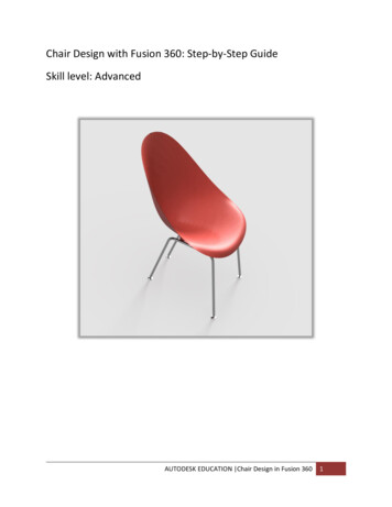
Step 2: Review the Fusion 360 User Interface1.2.3.4.5.6.7.8.Application barProfile and HelpToolbarViewCubeBrowserCanvas and marking menuTimelineNavigation bar and display settingsStep 3: Create a Box1. Click the File menu. Select New Design.2. Click Create Box.3. Select the XZ Plane along the bottom of the canvas.4. Pick two points to define the length and width of the box.Autodesk Design Academyacademy.autodesk.com8 Page
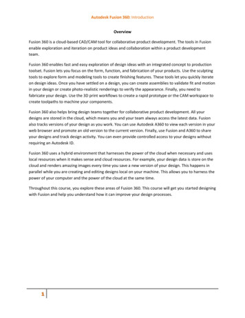
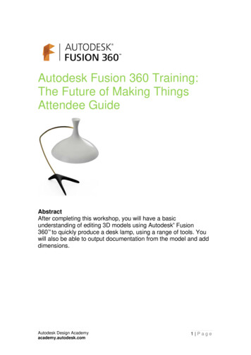
5. In the Box dialog, enter: Length: 100 mm. Width: 100 mm. Height: 50 mm.6. Click OK.Step 4: Round the Edges of the Box1. Right-click in an empty area on the canvas. Select Press Pull from themarking menu.2. Hold left-click, and then drag the window to select the entire box.3. For Radius, enter 8 mm.4. Click OK.Step 5: Add a Hole to the Box1. Click Create Hole.2. Select the top face of the box.3. Drag the center of the hole to the center of the box.4. For Diameter, enter 40 mm.Autodesk Design Academyacademy.autodesk.com9 Page
5. From the Extents list, select All.6. Click OK.Step 6: Save Your Design1. Click Save.2. In the Name field, enter My first box. Click Save. The design is saved to thecurrent project in the cloud.Step 7: Display the Data Panel1. Click Show Data Panel.2. The active project name is displayed at the top. Thumbnails of all the designsin the project are listed. All data is stored in A360 in the cloud.3. Click Hide Data Panel.Autodesk Design Academyacademy.autodesk.com10 P a g e
Step 8: Use the Browser1. Click the light bulb next to Origin. The origin planes display.2. Click the light bulb again to turn the origin plane display off.3. Click next to Bodies in the browser to expand the folder. There is one body inthis design.Step 9: Use the Timeline1. Click Play to replay the operations in the design.2. In the timeline, right-click the fillet operation. Click Edit Feature.3. For Radius, enter 5 mm. Click OK.Step 10: Change Workspaces1. Click Model. Select Render to switch to the Render workspace. The canvasappearance changes and the timeline is replaced with the Rendering Gallery.This workspace is used to render images of your design.2. Review the Rendering Gallery at the bottom of the interface. This gallerydisplays a thumbnail of your cloud renderings and shows the progress ofrenderings that are in process.Autodesk Design Academyacademy.autodesk.com11 P a g e
3. If the renderings are processed, click one of the thumbnails. The renderedimage displays.4. Close the Cloud Rendering dialog box.5. From the Change Workspace list, select Model.Step 11: Use the Navigation Bar1. Click Orbit and drag within the circle.2. Click Pan, and drag in the canvas to pan.3. Click Zoom. Drag up and down in the canvas to zoom in and zoom out.Step 12: Use the Mouse1. Roll the wheel forward and backward to zoom in and zoom out.2. Click and hold, and then drag to pan.3. Hold the Shift key, and then drag with the middle mouse button to orbit thedesign.4. Double-click the middle mouse button to zoom extents.Autodesk Design Academyacademy.autodesk.com12 P a g e
Step 13: Use the ViewCube1.2.3.4.Left-click and drag the ViewCube to orbit the design.Click one of the corners of the ViewCube to go to an isometric view.Click the FRONT face to go to the front orthographic view.Click Home to return to the Home view.Autodesk Design Academyacademy.autodesk.com13 P a g e
Hot KeysCommandUndoRedoCopyPasteCutSculpt Workspace SelectionGrow selectionShrink selectionLoop selectionLoop grow selectionRing selectionRing grow selectionRing shrink selectionPrevious UWindowsCtrl ZCtrl YCtrl CCtrl VCtrl XWindowsShift Up arrowShift Down arrowAlt PAlt OAlt LAlt KAlt JAlt Left arrowMacCommand ZCommand YCommand CCommand VCommand XMacShift Up arrowShift Down arrowControl PControl OControl LControl KControl JControl Command Left arrowNext UAlt Right arrowControl Command Right arrowPrevious VAlt Down arrowControl Command Down arrowNext VRange selectionInvert selectionToggle box modeToggle control frame modeToggle smooth modeSelect edge ringSelect face ringAlt Up arrowAlt MAlt NCtrl 1Ctrl 2Ctrl 3Double-click an edgeSelect two faces, thendouble-click a third face.Control Command Up arrowCommand MCommand NCtrl 1Ctrl 2Ctrl 3Double-click an edgeSelect two faces, thendouble-click a third face.Edit Form CommandWindowsAdd geometry.Alt DragAdd geometry and keep creases. Alt Ctrl DragAutodesk Design Academyacademy.autodesk.comMacOption DragOption Command Drag14 P a g e
Lesson 2: SketchIn this lesson, you: Start Fusion 360. Attach a canvas. Create a sketch profile of the lampshade.Note: The Lampshade Design project and data sets are required for this lesson. Ifyou have not created the project or uploaded the files, refer to the Getting Startedsection.Step 1: Start Fusion 3601. Start Fusion 360.2. If required, sign in using your Autodesk ID.3. Click Show Data Panel.4. Review the project name. It should be Lampshade Design. If it is, thenproceed to Step 2: Attach a Canvas. If not, complete the following steps.5. In the list of projects, double-click Lampshade Design to make it active.Autodesk Design Academyacademy.autodesk.com15 P a g e
6. Click Hide Data Panel.Step 2: Attach a Canvas1. Click File New Design.2. Click Insert Attached Canvas.3. Select the lower plane as shown.4. In the Attached Canvas dialog box, click Select Image.5. Navigate to the data sets folder, and then select ShadeProfile. Click Open.The image is placed on the selected plane.6. Zoom into the image. If required, rotate the image to the position as shown.7. Click OK.8. On the ViewCube, click Top.9. In the browser, expand the Canvases folder.Autodesk Design Academyacademy.autodesk.com16 P a g e
10. Right-click ShadedProfile. Click Calibrate.11. Click the origin of the sketch (1) and the right-hand point (2) as shown.Click 2Click 112. Enter 135. Press Enter.13. Zoom out to view the calibrated sketch.14. In the Browser, right-click ShadeProfile. Click Edit Canvas.15. In the Edit Canvas dialog box, for Canvas Opacity, enter 50.16. Drag the sketch to align the origins as shown.Drag thismanipulatorAlign thesepoints17. Click OK.Autodesk Design Academyacademy.autodesk.com17 P a g e
Step 3: Create a Sketch Profile of the Lampshade1. Click Sketch Create Sketch.2. Select the plane as shown.3. Click Sketch Line.4. Click the sketch origin (1), and then drag the cursor to right-hand point (2).5. Enter 135. Press Enter.Click 1Drag to here6. Right-click in the graphics window background. Click Repeat Line.Autodesk Design Academyacademy.autodesk.com18 P a g e
7. Enter 192. Press Enter.8. Repeat this workflow, and draw a short line, 24 mm long, as shown.9. Click Sketch Spline.10. To start the spline, click the bottom-right point, and then click along the sketchevery 15 to 20 mm.Click to startAutodesk Design Academyacademy.autodesk.com19 P a g e
11. Continue clicking points to complete the spline. Right-click and click OK.12. In the browser, click the light bulb next to the ShadeProfile canvas to turn offthe visibility of the sketch.13. Review the spline. If required, click points to smooth out the spline.14. Click Stop Sketch.Autodesk Design Academyacademy.autodesk.com20 P a g e
Lesson 3: ModelIn this lesson, you model the lampshade using the Revolve tool. For videoinstructional support, download the step-by-step video tutorials for this activity.Step 1: Create a Solid Model1. Click the top-right corner of the ViewCube to rotate the sketch.2. Click Create Revolve.3. Select inside the sketch.4. In the Revolve dialog box, click Axis Select.5. Select the vertical line on the sketch.Autodesk Design Academyacademy.autodesk.com21 P a g e
6. Click OK.Step 2: Modify the Solid Using Shell1. Click Modify Shell.2. Select the top face of the model to remove it from the shell operation.3. Rotate the model to view the bottom face, and then select the bottom face.4. In the Shell dialog box, for Thickness, enter 1.5 mm.5. Click OK.Autodesk Design Academyacademy.autodesk.com22 P a g e
6. Rotate the model to view it as shown.7. On the ViewCube, click the top corner as shown. The view names on yourViewCube may be different.8. Right-click the ViewCube. Click Set Current View as Home Fit to View. Thisdefines a new Home view.Step 3: Modify the Physical Material1. Click Modify Physical Material.2. In the Physical Material dialog box, expand the Metal folder.Autodesk Design Academyacademy.autodesk.com23 P a g e
3. Drag Aluminum onto the lampshade model. The material and color of themodel are modified.4. In the Physical Material dialog box, click Close.Step 4: Modify the Appearance1. Right-click the model. Click Appearance.2. In the Appearance dialog box, expand the Paint Glossy folder.3. Scroll down the list to Paint – Enamel Glossy (White).Autodesk Design Academyacademy.autodesk.com24 P a g e
4. Drag Paint – Enamel Glossy (White) onto the lampshade model. The materialcolor is modified. Note that the physical material is still aluminum.5. In the Appearance dialog box, click Close.6. On the Application bar, click Save.7. For Name, enter My Lampshade Design.8. Click Save. Your design is saved in the Lampshade Design project in thecloud.Autodesk Design Academyacademy.autodesk.com25 P a g e
Lesson 4: Model the ArmIn this lesson, you create the arm for the desktop lamp using the Sweep command.This requires the creation of a profile and a path.Step 1: Create a Hole in the Lampshade1. Click Sketch Create Sketch.2. Select the plane as shown.Select thisplane3. On the ViewCube, click the face as shown.4. Click Sketch Circle Center Circle Diameter.5. For the circle center, select the point as shown.Select thispoint6. Drag the circle preview out and enter 8 mm. Press Enter.Autodesk Design Academyacademy.autodesk.com26 P a g e
7. Click Stop Sketch.8. On the ViewCube, click Home.9. Click Create Revolve.10. Select the circle, ensuring that the complete circle is selected.11. Drag the arrow to the left. Note that on the Extrude dialog box, Cut isdisplayed as the Operation.12. For Distance, enter 20 mm. Click OK. The hole is created in the lampshade.Autodesk Design Academyacademy.autodesk.com27 P a g e
Step 2: Create a Hole in the Lampshade1. On the navigation toolbar, click Display Settings Visual Style Shaded withHidden Edges.2. On the ViewCube, click the front face as shown.3. Click Sketch Create Sketch.4. Select the plane as shown.Select thisplane5. Click Sketch Line.Autodesk Design Academyacademy.autodesk.com28 P a g e
6. Draw a 25 mm line from the center of the lampshade through the center ofthe hole as shown.7. Zoom out to provide space for the sketch of the path.8. Click Sketch Arc 3 Point Arc, and then click the left end of the 25 mm line.Click 19. Drag the cursor to the left so it is level with underside of the lampshade asshown. Click to place the endpoint of the arc as shown.Click 2Autodesk Design Academyacademy.autodesk.com29 P a g e
10. Drag the cursor up to create a shallow arc. Click to place the third point andcreate the arc.Click 311. Repeat the previous workflow to create a second arc as shown.12. Right-click, then click OK.13. Click Sketch Fillet.14. Select the 25 mm line and the arc as shown.15. For the arc radius, enter 40. Press Enter.16. Right-click in the graphics window to display the marking menu. Click RepeatFillet.Autodesk Design Academyacademy.autodesk.com30 P a g e
17. Add a 40 mm fillet between the 2 arcs as shown.18. Click Stop Sketch.19. If required, drag the center points and endpoints of the arcs to refine theshape of the sketch path. Your sketch should be approximately the same asshown.Step 3: Create a Hole in the Lampshade1. In the browser, expand the Bodies folder. Click the light bulb icon to hide thelampshade.2. Click Construct Plane Along a Path.Autodesk Design Academyacademy.autodesk.com31 P a g e
3. Select a point on the 25 mm line, close to the right end as shown.Point on line4. In the Plane Along a Path dialog box, for Distance, enter 0. Click OK.5. On the ViewCube, click Home.6. Click Sketch Create Sketch. Select the plane.7. Click Sketch Circle Center Circle Diameter.8. For the circle center, select the point as shown.Center point9. Drag the circle preview out. Enter 7.5 mm. Press Enter.10. Right-click in the graphics window. Click Repeat Center Diameter Circle.11. Create a 5.5 mm diameter circle on the same center point as shown.Autodesk Design Academyacademy.autodesk.com32 P a g e
12. Click Stop Sketch.13. Click Create Sweep.14. For Profile, select the area in between the two circles as shown.15. In the Sweep dialog box, click Path Select. Select the arc.16. Click OK.17. Zoom out to view the arm.Step 4: Modify the Physical Material and Appearance1. Click Modify Physical Material.2. Expand the Metal folder. Drag Brass from the list onto the arm.3. On the Physical Material dialog box, click Close.4. In the browser, turn on the visibility of the lampshade body.Autodesk Design Academyacademy.autodesk.com33 P a g e
5. On the navigation toolbar, click Display Settings Visual Style Shaded.Autodesk Design Academyacademy.autodesk.com34 P a g e
Lesson 5: SculptModel the desktop lamp stand using the free-form sculpt environment.Step 1: Model the Stand1. Click File New Design.2. Click Create Form.3. On the Sculpt Environment dialog box, click OK.4. Click Create Box.5. Select the plane as shown.6. Enter 25 for the first dimension.7. Press Tab. Enter 30 for the second dimension. Click to place the rectangle.8. For height, enter 25. Click OK.9. Click Symmetry Mirror – Internal.Autodesk Design Academyacademy.autodesk.com35 P a g e
10. Select the two faces as shown. Click OK.11. Select the two faces as shown, holding down the Shift key to make multipleselections. Note that the two faces on the other side of the symmetry line arealso selected.Face 1Face 212. Click Modify Edit Form.13. Hold down the ALT key and drag the manipulator as shown.Drag thismanipulatorAutodesk Design Academyacademy.autodesk.com36 P a g e
14. For distance, enter 125.15. Drag the manipulator as shown. Enter 75.Drag thismanipulator16. Drag the manipulator as shown. Enter -50 (negative value).Drag thismanipulatorStep 2: Edit the Form1. On the ViewCube, click Home.Autodesk Design Academyacademy.autodesk.com37 P a g e
2. Double-click the edge as shown.Double-clickthis edge3. Double-click the other edge as shown. The edge around the model is nowselected.Double-clickthis edge4. Right-click in the graphics background. Click Edit Form.5. Drag the manipulator approximately 5 mm as shown.Drag thismanipulatorAutodesk Design Academyacademy.autodesk.com38 P a g e
6. Drag the manipulator approximately -5 mm (negative value) as shown.Drag thismanipulator7. Repeat these two edits to make minor changes to the model. Make sure theedits are small.8. Click OK.9. On the ViewCube, click the corner as shown.Autodesk Design Academyacademy.autodesk.com39 P a g e
10. Select the two faces as shown.11. Right-click in the graphics background. Click Edit Form.12. Drag the manipulator as shown. Enter -50 (negative value).13. Drag the manipulator as shown. Enter -50 (negative value).Autodesk Design Academyacademy.autodesk.com40 P a g e
14. Rotate the model as shown.15. Drag the scale manipulator as shown. The scale reduction is approximately0.5.Drag thismanipulator16. Click OK.17. On the ViewCube, click Home. Review the design.Autodesk Design Academyacademy.autodesk.com41 P a g e
18. On the ViewCube, click the front face as shown.19. Double-click the model.20. Right-click in the graphics background. Click Edit Form.21. Drag the manipulator to align the model with the plane as shown.22. Click OK.23. Select the two faces as shown.24. Right-click in the graphics background. Click Edit Form.Autodesk Design Academyacademy.autodesk.com42 P a g e
25. Drag the manipulator to align the model with the plane as shown.Align withthis plane26. Click OK.27. Repeat this workflow to align the left side of the model. Click OK.28. On the ViewCube, click Home.29. Click Symmetry Clear Symmetry.30. Select the model. Click OK.31. Click Finish Form.Step 3: Add a Hole1. Click Construct Plane at Angle.2. Select the axis as shown.Select thisaxis3. On the ViewCube, click the front face to view the model as shown.Autodesk Design Academyacademy.autodesk.com43 P a g e
4. Rotate the plane counterclockwise 30 degrees.5. Click OK.6. Click Construct Offset Plane.7. Select the angled plane, and then drag the offset plane above the model asshown.8. Click OK.9. Rotate the model as shown.10. Click Sketch Create Sketch. Select the offset plane.11. Zoom into the top of the model.12. Click Sketch Point.Autodesk Design Academyacademy.autodesk.com44 P a g e
13. Click to place a point as shown.Createpoint here14. Click Sketch Circle Center Diameter Circle.15. Select the point as the center of the circle. Enter 8 mm for the diameter.16. Press Enter to create the circle.17. Click Stop Sketch.18. On the ViewCube, click Home.19. Click Create Extrude.Autodesk Design Academyacademy.autodesk.com45 P a g e
20. Select the circle, and then drag the manipulator through the model as shown.21. In the Extrude dialog box, for Extents, select All from the list.22. Click OK. The hole is created in the model.Step 4: Modify the Physical Material and Appearance1. Click Modify Physical Material.2. From the Metal folder, drag Aluminum onto the model.3. Click Close.4. Right-click in the graphics window. Click Appearance.5. From the Paint Powder Coat Rough folder, drag Powder Coat – Rough –(Black) onto the model.Autodesk Design Academyacademy.autodesk.com46 P a g e
6. Click Close.7. In the browser, expand the Construction folder. Turn off the visibility of theangled plane.8. Save the file.Autodesk Design Academyacademy.autodesk.com47 P a g e
Lesson 6: AssembleAssemble the desktop lamp using joints.Step 1: Modify the Arm1. The lampshade design should be open.2. In the browser, expand the Bodies folder. Right-click the first entry. SelectCreate Components from Bodies.3. Select the new component. Rename it Lampshade.Autodesk Design Academyacademy.autodesk.com48 P a g e
4. Repeat this workflow for the second body. Rename it Arm.5. Expand the Sketches folder. Make the path sketch from the arm visible. Toidentify which sketch is correct, move the cursor over each sketch. You willsee them highlighted in the model.6. In the browser, right-click the sketch. Click Edit Sketch.7. On the ViewCube, click the front face of the cube. Zoom into the lower end ofthe sketch.8. Click Sketch Line.9. Draw a line 10 mm long and at a 30-degree angle.10. Press Enter to complete the line.11. Click Sketch Fillet. Create a 40 mm arc between the two lines.Autodesk Design Academyacademy.autodesk.com49 P a g e
12. Click Stop Sketch.13. Right-click the arm. Click Edit Feature.14. In the Edit Feature dialog box, click Path 1 selected. Select the extendedline.15. Click OK. The arm feature is updated.16. On the ViewCube, click Home.17. In the browser, turn off the visibility of the path sketch.Step 2: Assemble the Lampshade and the Arm1. The lampshade design should be open.Autodesk Design Academyacademy.autodesk.com50 P a g e
2. In the browser, right-click the lampshade. Click Ground. The lampshadecannot move.3. Click Assemble As - Built Joint.4. Select the lampshade and then the arm.5. In the As-Built Joint dialog box, the Rigid joint should be selected.6. Click OK.7. In the browser, expand the Joints folder. The rigid joint is displayed. Your jointnumber may be different.8. Click Show Data Panel.9. Right-click the stand design. Click Insert into Current Design.Autodesk Design Academyacademy.autodesk.com51 P a g e
10. Use the manipulators to rotate and drag the model closer to the end of thearm.11. Click OK.12. Zoom into the end of the arm and the hole in the stand.13. Click Assemble Joint.14. Select the circular edge of the arm.Autodesk Design Academyacademy.autodesk.com52 P a g e
15. Rotate the model to view the edge of the hole in the stand. Select the centerof the circle as shown.16. In the Joint dialog box, for Offset, enter 5 mm.17. Click OK. The stand is assembled to the arm using a rigid joint.18. On the ViewCube, click Home.19. Save the file.Autodesk Design Academyacademy.autodesk.com53 P a g e
Lesson 7: DocumentDocument the lampshade design by creating a drawing with orthographic views.Step 1: Assemble the Lampshade and the Arm1. The lampshade assembly design should be open.2. Save the file.3. View the lamp as shown.4. Right-click the ViewCube. Select Set Current View As Front.5. Click File New Drawing From Design. Click OK.Autode
Download Fusion 360 Fusion 360 is the first 3D CAD, CAM, and CAE tool of its kind. It connects the entire product development process in a single cloud-based platform that works on both Mac and PC, and has many features accessible from a web browser. You can find more information about Fusion 360 and its features here: