Transcription
Colour ID Card PrinterMAGICARD Rio/TangoUser Reference ManualIssue 1.00 June 1st 2002
DYE-FILM TYPES4CARD DETAILSCARD SIZE:CARD THICKNESS:TO OBTAIN GOOD QUALITY PRINTS THE CARD MUST BE:PRINTABLE AREA OF THE CARD:44444SELF - ADHESIVE CARDS4CONTACT & CONTACTLESS CHIP CARDS5UPGRADING YOUR PRINTER FIRMWARE5CLEANING AND TESTING5 , HOLOPATCH AND ULTRASECURE SECURITY LOGOSHOLOKOTE6LOADING THE PRINTER DRIVER7ACCESSING THE DRIVER SETTINGS7 LAYOUT OF THE WINDOWS 95 / 98 / ME DRIVERTAB SELECTIONS:General tabDetails tabColour Management tabSharing tabPrinter tab8888999Advanced buttonPrinthead Position:Image Position:Start Position:End Position:Data Download Format:Printer controls buttonMagnetic Encoder Settings button1010101010101010Ribbon tab10Colour Format OptionsOvercoat HoloPatchResin Black Button OptionsOvercoat Button Options:Overcoat Security Selections:Overcoat Area Selections:Overcoat Holes Selections:10101111111111Card Tab:12Image SizeCard OrientationFlip Front / Back 180o121212Colours Tab:12Gamma CurveRGB Adjustment buttonPrinthead Power AdjustmentsPerform Colour MatchingAdvanced button1212121212 NT, 2000 & XP DRIVERLAYOUT OF THE WINDOWS213
DRIVER GUIDE FOR MAGNETIC ENCODINGENCODER SETTINGS WINDOWSelect Enable macro processing.ADVANCED SETTINGSEncoding CoercivityMagnetic Stripe Positional AdjustMagnetic VerificationTrack Settings1515151616161616ModeDensityStart and Stop CharactersCharacter Parity and LRC parity16161616 THE MAGICARD SUPPORT TOOLSTHE SUPPORT TOOLS WINDOWThe Communications tab171717Refresh Data button17The Configuration tab18Adjusting the Image Start PositionAdjusting the Image End PositionAdjusting the Print Density181818The Statistics tabThe Information tabThe Firmware tab191919To Update the Firmware:19APPENDIX AMAG COMMAND STRUCTURE REQUIRED FOR ISO STANDARD ENCODING32020
Dye-film TypesLC/1. (YMCKO) five panel film - Yellow, Magenta, Cyan, Resin Black and clear Overcoat. Fullcolour, 350 images per roll. Generally used to print colour images and black text / barcodes.LC/3. (K) Monochrome Resin Black, no Overcoat, 1000 images per roll.Prints monochrome images without overcoat.Available in Black, Gold, Silver, Blue, Red, Green, White and YellowLC/6. (KO) Monochrome Resin Black with protective Overcoat, 600 images per roll.LC/8. (YMCKOK) six panel film - Yellow, Magenta, Cyan, Resin Black, Clear overcoat and ResinBlack to print on rear side of card. 300 images per roll. Tango model only.Card DetailsCard Size:Must be:86.5 mm wide x 53.98mm high (3.375” x 2.125”)Card Thickness:MinimumStandardMaximum-0.38mm (0.015”)0.76mm (0.030”)1.60mm (0.063”)To obtain good quality prints the card must be:Free from dirt and grease.Free from surface contamination.Free from pits and bumps in the surface.Free from burrs at the edge of the card.Completely flat.Printable Area of the Card:Both the Rio and Tango printer offer high quality edge to edge (full bleed) printing. Thus the wholeupper surface of the card may be utilised by the customer.Maximum Page Size - 1026 pixels (86.9mm) x 624 pixels (54mm)For full bleed printing guillotined cards are recommended, as pressed or stamped PVC cards haveedge roll off which can cause a white line around the edge of the card.Self - Adhesive cardsThere are many different types and manufacturers of self-adhesive cards. Thorough investigationand testing has shown that the use of poorer quality or incorrect type of cards will cause problemsin the printer. These problems range from poor image quality, through failure to feed from the cardhopper, to getting jammed in the roller mechanism.For this reason, we recommend only the use of cards supplied by Ultra Electronics via yourMagicard dealership.In addition, we also recommend the use of a Self-Adhesive Card Weight, placed in the hopper ontop of the cards, to aid reliable feeding of the cards. These can be obtained from Ultra Electronicson 44 (0) 1305 784738.4
Contact & Contactless Chip cardsSmart cards must conform to the ISO 7816 specification with the chip contacts being below thesurface of the card. It is unwise to print graphics or text directly adjacent to the chip as colourvariation may be noticed.Proximity cards must be completely flat with no sign of the chip or antenna being visible in thesurface of the card.If the printer is built with the necessary contacts for encoding, it is possible to encode smart cardsprior to printing the image on them so it becomes a continuous operation.The printers’ firmware has commands available to enable software to position the card, allowencoding from an external source and subsequent printing of the related image.For Contact chip cards a set of pins connects the card chip contacts to a connector on the rear ofthe printer. This enables the transfer of data from the computer or encoding hardware.For Contactless Mifare cards a communication unit in the printer connects to a connector on therear of the printer. This enables the transfer of data to and from the computer or encodinghardware.Upgrading your Printer FirmwareThe Rio and Tango printers are designed so that future improvements can be downloaded from ourwebsite http://www.ultramagicard.com/support/downloads to keep your printer up to date with allour latest research.This is achieved by downloading the file from the website and using the Magicard Support Tools(MST) to install it into the printer. The use of the MST is explained in a later section of these notes.(See page 17).Cleaning and TestingThe printer has an automatic test and cleaning system. This is operated from a small blackbutton situated on the rear of the printer above the USB connector. The cleaning will ensurecorrect card movement and the testing allows the printer to be checked without input fromthe computer or software.To clean the printer :(Also watch the explanatory Video on the printer driver CD supplied with the printer) Remove the card hopper and open the top door (Red light comes on). Take a fresh cleaning card from its foil packaging. Insert the narrow end into the card feed slot. Press the black button and the card is drawn into the printer and then ejected. Repeat this several times with both sides of the same card.To test the printer : Ensure there are cards in the hopper, and the top door is closed (Green light is on). Press and immediately release the black button After a few seconds the light will start to flash. After about 15 seconds a card will print with a test image on it.5
HoloKote , Holopatch and UltraSecure Security LogosThe counterfeiting or creation of fake ID cards has never been easier, but now, thanks toMagicard’s HoloKote key controlled anti-counterfeiting card protection feature, an affordablesolution is available.Protection from forgery is achieved thanks to Ultra’s patented HoloKote system which cannoteasily be copied or bypassed.This unique security feature incorporates a repeating frosted security logo into the overcoat laiddown during the normal print cycle. When the card is viewed normally, the feature is invisible,revealing only the underlying text and portrait. When flexed or held at an angle to direct light, thefeature is clearly visible on the face of the card.When used with the optional Ultra HoloPatch card stock, one of the security logos is highlightedby a highly reflective gold ‘super-diffuser’ patch, making the logo clearly visible under all lightingconditions and for easy recognition at a distance. HoloKote with HoloPatch has a similarappearance to credit card hologram patches.A standard HoloKote logo (a key symbol) is built in to the Magicard Rio and Tango card printers,but increased security can be achieved through the use of an encrypted custom logo which iselectronically stored in a miniature ‘Compact Flash’ sized UltraSecure key.HoloKote costs absolutely nothing to use, and the custom logo set-up charges for UltraSecure keys are minimalWarning: The printer must be switched OFF before fitting or removal of the UltraSecure key.6
Loading the Printer DriverThe driver can be loaded on the computer using the CD supplied with the printer, or bydownloading the files from our company Website: http://www.ultramagicard.com/support /downloads CD autoboot CD, choose install printer drivers and follow the prompts. Downloaded File Unzip , run the set-up program from My Computer / Explore andfollow the prompts. Upgrading the Driver do not delete the old driver, install as above choosing Replaceexisting Driver, the old driver will be deleted, the computer re-boots and the new driverwill install. ( If it does not then run the install as above).Accessing the Driver SettingsThe driver menu can be entered via 2 routes :1)2)Enter via the Windows Start button in the bottom left hand corner of thescreen.Select ‘Settings’ – ‘Printers’Right mouse click on the specific printer. If using Windows 95/98, select ‘Properties’. The Properties Menu will appear. Alladjustments and settings are available when entering the Properties Menu this way. If using Windows NT, the print quality parts of the driver are accessed via ‘DocumentDefaults’ selection in the pull down menu. If using Windows 2000, the print quality parts of the driver are accessed via ‘PrintingPreferences’ but can also be found through the ‘Properties’ selection in the pull downmenu.Select ‘Print’ from either the ‘File’ menu or the ‘Print’ icon on the tool bar fromwithin your software (whichever is available). Select ‘Properties’. The Properties Menu willappear. Some of the printer settings are not accessible when entering the menu this way.(Use method 1above)The Magicard printer driver differs in appearance depending on the version of Windows being used. The commands are the same, only the visual layout is different.7
Layout of the Windows 95 / 98 / ME DriverThis chapter explains how the various tools within the Print Properties Menu allow the user to makeadjustments to achieve optimum print results.To enter the properties menu:On your computer select; Start Settings Printers.Right click your mouse on the relevant printer.Select Properties.The Properties Menu will appear with 8 tabs on the screen. All adjustments andsettings are available when entering the properties menu this way. The use of eachindividual tab and tool contained therein will now be explained.Tab Selections:General tab This page gives the name of the printer in use. There is a comment box available for any notes about theprinter. Separator Page. Prints a blank page between print runs. Canbe useful if printing a number of multiple documents. The Browse selection allows you to specify a custom separatorpage. Print Test Page. This prints a test page containing the logo.On completion of the test print it asks if the card printedcorrectly, with the option of Yes / No.Yes - Returns to the General MenuNo - Will display the Windows Trouble Shooting GuideDetails tab Gives details and options of both printer Ports and Drivers. The port option allows you to sendyour print to file; this can be a very useful fault diagnosis tool. Allows time out and retry periodicity to be adjusted. Allows spool settings to be adjusted. This can affect the time to download and hence to print.Spooling is the process of first storing the document to the hard disc and then sending theinformation to the printer. It is usual to operate with the following selections.Select Spool Print DocumentsStart Printing ImmediatelyPrint Spooled Documents First8
Colour Management tab (not available in Windows 95) The colour profile controls the colour on your printer based on the type of monitor being used.Different monitors show different colours for the same RGB setting. Colour managementattempts to correct these differences so that the colour being printed is the same as the colourbeing displayed on the monitor.This selection is set to automatic by default.Other colour profiles can be added using the ADD button, this allows entry to the Profileassociation files. Select as required, this can also be selected as the default.Sharing tab Not available in Win 95. This allows the printer to be available to Network users.Printer tabPrinter Model:Selects the type of printer being used, Rio, Tango, Standard, Magnetic Encoding etc.Printer Options:Selections available within this field vary with the type of printer model selected. Print on both sides. (Tango models only). Backside only – prints on the back of the cards only. (Tango models only). Hand Feed Cards – when selected cards are hand fed through the front of the printer. Chip Proximity Cards Allows use of this type of card if printer is capable of encoding them. Encode Only – printer encodes magnetic stripe information and then ejects the card. It ignoresany image data. (Magnetic Encoding variants only). ColorSure Mode – Adjusts the print speed to allow the printer to print more difficult colours.9
Advanced buttonGives access to the ‘Advanced Printer Options’ Printhead Position: Image Position: Start Position: End Position: Data Download Format:By using the sliding control the image position can be moved verticallyon the card (when viewed in landscape). This allows the image to befully centralised on the card. After selection the OK button must beselected or the printhead position will return to the default setting.By using these sliding controls, the image position on the card can bemoved in the horizontal plane from the datum settings set in theMagicard Support Tools.Moves the image left (L) and right (R) at the front edge of the card(when viewed in landscape).Moves the image left (L) and right (R) at the front edge of the card(when viewed in landscape).This selection allows the user to choose from a variety of methods todownload data from the computer to the printer and thereby optimiseprint speed. If using the LPT port the fastest prints are obtained using the ‘Compress data' option. Thecompression ratio can be selected using the ‘Data width’ adjustment. Data width 4 maximum compression, data width 7 minimum compression. Please note that reducingthe data width may reduce the image quality. If using the USB port the fastest prints are obtained using the ‘Fast Layer by Layer mode’.Printer controls buttonGives access to the printer controls pageMagnetic Encoder Settings buttonGives access to the ‘Encoder settings’ page. Please refer to Driver Guide andAppendix A for magnetic encoding information.Ribbon tabColour Format OptionsYou can select the colour format you want to usefor each side of the card from the following options:YMC Colour and Composite BlackYMCK Colour and Resin BlackKD Diffusion BlackKR Resin BlackOvercoat HoloPatchEnable: for printing secure logo on pre-preparedcards with metallic square patch.Position: to select where the logo is placed tocoincide with metallic patch.10
Resin Black Button OptionsThe various options available decide how the black colour istransferred to the card, either as a composite of the 3 colour panels,directly from the resin black panel or a combination of resin black laidover the composite black.The following selections are available:Do Not Use:Prints only in Composite BlackUse Always:Prints all black in Resin BlackText Only:Prints text in Resin BlackExcept in Colour Picture: Prints Resin Black except in the photographThis control should be experimented with as both the definition andintensity of the black can be varied to suit a number of image types.This is particularly important if printing barcodes or photographs containing a large amount of blackwhen it is recommended that either text only or except in colour picture are used.The Advanced selection compares the black pixels in the image with those around it andcompensate accordingly to produce optimum results.Overcoat Button Options:Overcoat Security Selections:The protective overcoat can be laid in one of thefollowing forms:No Secure Overcoat: Prints the card with a clearprotective coating.Ultra Secure:Prints the Ultra Secure key and textover the surface of the card.Ultra Shield:Prints the Ultra Security Key without theovercoat, used when cards are to belaminated.Tile Rotate:Rotates the overcoat to print the correctway up in either shield, secure orHolokote key.Overcoat Area Selections:Overcoat Enabled:User Defined:Enables the cards to be printed with or without the protective overcoatapplied.This selection allows you to define the areas of the card upon you wish theprotective overcoat to be applied.Overcoat Holes Selections:Used when printing chip cards or double-sided cards, It allows the overcoat to be laid while leavinga hole around the chip or along the magnetic stripe as defined by the user. The user-definedsettings start at the top left of the card as 0 top and 0 left and go out to 1026 right, 641 bottom.11
Card Tab:Image SizeAllows the customer to choose between Full bleededge to edge setting, with the whole surface of thecard printed, or printed with a white border around theedge of the card.Card OrientationEither landscape or portrait.oFlip Front / Back 180Changes the orientation of the print as it is transferredto the card.Colours Tab:Gamma CurveSet to ‘Default’ to give a boost to mid-tone colours, good for photos etc, or to ‘None’ for a linear colouroutput.RGB Adjustment buttonAllows you to adjust the image colour contrast andintensity levels, these changes apply to the wholecard and not just the pictures.IntensityIncrease or decrease the image intensity by movingthe RGB sliders left or right. This will change theoverall lightness or darkness of the individual colouron the image.ContrastMagnifies or minimises the difference between thelight and dark parts of the image for each individualcolour.A Restore Defaults button allows you to reset thedriver default settings.NOTE:PRINTED COLOURS CAN APPEAR DIFFERENT TO DISPLAY COLOURS.CONTROLS SHOULD ALLOW YOU TO OPTIMIZE THE PRINTED RESULT.THE ABOVEPrinthead Power AdjustmentsThis control allows the customer to adjust the energy applied to the nominated panel of the dye filmduring the printing process. It allows adjustments to compensate for image quality issues related tothe use of differing card stocks.Perform Colour MatchingWhen selected this automatically attempts to match the monitor and theprint colours.Advanced buttonAllows you to alter the mathematical composition of the monitor colourmatching parameters if you know them.12
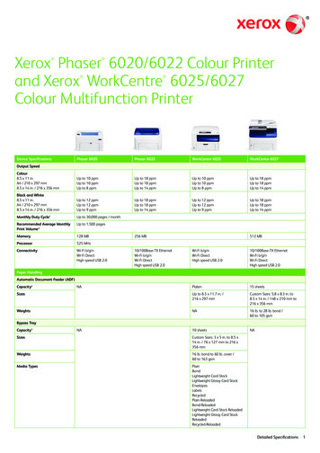
Layout of the Windows NT, 2000 & XP DriverThe style of the driver layout for Windows NT, 2000 & XP is shown below. The commands andselections are the same as for the Windows 95, 98 & ME driver described above, only the visuallayout is different.Windows NT, 2000 & XP Propertieswindow and showing Printing Preferencesaccess button (not available in NT).Ports window showing Printer Portsavailable From here the driver can beselected for USB (not available in NT), LPT1,2,3,4 or File (output to disk).The ‘Device Settings’ window allowsaccess to the same settings described inthe next chapter.The Advanced Options has the samechoices as the Windows 95/98 Driversection but the layout of the window isdifferent (as shown).13
The full selection tree for Windows NT, 2000 & XP giving access to all print control options. (Ason the Magicard Card Printer Advanced Document Settings screen print above)Magicard Card Printer Advanced Document Settings. Paper Output Paper Size Copy Count Document Options Flip Printing Options Front Colour Format Resin Black Overcoat Back Colour Format Resin Black Overcoat HoloPatch Orientation (Portrait / Landscape) Front Back 180 Rotation Colour Gamma Correction Colour Matching RGB Adjustment Printhead Power YMC Black Resin Overcoat Encode Only Print QualityA full explanation of the functions of these selections is given above in the Windows 95/98 Driver section.14
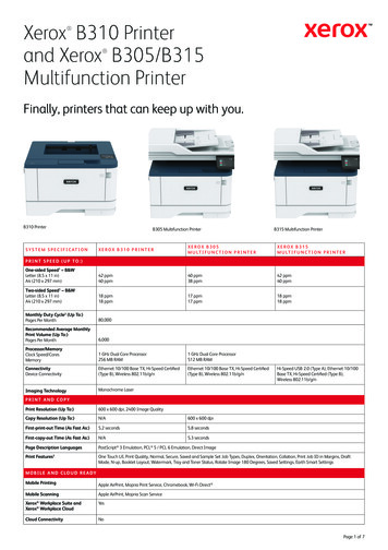
Driver Guide for Magnetic EncodingWindows NT, 2000 & XPWindows 2000: Within the PrinterProperties page go to the DeviceSettings tab, select MagneticEncoder Settings and click on theProperties button.Note:Windows 95, 98 & MEWindows 95/98: Within the PrinterProperties page go to the Printer tab andclick on the Magnetic Encoder Settingsbutton to configure the magnetic encodersettings for your printer.All Encoder Settings and Advanced Settings are initially defaulted to the ISOstandard.Encoder Settings WindowSelect Enable macro processing.This enables the driver to convert informationsent by the application into magnetic encodingdata recognisable by your printer.The Macro start and Macro end functionsenable you to specify the characters thatdenote the beginning and the end of amagnetic encoding data string.If you wish the driver to use the tilde method(most commonly used) i.e. track 1 data will bespecified by: 1, data do not change any of the settings on this page. Note: the tilde method does not have a Macro endcharacter.If however you want track 1 data to be expressed by:#1, data @choose ‘#’ as the Macro start character and ‘@’ as the Macro end character, modify the macro asshown.15
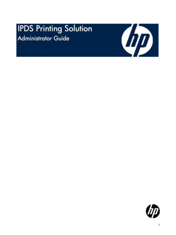
Advanced SettingsWithin this page you can manually select theEncoding Coercivity and Track Settings, oralternatively you can select User Specify in whichcase the driver will take the settings from thebadging application. These settings will either beset in the application software or they can bespecified on the image.Encoding CoercivityDepending on the type of cards being used, select either ‘High coercivity’, ‘Low coercivity’ or if set inthe badging application, ‘User Specify’.Magnetic Stripe Positional AdjustUsing the slider you can change the position along the magnetic stripe at which the printer willbegin encoding.Magnetic VerificationSelect this option if you wish the printer to verify that thecard has been correctly encoded before printing.Track SettingsToggle between tracks using these buttons.ModeUse this function to select 7, 6, 5, 4 or 1 bit magneticencoding data for the track selected. Alternativelychoose user specify box if you wish these to bespecified by the badging application.DensityUse this function to select a bit density of 75 or 210 bitsper inch (BPI) for the track selected. Alternativelychoose User Specify.Start and Stop CharactersEnter the decimal ASCII code for the start and stopcharacters you require for each track, or tick the UserSpecify box if you wish these to be specified by thebadging application.Character Parity and LRC paritySelect odd, even or no parity for each character used in the data string, and the LRC checkdigit. Select User Specify if the parities are set in the badging application.Click on Restore Defaults if you want all the settings to revert to ISO standard.Click on Set User Specify to set all settings to user specify.Click OK to accept all the settings and exit this dialogue box.16
THE MAGICARD SUPPORT TOOLSThe Support Tools WindowThe support tools consist of 5 Windows, the function of each window is explained below.The Communications tabThis window allows you to select the port by which the Printer is connected to the computer. This isachieved by the use of a drop down button, giving you the choice of ports. It also allows you torefresh the data held on your computer by interrogating the printer settings, thereby ensuring thatthe information held on the computer corresponds with the data on the printer.To open the Support Tool Windows :1)Ensure that there is power to the printer,the printer is connected to the computerand that the printer is on-line (green lightilluminated).2)Select the Magicard Support Toolprogram on your computer.3)On the communications window dropdown panel, select the port to which theprinter is connected.4)The 5 menu tabs will now appear at thetop of the window.Refresh Data buttonUse of this button ensures that the settings onyour printer correspond to those shown onyour computer.To refresh data: 1)Ensure that there is power to the printer, the printer is connected to the computer and that theprinter is on line (Green light illuminated) .2)Select the Magicard Support Tool program on your computer. The Communications windowwill be shown by default.3)From the drop down panel on the communication window select and click on to the port towhich the printer is connected.4)Select Refresh Data (this will take approximately 5 seconds).17
The Configuration tabThis page provides you with information about the printer set up, - it also allows you to adjust thesesettings. The following information is shown on the screen:Image Start Position.This is the position where the image will start printing.Image End Position.This is the position where the image will finish printing.Printhead Density Calibration.This adjusts the intensity of heat at the printhead andhence controls the depth of colour achieved. However,care must be taken not to have this setting raised toohigh as this will adversely affect the Dye film.Cards printed Between Each Cleaning Prompt.This informs the customer automatically when a certainnumber of cards have been printed and cleaning isrequired. This is factory set at 350 cards, but may beadjusted by the customer.Cleaning Prompt Status.This allows the cleaning prompt to be selected to on or off.Change buttonIt is possible to alter the value of any of the above settings. Type in the new value in the window tothe right of the required setting, then press the ‘Change’ button.Defaults buttonResets all the above settings back to their original factory pre-sets.Adjusting the Image Start PositionAn increase in the number moves the image start position to the right, increasing the white leadingedge of the card. A numerical change of 8 digits moves the start position a distance of 1 line widthCautionWhen adjusting the image start position it is important that the image remains within theparameters of the card. If the image start position is moved forward of the front of the card,this will result in the cutting of the dye film.Adjusting the Image End PositionAn increase in the number moves the image end position to the right, closer to the rear of the card.A numerical change of 1 digit moves the start position a distance of 1 line width.CautionWhen adjusting the image end position it is important that the image remains within theparameters of the card. Should the image end position move off the back of the card thiswill result in the cutting of the dye film.Adjusting the Print DensityAn increase in the number increases the intensity of the colour. As a datum point the setting shouldbe reasonably close to the resistance setting shown on the printhead (example R3531) Because ofthe high numbers it is advisable to alter the settings in increments of 25 or 50.CautionWhen adjusting the print density setting it is important to note that too high a setting willcause the dye film to overheat and adhere to the cards an excessively high setting willcause the dye film to melt.18
The Statistics tabThis page will provide you with statistical informationabout the usage of your printer. This includes, thenumber of cards printed, the number of Dye panelsprinted, the number of cards printed since the lastcleaning cycle, the Dye panels printed since the lastcleaning cycle and the number of cleaning cyclescarried out.The Information tabThis page provides you with information about themajor components fitted to your printer. It shows thePrinter Serial Number, the Printer Control Board SerialNumber and the Printhead serial number. It also givesinformation about the version of Firmware fitted to yourprinter.The Firmware tabThis page allows the printer Firmware to be upgraded.The printer firmware consists of information storedpermanently in the printer - this allows it to carry out theprinting function. As improvements are made to thisfirmware a new issue is released and put onto our websitehttp://www.ultramagicard.com/.To Update the Firmware:To update the Printer Firmware, ensure that there ispower to the printer, the printer is connected to thecomputer and the printer is on line (Green lightilluminated)1)Select Browse and locate the newfirmware file that you have downloaded onto your PC.2)3)4)Click on the Upgrade Firmware button.The computer will show ‘The Firmware update has been successfully completed’.The lights on the printer will flash and then reset on line (green light) and the printer will restart.Press OK.To ensure the software has been successfully loaded, go to the ‘Communications’ tab and selectthe Refresh Data button. Now go to the ‘Information’ tab, and the printer firmware version will bedisplayed half way down the window.19
Appendix AMag Command Structure Required for ISO Standard EncodingListed below are the command instructions which must be placed in the image file controlheader for an ISO standard encoding string:CommandMAGBPIMPCCOEParameter1, 2, 375, 2107, 5H, LFunctionTrack 1, 2 or 3Bits per inchBits per characterHigh or low CoercivityCard Data FormatAll user data selected for encoding must be sent in UPPER CASE characters. The MagneticStripe data formats that can be encoded on tracks 1, 2 or 3 is as follows:Track 1 Data FormatTrack 2 Data FormatTrack 3 Data Format210 BPI, 7 BPC,75 BPI, 5 BPC,210 BPI, 5 BPC,79 alphanumeric characters40 numeric characters107 numeric charactersValid ISO Card Track Data CharactersTrack 1:Start SentinelField SeparatorEnd Sentinel% ? Start of data to be encoded. Space character. End of encoded data.Track 2:Start SentinelField SeparatorEnd Sentinel; ? Start of data to be encoded. Space character. End of encoded data.Track 3:Start SentinelField SeparatorEnd Sentinel; ? Start of data to be encoded. Space character. End of encoded data.To encode the word “MAGTEST” on Track 1 at 210 Bits Per Inch (BPI) and 7 Bits PerCharacter (MPC), on a Hi-Co card, the data added to the file header would be as f
MAGICARD Rio/Tango User Reference Manual Issue 1.00June 1 st 2002. 2 DYE-FILM TYPES 4 CARD DETAILS 4 CARD SIZE: 4 CARD THICKNESS:4 TO OBTAIN GOOD QUALITY PRINTS THE CARD MUST BE:4 . Magicard dealership. In addition, we also recommend the use of a Self-Adhesive Card Weight, placed in the hopper on