Transcription
REPORT TO THE COMMITTEE ON COMMERCE, SCIENCE, AND TRANSPORTTION OFTHE SENATE AND THE COMMITTEE ON ENERGY AND COMMERCE OF THE HOUSE OFREPRESENTATIVESSummary:This report provides a summary of the Commission’s effort to “test[] the feasibility of partnering withFederal agencies that operate delivery fleet vehicles, including the United States Postal Service (USPS orPostal Service), to facilitate the collection and submission” of mobile wireless broadband data for thepurposes of supplementing and verifying wireless broadband coverage maps collected by the Commissionpursuant to the Broadband DATA Act.1 The Commission has conducted a pilot feasibility study usingUSPS delivery vehicles in Longmont and Denver, Colorado, to explore the possible use of delivery fleetvehicles to verify and supplement mobile broadband coverage information submitted by wireless serviceproviders. After receiving Congressional funding to implement the Broadband DATA Act, Commissionstaff purchased the equipment necessary to conduct a pilot project and entered into an agreement withUSPS to conduct a study to test the feasibility of equipping USPS vehicles with 5G-capable handsets, aswell as spectrum sensing equipment, to measure mobile broadband service. This report provides asummary of the design, engineering, and mechanical work done to establish the pilot program. Thecombination of smartphones and sensor equipment successfully collected a large amount of throughputand other network performance metrics data along the delivery routes traveled by the pilot vehicles.Although the Commission was able to collect a large amount of useful data, however, the pilotdemonstrated that there are certain technical and logistical challenges and other limitations that wouldneed to be resolved in order to make it feasible for USPS fleet vehicles to be used to supplement andverify mobile broadband coverage data collected by the Commission. For example, safety, space, andpower limitations in delivery vehicles, and the imperative not to interfere with or impose burdens uponthe postal carrier, place substantial restrictions on the size and amount of equipment that can be installed.As a result, we conclude that there are a number of barriers to establishing a scalable model to operatefleet vehicles to facilitate the collection and submission of coverage maps and data speeds submitted bymobile broadband providers as part of our Broadband Data Collection efforts.Background:The March 2020 Broadband DATA Act directs the Commission to make fundamental changes to itsrequirements, processes, and approach for the collection of data on the availability and quality of fixedand mobile broadband Internet access service throughout the United States.2 As required by the Act,3 theCommission issued rules in July 2020 and January 2021 to establish a new Broadband Data Collection4for collecting granular data from providers on the availability and quality of broadband Internet accessservice, creating publicly available coverage maps, establishing processes for members of the public andother entities to challenge and verify the coverage maps, and creating a common dataset (the Fabric) of all1Broadband Deployment Accuracy and Technological Availability Act, Pub. L. No. 116-130, § 804(b)(2)(B)-(C),134 Stat. 228, 237 (2020) (codified at 47 U.S.C. § 644(b)(2)(B)-(C)) (Broadband DATA Act or Act).2Broadband Deployment Accuracy and Technological Availability Act, Pub. L. No. 116-130, 134 Stat. 228 (2020)(codified at 47 U.S.C. §§ 641-646) (Broadband DATA Act or Act).347 U.S.C. § 642.4The Broadband Data Collection was formerly known as the Digital Opportunity Data Collection.
locations where fixed broadband Internet access service can be installed.5As part of the Broadband DATA Act, Congress also directed the Commission to test the feasibility ofpartnering with federal agencies, including USPS, that operate delivery fleet vehicles to collect data thatcan be used to verify and supplement broadband coverage information.6 The goal of such partnershipswould be to “facilitate the collection and submission of information” about the actual availability ofbroadband service “on an ongoing basis so that the information may be used to verify and supplementinformation provided by providers of broadband [I]nternet access service for inclusion in the mapscreated” under the Act.7 The Broadband DATA Act further requires that the Commission submit a reportto Congress on its assessment.8On December 27, 2020, Congress authorized funding for implementation of the Broadband DATA Act.9In the January 2021 Broadband Data Collection Third Order, the Commission directed the Office ofEconomics and Analytics (OEA) and the Wireless Telecommunications Bureau (WTB) to investigate apilot program that tests the feasibility of partnering with USPS or other federal agencies to collectinformation to verify and supplement broadband information submitted by mobile providers.10Discussion:The pilot program. To begin the pilot testing as quickly as possible, and in view of the extensive USPSdelivery network, the Commission focused on establishing a partnership with USPS. USPS is anindependent establishment of the executive branch of the United States government and maintains a fleetof more than 230,000 delivery vehicles.11 USPS delivers mail across the United States, providing serviceto over 160 million delivery points across a range of urban, suburban, and rural areas.12The Commission and USPS completed negotiations and entered into an agreement to conduct a study totest the feasibility of equipping USPS vehicles with 5G-capable handsets, as well as spectrum sensingequipment, to measure mobile wireless broadband service. A central issue was ensuring that USPS mail5See Establishing the Digital Opportunity Data Collection; Modernizing the FCC Form 477 Data Program, WCDocket Nos. 19-195, 11-10, Third Report and Order, 36 FCC Rcd 1126 (2021); Establishing the Digital OpportunityData Collection; Modernizing the FCC Form 477 Data Program, WC Docket Nos. 19-195, 11-10, Second Reportand Order and Third Further Notice of Proposed Rulemaking, 35 FCC Rcd 7460 (2020); see also Establishing theDigital Opportunity Data Collection; Modernizing the FCC Form 477 Data Program, WC Docket Nos. 19-195, 1110, Report and Order and Second Further Notice of Proposed Rulemaking, 34 FCC Rcd 7505, 7506, 7521, paras. 2,3, 35 (2019).Section 644(b)(2)(B) of the Broadband DATA Act requires the Commission, within one year of the Act’senactment, to “conclude a process that tests the feasibility of partnering with Federal agencies that operate deliveryfleet vehicles, including the United States Postal Service, to facilitate the collection and submission” of data that canbe used to verify and supplement broadband coverage information. 47 U.S.C. § 644(b)(2)(B).6747 U.S.C. § 644(b)(1).847 U.S.C. § 644(b)(2)(C).9Consolidated Appropriations Act, 2021, Pub. L. No. 116-260, H.R. 133, Div. E, Tit. V, Div. N, Tit. V, § 906(1)(Dec. 27, 2020).10Establishing the Digital Opportunity Data Collection; Modernizing the FCC Form 477 Data Program, WCDocket Nos. 19-195, 11-10, Third Report and Order, 36 FCC Rcd 1126, 1154, para. 69 (2021) (Third Order).11See Postal Facts, https://facts.usps.com/top-facts/.12See “About the United States Postal Service,” https://about.usps.com/who/profile/.2
carriers did not need to be involved in the operation of the testing equipment. The Commission andUSPS also determined the scope and duration of the pilot testing program. Under the terms of theagreement, the Commission and USPS agreed to equip each of seven Postal Service vehicles with a kitthat contained several devices that would collect, among other things, uplink and downlink data-rate(throughput) measurements on wireless handsets and a sensor to measure wireless signal strength andsignal quality data across multiple bands. These measurements were conducted as the vehicle traveledover established Postal Service delivery routes that were selected to contain a mix of urban, suburban, andrural areas with a variety of different terrains and building environments. The parties agreed to conductthe testing for the study near two post office locations in Colorado over the course of approximately threeweeks. After executing the agreement, the Commission and USPS worked cooperatively to complete thedesign, engineering, and mechanical work needed to establish the pilot program and to select appropriatedelivery routes.Testing equipment design. Over the course of approximately four weeks, Commission staff completedthe design for the kits that were used in the testing. Staff proceeded to build seven test kits, each of whichwould be placed in a separate USPS vehicle. Each kit would be comprised of a commercially availablePelican Case containing three Google Pixel 5 Android smartphones (for a total of 21 smartphonesdeployed across the pilot), a spectrum sensor developed by the University of Notre Dame WirelessInstitute,13 a MiFi (mobile Wi-Fi) device wirelessly connected to the spectrum sensor and used by thesensor to transmit data back to servers managed by the University of Notre Dame, and power componentssufficient to maintain a charge to the smartphones and to power the spectrum sensor and MiFi device(hereinafter “kit” or “equipment kit”). The power components included a DC converter (vehicle voltageto 5V) and Universal Serial Bus (USB) cables to provide power to each device in the kit. Each case had alock to secure the equipment. For purposes of tracking and organization, staff assigned a unique identifierto each kit and to each device in the seven cases to help monitor activities on remote monitoringdashboards.Smartphones. Staff included three smartphones in each kit to test the uplink and downlink throughputsassociated with the broadband coverage maps of the three nationwide mobile providers – AT&T, TMobile, and Verizon. Each of the three smartphones contained a SIM card to receive the network of oneof the three providers. While for kit size, power supply, equipment, and data transmission cost reasons,staff would have preferred to use one device within each vehicle to test all locally-available mobilebroadband networks, staff could not identify a device with this functionality that would also measurecarrier-specific uplink and downlink throughputs.14 Unless such a device becomes available, each kit ineach delivery fleet vehicle used for testing would need to include separate test devices for each locallyavailable mobile provider in order to test the availability of mobile broadband service in any area, and theCommission would need to subscribe to data plans for each such provider that would accommodate ahuge amount of test data – factors that would necessarily impact both the size and safety limitationsimposed on USPS delivery vehicles and the cost of such tests.Staff chose the Google Pixel 5 Android smartphone for testing because of its ability to operate across all13See buted-spectrum-sensing/.14While each USPS delivery employee would also have a Mobile Delivery Device in their vehicle, these devices aresubject to restrictions on use per USPS contracts with wireless service providers, do not measure 5G-NR servicesusing the most recently deployed spectrum, and would measure only one provider network.3
spectrum bands (including millimeter-wave, Citizens Broadband Radio Service (CBRS), and unlicensedspectrum bands) currently being used for 4G Long Term Evolution (LTE) and 5G New Radio (NR)deployments, and because of its compatibility with the applications needed to conduct the testing. Thesame model and type of smartphone was used for all tests to ensure consistency in measurements amongthe three providers and across all the test kits in order to reduce the potential performance variations thatmight occur by using different handset models, manufacturers, or chip sets. Use of a single handsetmodel also helped reduce design and testing complexity by allowing staff to use a common set ofchargers, common sizes for installation, and a common configuration between the smartphone and thetesting applications. During the design process, staff conducted testing to ensure that prolonged exposureto cold temperatures would not significantly affect smartphone battery performance because the kitswould be installed in vehicles left outside in cold temperatures. Staff also conducted testing to determinewhether placing the smartphones inside a case would cause signal penetration losses. Staff compared themeasured RF signal power of the smartphones with the case closed to the measured RF signal power ofthe smartphones with the case open. These tests were performed both indoors using Wi-Fi and in astationary outdoor environment using cellular signals. The testing did not measure any perceptible lossesthrough the case.Staff planned to equip each smartphone used for the testing with an unlimited data plan and apps forspeed testing as well as remote access software and software for app automation. Given the large volumeof speed tests that staff planned to run during the pilot (one speed test every one to three minutes duringthe driving period for a daily USPS delivery route), it was essential that each handset had an unlimiteddata plan. It was difficult to subscribe to unlimited 5G plans, at least through available governmentprocurement plans, and ultimately staff procured an unlimited 4G LTE plan for one of the providersbecause staff could not obtain a 5G NR unlimited plan for that provider.Spectrum sensors. In addition to the three smartphones, each kit was designed to include a spectrumsensor developed by the University of Notre Dame Wireless Institute. Those spectrum sensors areprogrammable software defined radios built for wide-band spectrum sensing in mobile applications forfrequencies up to 6 GHz, which does not include millimeter wave bands that would have to be included aspart of the equipment used within any longer term project. Each spectrum sensor was connected to aMiFi device to transmit data to servers managed by Notre Dame.Although they do not measure throughput, the spectrum sensors measure signal strength as a function offrequency across most of the spectrum bands used by mobile broadband providers, and therefore are asignificantly less expensive radio signal measurement tool than separate smartphones and data plans forindividual mobile providers. Staff therefore included spectrum sensors in the pilot to test the usefulnessof the sensors for helping to verify broadband coverage maps, as well as their suitability for wide scaledeployment. Staff is analyzing the data obtained to assess the value of sensor test data to theCommission’s goal to improve the data it collects and makes available to other agencies, state and localauthorities and consumers. Sensor data alone will not enable the Commission to test the data speeds ofany provider and is therefore not a substitute for testing by smartphones or other devices that can measurethe throughput of individual carrier networks in order “to verify and supplement information provided byproviders of broadband internet access service” as envisioned by the Broadband DATA Act. Sensor datawould, however, enable the Commission to identify changes in the radio frequency environment thatcould then be used to identify areas that might require follow-up data speed testing.Power. A significant design and operational challenge in the pilot was determining how to maintain4
battery levels for the smartphones, sensor, and MiFi device in each kit during the testing. To prevent theneed for USPS staff to take any action to charge the smartphones or power the sensor or MiFi in each kit,Commission staff designed the kits so the devices would charge automatically through a connection to thevehicle battery. Because USPS vehicles do not have charger ports (commonly referred to as 12Vaccessory ports) in the cabin, USPS provided power to the cabin area of the vehicle from the enginecompartment. As specified by USPS, this power supply was engineered to be active only while thevehicle key was in the ignition and the vehicle turned “on” (generally meaning that the engine wasrunning, although it could also be supplied when the vehicle key was in the “accessory” position). Thisarrangement prevented the measurement equipment from draining the vehicle battery overnight or acrossnon-delivery days (primarily Sundays or holidays). However, as described below, the tests demonstratedthat the USPS vehicles can be powered off for a considerable percentage of the day while deliveries aremade along their routes. USPS policy requires that the vehicle be turned off and locked anytime thedriver is out and away from the vehicle, such as when taking a package to a customer’s door. It wasquickly identified that the vehicle off periods were more prevalent than expected, meaning that thesmartphone testing devices were unable to recharge sufficiently to power the tests.15 AlthoughCommission staff and USPS technicians developed a workaround power arrangement, the power supplyproblem would have to be resolved in order for any longer-term arrangement on a larger scale to befeasible, particularly since the drain on the vehicle battery could be increased if additional devices wereadded to test the data speeds of other mobile providers in the area.15Initial observations from the downtown Denver vehicle indicates that the percentage of vehicle off time is lessthan observed in the more rural and suburban Longmont area.5
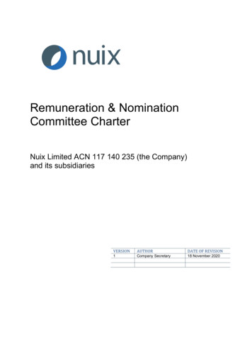
Figure 1. A completed kit, open to show the contents, as installed in a USPSmodel delivery vehicle. The three smartphones as mounted in the lid are levelwith the window and windshield for maximum signal penetration when the caseis closed. The spectrum sensor is located at the top left with a red LED, with theMiFi for sensor data communication below that. Both are positioned in the foaminterior. A single monopole RF antenna for the spectrum sensor is visible at thetop, on the outside of the box. A small GPS antenna for the spectrum sensor isalso mounted at the top but is not fully visible in this image. The power cablesfor the smartphones and MiFi are shown. These cables fit cleanly in the spacebetween the smartphones and the interior foam when the lid is closed.6
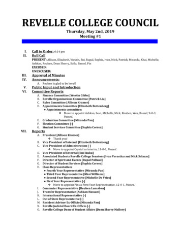
Figure 2. The completed kit, from the bottom, shows the 12V powerconnection to the USPS vehicle.Procurement. After completing the design of the kits, Commission staff initiated the procurementprocess to obtain the smartphones, cases, and power accessory equipment. Staff conducted the requiredcontracting market research, identified available equipment, and worked with providers to obtainsmartphones and data plans. Staff entered into an agreement with the University of Notre Dame to obtainthe most recent version of its RadioHound spectrum sensors to use in the testing.Determining equipment placement. Over the course of several weeks, with the procurement processunderway, the Commission staff worked with USPS to determine where and how to mount the kits ineach USPS vehicle. USPS informed the Commission that Long-Life Vehicles (LLVs) and 2-Ton truckswould be used for the pilot testing and permitted access by staff to a USPS vehicle maintenance facility tocoordinate and test possible mounting locations. The choice of possible locations was driven by safetyand space limitations, as well as radio signal reception considerations.For LLV vehicles, Commission staff considered several locations, including the passenger side bulkhead,underneath the mail tray table, and under and behind the driver’s seat. Commission staff assessed howwell each location would allow reception of radio signals and minimize signal penetration losses. Forexample, Commission staff analyzed whether each location would allow the testing equipment to not begreatly shielded by the vehicle body. Higher locations that were in view of windows were desirable.Staff also considered whether each location would interfere with operation of the vehicle or mail deliveryactivities. Staff needed to confirm that installation of the equipment would not block the driver’s viewout of the vehicle or block the ingress or egress out of the vehicle, and that the equipment would notoccupy areas used to stack and store the mail within the vehicle. Staff also assessed the feasibility ofsecuring the kit in each location so that there would be no danger of its becoming a dangerous projectilein the event of an accident or other sudden stop. Based on all these considerations, staff identified andthen ranked possible mounting locations based on both the vehicle operational requirements as well as theneed to optimize RF performance. Staff discussed the ranked proposed locations, and USPS engineering7
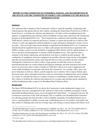
staff made the final selections.It was determined that installation of the kits in the passenger side bulkhead was the preferred approachbecause it would place the radio sensors near the window of the vehicle, thereby ensuring good signalreception and minimizing signal penetration losses. The testing equipment could be mounted easily in thebulkhead location and installation in the bulkhead location did not interfere with operation of the vehicleor mail delivery activities. For the 2-Ton truck, the testing equipment was also mounted in the passengerside position and affixed to a handrail.Figure 3. The USPS LLV. 1616Photographed by user Coolcaesar on December 24, 2005, CC BY-SA d 1172110.8
Figure 4. The USPS 2-Ton truck.USPS engineering and safety inspection. Once Commission staff received the component parts for eachkit, they began assembling the kits. When they completed assembly on the first kit, it was shipped to theUSPS Engineering Facility in Merrifield, Virginia, for an engineering and safety inspection. During theinspection, USPS staff installed the assembled kit in a test vehicle in the Commission’s preferredmounting location (i.e., the passenger side bulkhead). This installation consisted of mounting three boltsthrough the back of the protective case for the kit and then through the passenger side bulkhead in anLLV. Electrical power to the kit was provided by running an electrical wire from the vehicle’s battery inthe engine compartment through the firewall of the vehicle. This included installation of relay circuitrythat enabled the electrical power to go on and off as the vehicle key was turned on and off. This ensuredthat the kit would not drain the vehicle battery when the vehicle was turned off. The connection wascompleted by applying the mating connector so that it could be attached properly to the equipment kit.The USPS engineering and safety inspection included an assessment of (1) whether the kit drainedexcessive battery power from the vehicle battery; (2) whether the mounting of the kit was secure enoughto prevent it from loosening and becoming a projectile risk inside the vehicle; and (3) whether the kit wasmounted in a manner that did not obstruct the driver’s vision. USPS began its inspection and review onor about March 15, 2021, and approved the kits for installation on April 12, 2021.9
Figure 5. This picture shows the kit mounted in an LLV.Speed testing and remote-control apps (Smartphones Only).Commission staff tested several speed test applications, assessing how often each application performedspeed tests, the metrics each application reported, the consistency of each application’s performance, howwell the application worked with macros and remote access software, and how the application allowedretrieval of test results.17Based on its review, staff chose to download for use on the smartphone devices several speed testapplications during the pilot testing: 1) the FCC Speed Test app, an active speed-test app that measuresdownload and upload speeds; 2) Cell Audit, another active speed-test app developed by SamKnows (theFCC’s Speed Test app vendor) to measure download and upload speeds; and 3) SigCap, a passive sensingapp developed by researchers at the University of Chicago, that collects signal strength and frequency ofoperation and identifies the cellular and Wi-Fi signals the smartphone receives. Based on internal testing,staff chose to use both active speed-test apps and the passive sensing app to provide a complete picture ofbroadband coverage. The active speed-test apps provided consistent download and upload data ratemeasurements at regular time intervals. The passive sensing app recorded consistent measurements of theradio performance metrics through the Application Programming Interface on the smartphones every tenseconds, from which data staff could extract information about the signal strength of not only the primaryspectrum channel but also all of the secondary and neighboring channels from the serving cell and othercells (including the bandwidths of channels being aggregated).Staff also conducted extensive testing to choose a commercially available remote-control app to be able to17Macros are programmed steps that were used to automate phone operation.10
remotely control each smartphone. A critical implementation challenge for the pilot testing, as well as forbeing able to scale the pilot to a greater number of vehicles, was the imperative to run the testing appswithout requiring any involvement from USPS employees. The objective for Commission staff was to beable to remotely control the operation of the smartphones in each kit to turn the testing apps on and offduring the day and to monitor whether the smartphones were charging and transmitting data as thevehicles traveled over USPS delivery routes. During field operation, the intent was that staff would haltspeed testing on evenings and weekends to reduce the power consumption so that the batteries in eachsmartphone would not fully discharge (and as noted below, even with these measures, the initial testinguncovered serious power supply problems that drained smartphone batteries and required manual restartsof selected devices by Commission staff ).The remote-control app allowed FCC staff to control the operation of the smartphones and to review andmonitor performance of the smartphones and applications in real time. In addition to the remote-controlapp, staff installed software on the smartphones that enabled them to develop scripts to automatically turnon and off the testing apps on each smartphone based on time of day and similar criteria. The scriptswould start and stop speed tests as a function of time and as a function of application of 5V chargingpower to the mobile device and would repeat speed test measurements at specific intervals. The scriptsalso checked the smartphones continuously to see that the applications were running and, if they were notrunning, to turn them back on. The software was an essential element of automating the testing process asstaff used it to revise the apps’ default settings to perform tests during defined periods each day. Thespectrum sensors were programmed with their own scripts to take spectrum signal strength measurementsat regular intervals.Assembly of kits. Over the course of three weeks, staff completed the loading of the speed test andremote-control software on all of the test smartphones, and assembled the remaining kits. Five of theseven completed kits consisted of a protective case with three smartphones, a spectrum sensor, MiFidevice, and power accessories, including a DC converter and USB cables, and a lock to secure thecontents. The two remaining kits contained the same equipment except for the spectrum sensor due tounavailability of the Notre Dame sensors for these kits. Commission staff modified each protective caseto house the equipment and to provide a means of connecting power wires to USPS vehicles. Staff alsomodified each case to attach antennas to allow operation of the spectrum sensor. While the kit’s initialdesign had two RF antennas mounted on the top of the kit for the spectrum sensor, staff subsequentlydetermined that the spectrum sensor needed only one RF antenna. The RF antenna and one GlobalPositioning System antenna were attached to the outside of each case for the spectrum sensor. Staffriveted a flat piece of metal to the top of each case and attached the antennas to each case via magnets.Additionally, to ensure that the testing equipment did not overheat in the case, staff drilled ventilationholes in each kit.The radio transmitters in each case consist of the smartphones, the MiFi unit, and the Wi-Fi dongle that isattached to the spectrum sensor. The smartphones transmit and receive cellular signals as they measurethe performance of each cellular network. The MiFi unit transmits and receives cellular signals andconnects to the sensor device via a Wi-Fi data connection. The spectrum sensors use these MiFi units totransmit data back to servers at a predefined time interval. A DC converter in each kit produces a 5VDC output to the 4 USB (2 Amps each) connectors in each case. When the kit is turned on, the converterprovides a slow charge rate for all connected battery-powered devices. The DC power is applied througha cannon connector socket that is fed through a 5-amp automotive slow blow fuse stored underneath theprotective foam in the case. Following the fuse, the voltage is applied to the DC converter. From there,11
all connections to the internal devices are made via commercial USB cables and connectors. Based onthis configuration, the devices in the kit only receive battery charge when the USPS vehicle ignitionswitch is turned on or in the accessory position.Once the remaining kits were fully assembled, they were shipped to USPS facilities in Colorado forinstallation in USPS vehicles. USPS and Commission staff completed installation of the kits in sevenLLV vehicles.Data collection route plan. The Commission and USPS coord
Institute,13 a MiFi (mobile Wi-Fi) device wirelessly connected to the spectrum sensor and used by the sensor to transmit data back to servers managed by the University of Notre Dame, and power components sufficient to maintain a charge to the smartphones and to power the spectrum sensor and MiFi device (hereinafter "kit" or "equipment kit