Transcription
HoshizakiHoshizaki America, Inc.Self-Contained ADDS“A Superior Degreeof Reliability”INSTRUCTION MANUALwww.hoshizaki.comIssued: 3-10-2006Revised: 7-1-2011
IMPORTANTOnly qualified service technicians should install, service, or maintain theicemaker. No installation, service, or maintenance should be undertaken untilthe technician has thoroughly read this Instruction Manual. Likewise, the owner/manager should not proceed to operate the icemaker until the installer hasinstructed them on its proper operation. Failure to install, operate, and maintainthe equipment in accordance with this manual may adversely affect safety,performance, component life, and warranty coverage.Hoshizaki provides this manual primarily to assist qualified service technicians in theinstallation, maintenance, and service of the icemaker.Should the reader have any questions or concerns which have not been satisfactorilyaddressed, please call, write, or send an e-mail message to the Hoshizaki TechnicalSupport Department for assistance.HOSHIZAKI AMERICA, INC.618 Highway 74 SouthPeachtree City, GA 30269Attn: Hoshizaki Technical Support DepartmentPhone: 1-800-233-1940 Technical Support(770) 487-2331Fax: 1-800-843-1056(770) 487-3360E-mail: techsupport@hoshizaki.comWeb Site: www.hoshizaki.comNOTE: To expedite assistance, all correspondence/communication MUST include thefollowing information: Model Number Serial Number Complete and detailed explanation of the problem.2
IMPORTANTThis manual should be read carefully before the icemaker is installed andoperated. Only qualified service technicians should install, service, andmaintain the icemaker. Read the warnings contained in this booklet carefully asthey give important information regarding safety. Please retain this booklet forany further reference that may be necessary.CONTENTSImportant Safety Information. 4I. Specifications. 5A. Construction. 5B. Electrical Data. 6C. Dimensions/Connections. 71. AM-50BAE. 72. AM-50BAE-DS. 83. AM-50BAE-AD. 94. AM-50BAE-ADDS. 10II. Installation and Operating Instructions.11A. Checks Before Installation.11B. Location.111. General.112. Built-In Installation Site. 12C. Door. 131. AM-50BAE, AM-50BAE-AD. 13a) Hinge Reversal. 132. AM-50BAE-DS, AM-50BAE-ADDS. 15a) Overlay Panel Fabrication and Attachment. 15D. Setup. 23E. Electrical Connection. 23F. Water Supply and Drain Connections. 24G. Final Checklist . 25H. Startup. 26III. Cleaning and Maintenance. 27A. Cleaning and Sanitizing Instructions. 271. Cleaning Solution. 272. Cleaning Procedure. 273. Sanitizing Solution. 294. Sanitizing Procedure. 29B. Maintenance. 32C. Preparing the Icemaker for Long Storage. 333
Important Safety InformationThroughout this manual, notices appear to bring your attention to situations which couldresult in death, serious injury, or damage to the unit.WARNINGIndicates a hazardous situation which could result in death orserious injury.CAUTIONIndicates a situation which could result in damage to the unit.IMPORTANTIndicates important information about the use and care of theunit.WARNINGThis icemaker should be destined only to the use for which it has beenexpressly conceived. Any other use should be considered improper andtherefore dangerous. The manufacturer cannot be held responsible for injury ordamage resulting from improper, incorrect, and unreasonable use.To reduce the risk of death, electric shock, serious injury, or fire, followbasic precautions including the following: This unit requires an independent power supply. See the nameplate forproper voltage and breaker/fuse size. Failure to use a proper breaker or fusecan result in a tripped breaker, blown fuse, or damage to existing wiring. Thiscould lead to heat generation or fire. THIS UNIT MUST BE GROUNDED: This unit is equipped with a 3‑pronggrounding plug to reduce the risk of potential shock hazards. It must beplugged into a properly grounded, independent wall outlet. If the outlet is a2-prong outlet, it is your personal responsibility to have a qualified electricianreplace it with a properly grounded, independent 3-prong wall outlet. Do notremove the ground prong from the power cord and do not use an adapterplug. Do not use an extension cord. Make sure the control switch is in the "OFF" position before plugging in orunplugging the unit to reduce the risk of electric shock. Do not use a unit with a damaged power cord. The power cord should not bealtered, jerked, bundled, weighed down, pinched, or tangled. Such actionscould result in electric shock or fire. To unplug the unit, be sure to pull theplug, not the cord, and do not jerk the cord. To reduce the risk of electric shock, do not touch the plug or control switchwith damp hands. This unit should be disassembled or repaired only by qualified servicepersonnel to reduce the risk of electric shock, injury, or fire. Do not make any alterations to the unit. Alterations could result in electricshock, injury, fire, or damage to the unit.4
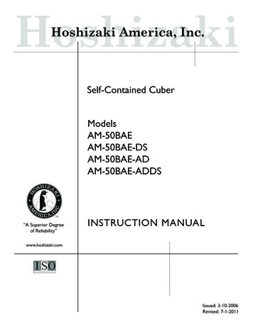
I. SpecificationsA. ConstructionTop PanelIce MakingMechanismBin ControlThermostatBulbScoop HolderSlopeMagnetCatchFront PanelControl SwitchDoorPower CordLouver5
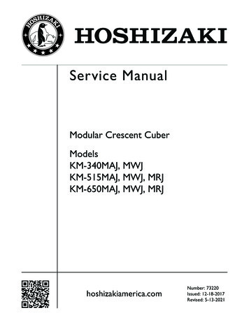
B. Electrical DataHOSHIZAKI ICE MAKERMODEL NUMBERSERIAL NUMBERAC SUPPLY VOLTAGEAMPERESDESIGN PRESSUREREFRIGERANTAM-50BAE115-120/60/13.4 AMPSHI-240PSI LO-120PSI134a 4.2 OZ.MOTOR-COMPRESSOR THERMALLY PROTECTEDAPPROVED FOR OUTDOOR USEHoshizaki America, Inc.Peachtree City, GAwww.hoshizaki.comFor certification marks, see the nameplatein the storage bin.Note: Only the "MODEL NUMBER" is replaced for AM-50BAE-DS, AM-50BAE-AD, andAM-50BAE-ADDS.The nameplate provides electrical and refrigerant data. The nameplate is located in thestorage bin.We reserve the right to make changes in specifications and design without prior notice.6
C. Dimensions/ConnectionsUnits: mm [in.]1. AM-50BAE7
Units: mm [in.]2. AM-50BAE-DS8
Units: mm [in.]3. AM-50BAE-AD9
Units: mm [in.]4. AM-50BAE-ADDS10
II. Installation and Operating InstructionsWARNING1. This icemaker must be installed in accordance with applicable national, state,and local codes and regulations.2. CHOKING HAZARD: Ensure all components, fasteners, and thumbscrewsare securely in place after installation. Make sure that none have fallen intothe storage bin.A. Checks Before Installation Visually inspect the exterior of the shipping container and immediately report anydamage to the carrier. Upon opening the container, any concealed damage should alsobe immediately reported to the carrier. Remove the shipping carton, tape, and packing material. If any are left in the icemaker,it will not work properly. Remove the package containing the accessories. Remove the protective plastic film from the panels. If the icemaker is exposed to thesun or to heat, remove the film after the icemaker cools. See the nameplate on the left side panel, and check that your voltage suppliedcorresponds with the voltage specified on the nameplate.B. Location1. GeneralThis icemaker is approved for indoor or outdoor use.CAUTION1. Normal operating ambient temperature should be within 45 F to 100 F (7 Cto 38 C); Normal operating water temperature should be within 45 F to 95 F(7 C to 35 C). Operation of the icemaker, for extended periods, outside ofthese normal temperature ranges may affect icemaker performance.2. This icemaker will not work at sub-freezing temperatures. To preventdamage to the water supply line, drain the icemaker if the air temperature isgoing to go below 32 F (0 C). See "III.C. Preparing the Icemaker for LongStorage."For best operating results: The icemaker should not be located next to ovens, grills, or other high heat producingequipment. The location should provide a firm foundation for the icemaker. This icemaker requires no side or top clearance. But allow enough space at rear forwater supply and drain connections and at least 15" (38 cm) clearance at front.11
2. Built-In Installation SiteCAUTION1. Do not let the weight of the counter rest on the icemaker.2. Do not install the icemaker in a corner where the door will interfere with otherequipment or where the icemaker cannot be pulled out for service.Installation SpaceModelHeightAM-50BAEAM-50BAE-DS34" (864 mm) minimumAM‑50BAE‑ADAM‑50BAE‑ADDS32" (814 mm) minimumWidthDepth15" (381 mm) minimum24" (610 mm) minimumBetween Two CabinetsAM-50BAEAM-50BAE-DSMin. 34"(864 mm)AM-50BAE-ADAM-50BAE-ADDSMin. 32"(814 mm)Min. 15"(381 mm)Between a Cabinet andthe End of a CounterAM-50BAEAM-50BAE-DSMin. 34"(864 mm)AM-50BAE-ADAM-50BAE-ADDSMin. 32"(814 mm)Min. 15"(381 mm)Support: Do notlet the weight ofthe counter reston the icemakerIn a CornerBetween a Cabinet anda Wall or Tall Cabinet". 23 m)niM 4m(58Secure: Do notlet the weight ofthe counter reston the icemakerOven12Icemaker
C. Door1. AM-50BAE, AM-50BAE-ADa) Hinge ReversalIf you would like to reverse the door hinges, follow the steps below. Otherwise, skip tosection "II.D. Setup."1) While maintaining a hold on the door, remove the hinge stop pin from hinge (B). Pullout the bottom of the door slightly and gently remove the door from hinge (A). SeeFig. 1.Hinge (B)Hinge (A)Fig. 1Hinge Stop Pin2) Remove the 2 screws securing the top panel, then lift it off. See Fig. 2.Top PanelScrewsFig. 23) Remove hinge (A) and the bracket from the right side of the unit and the top brace fromthe left side. Rotate hinge (A) to position the gasket notch to the inside, then fastenhinge (A) and the bracket to the left side and the top brace to the right side. See Fig. 3.BracketScrewHinge (A)ScrewTop BraceGasket Notch13Fig. 3
4) Remove hinge (B) from the right side of the unit and the 2 filler screws from the leftside. Attach the 2 filler screws to the right side and attach hinge (B) to the left side. SeeFig. 4.5) Rotate the top panel 180 from its previous position. This brings the notch that waspreviously in the right rear to the left front. See Fig. 5. Hook the rear part of the panelon the body, then secure the front with the 2 screws removed in step 2.Top PanelScrewsNotchHinge (B)FillerScrewsFig. 4Fig. 56) Remove the 2 screws attaching the door handle and also remove the other 2 screwsindicated in the illustration. Use 2 of the screws to attach the handle to the other side ofthe door and attach the other 2 screws in the remaining 2 holes. See Fig. 6.7) Attach the door to hinge (A), then continue to maintain a hold on the door. Screw thehinge stop pin into hinge (B) until it is tight. See Fig. 7.DoorHandleHinge (B)ScrewsFig. 6Hinge Stop PinFig. 714
2. AM-50BAE-DS, AM-50BAE-ADDSa) Overlay Panel Fabrication and AttachmentIMPORTANTThe overlay panel must be crafted by a professional cabinet maker to ensurequality results.(1) PartsEnsure that all parts required for the overlay panel assembly are contained in theaccessories bag.Overlay Panel PartsNo. Description1Part NumberQty.1Threaded Wood Insert4A4004-0162T2 Screw 4 8 SS7P32-040833Pan Head Screw M4 25 SS7C12-042544Truss Head Screw M4 8 SS7C32-040825Canoe Clip4A0629-0226Sheet Metal Bracket4A3998-0112361545
(2) Overlay Panel SpecificationUse the specification that applies to your icemaker (AM-50BAE-DS or AM-50BAE-ADDS)and the directions that follow to prepare your overlay panel.))()()()(()())()()(((a) AM-50BAE-DSAM-50BAE-DS Overlay Panel SpecificationOverlay Panel Height29 17/32" (750 mm)Overlay Panel Width14 13/16" (376 mm)Overlay Panel Thickness5/8" (16 mm) minimum; 3/4" (19 mm) maximumOverlay Panel and Door Weight (total)20 lb. (9 kg) maximum16
))()()()(()())()()(((b) AM-50BAE-ADDSAM-50BAE-ADDS Overlay Panel SpecificationOverlay Panel Height27 9/16" (700 mm)Overlay Panel Width14 13/16" (376 mm)Overlay Panel Thickness5/8" (16 mm) minimum; 3/4" (19 mm) maximumOverlay Panel and Door Weight (total)20 lb. (9 kg) maximum17
(3) Fabrication of Overlay PanelFabricate the overlay panel as outlined in the applicable specification on the previouspages and the instructions below.1) Rout a channel at the bottom of the overlay panel to the proper dimensions. See "(C)Routed Area" in the specification diagram and Fig. 8.2) Drill six 1/4" diameter (hardwood may require slightly larger diameter) holes 3/8"(10 mm) deep in the locations designated. See "(A) Threaded Inserts" and "(B)Threaded Inserts" in the specification diagram and Fig. 9.CAUTIONUse care when drilling holes for mounting hardware. All drilled holes must bestraight and drilled to the correct diameter and depth.HolesHolesRouted ChannelFig. 9Fig. 83) Screw the 6 threaded wood inserts into the 1/4" holes drilled in the previous step. Makesure that the inserts are threaded straight and that the tops of the inserts are flush tothe overlay panel surface. Otherwise, the overlay panel cannot be properly fastened tothe door.4) Mount the door handle hardware. Hoshizaki recommends that the door handlehardware be mounted on the edge opposite of the door hinge side (optional hingereversal is covered in step 6). Countersunk screw heads are required to ensure that thehardware fasteners do not interfere with the overlay panel fitting flush with the door.5) While maintaining a hold on the door, remove the hinge stop pin from hinge (B). Pull outthe bottom of the door slightly and gently remove the door from hinge (A). See Fig. 10.If you are leaving the door right-hinged, skip to step 7. If you would like to reverse thedoor hinges, proceed to step 6.Hinge (B)Fig. 10Hinge (A)Hinge Stop Pin18
6) If you would like to reverse the door hinges, do the following:a) Contact your local distributor to purchase Hoshizaki Kit HS‑0229. The kit contains"hinge (A)-left."b) Remove the 2 screws securing the top panel, then lift it off. See Fig. 11.c) Remove hinge (A)-right and the bracket from the right side of the unit. Set asidehinge (A)‑right; it is not needed. Remove the top brace from the left side. Fastenhinge (A)-left and the bracket to the left side and the top brace to the right side. SeeFig. 12.Note: When on the proper side, the gasket notch for hinge (A) is to the inside.Top PanelScrewsBracketScrewHinge (A)-LeftScrewTop BraceGasket NotchFig. 11Fig. 12Hinge (A)-RightNot Neededd) Remove hinge (B) from the right side of the unit and the 2 filler screws from the leftside. Attach the 2 filler screws to the right side and attach hinge (B) to the left side.See Fig. 13.e) Rotate the top panel 180 from its previous position. This brings the notch that waspreviously in the right rear to the left front. See Fig. 14. Hook the rear part of thepanel on the body, then secure the front with the 2 screws removed in step 6a.Top PanelScrewsNotchHinge (B)FillerScrewsFig. 13Fig. 14f) Remove hinge (C1) from the top right part of the door, flip it and reattach to thebottom left. Remove hinge (C2) from the bottom right part of the door, flip it andreattach to the top left. See Fig. 15. Proceed to step 7.ScrewsHinge (C2)Fig. 15Hinge (C1)Screws19
7) Remove the bushings from hinge (C1) and hinge (C2) (the hinges attached to the door).See Fig. 16.8) Remove the gasket from the door. See Fig. 17.BushingGasketHingeFig. 17Fig. 169) Temporarily fasten the overlay panel to the door using 2 of the M4 25 pan head screwsprovided. See Fig. 18.CAUTIONEnsure that the back surface of overlay panel is flat before attaching.10) Mark the centerpoint of the hinge (C1) and hinge (C2) holes that extend over theoverlay panel. See Fig. 19.HingeMark the center point.ScrewsDoorOverlay PanelFig. 18Fig. 1911) Remove the overlay panel from the door.12) Drill 3/8" diameter holes 1/4" (7 mm) deep where you marked on the overlay panel toaccommodate the hinge (C1) and hinge (C2) bushings.20
(4) Attachment of Overlay Panel to Door1) Fasten the sheet metal bracket to the overlay panel using the two M4 8 truss headscrews provided. Snug the screws, but do not tighten. See Fig. 20.2) Temporarily fasten the overlay panel to the door using 2 of the M4 25 pan head screwsprovided. See Fig. 21.Overlay PanelScrewsSnug the screws,but do not tighten.Sheet Metal BracketFig. 20Fig. 213) Adjust the sheet metal bracket so that it is flush with the bottom of the door. SeeFig. 22.4) Remove the overlay panel from the door and tighten the two M4 8 truss head screwssecuring the sheet metal bracket to the overlay panel. See Fig. 23.Overlay PanelTighten the screws.DoorSheet Metal BracketSheet Metal BracketFig. 22Fig. 235) Fasten the overlay panel to the door using the four M4 25 pan head screws provided.Snug the screws, but do not tighten. See Fig. 24.6) Fasten the sheet metal bracket to the bottom of the door with the three T2 screwsprovided. Tighten the screws to the door. See Fig. 25.DoorScrewsSnug the screws,but do not tighten.Sheet Metal BracketOverlay PanelFig. 24Fig. 2521
7) Tighten the four M4 25 pan head screws installed in step 5. See Fig. 26.8) Replace the door gasket in its proper orientation. Reinsert the bushings into hinge (C1)and hinge (C2) (the hinges attached to the door). See Fig. 27.BushingTighten the screws.GasketBushingFig. 26Fig. 279) Attach the door to hinge (A), then continue to maintain a hold on the door. Screw thehinge stop pin into hinge (B) until it is tight. See Fig. 28.10) Insert the 2 canoe clips included in the accessory bag into the holes on top of the door.See Fig. 29.Hinge (B)Canoe ClipsDoorHinge Stop PinFig. 28Fig. 2922
D. Setup1) Position the icemaker in the selected permanent location.2) Level the icemaker from side-to-side and front-to-rear by adjusting the feet.E. Electrical ConnectionWARNING1. Electrical connection must meet national, state, and local electrical coderequirements. Failure to meet these code requirements could result in death,electric shock, serious injury, fire, or severe damage to equipment.2. This unit requires an independent power supply. See the nameplate forproper voltage and breaker/fuse size. Failure to use a proper breaker or fusecan result in a tripped breaker, blown fuse, or damage to existing wiring. Thiscould lead to heat generation or fire.3. THIS UNIT MUST BE GROUNDED: This unit is equipped with a 3-pronggrounding plug to reduce the risk of potential shock hazards. It must beplugged into a properly grounded, independent wall outlet. If the outlet is a2-prong outlet, it is your personal responsibility to have a qualified electricianreplace it with a properly grounded, independent 3-prong wall outlet. Do notremove the ground prong from the power cord and do not use an adapterplug. Failure to follow these instructions may result in death, electric shock, orfire.4. Do not use an extension cord.5. Make sure the control switch is in the "OFF" position before plugging in orunplugging the unit to reduce the risk of electric shock.6. Do not use a unit with a damaged power cord. The power cord should not bealtered, jerked, bundled, weighed down, pinched, or tangled. Such actionscould result in electric shock or fire. To unplug the unit, be sure to pull theplug, not the cord, and do not jerk the cord.7. To reduce the risk of electric shock, do not touch the plug or control switchwith damp hands.8. The GREEN ground wire in the factory-installed power cord is connectedto a screw on the rear panel where the cord enters the unit. If it becomesnecessary to remove or replace the power cord, be sure to connect thepower cord's ground wire to this screw upon reattachment. Usually an electrical permit and services of a licensed electrician are required. The maximum allowable voltage variation is 10 percent of the nameplate rating. For optional drain pump installation, refer to the instruction manual included with thepump.23
F. Water Supply and Drain ConnectionsWARNING1. Water supply and drain connections must be installed in accordance withapplicable national, state, and local regulations.2. Normal operating water temperature should be within 45 F to 95 F (7 Cto 35 C). Operation of the icemaker, for extended periods, outside of thisnormal temperature range may affect icemaker performance.3. To prevent damage to equipment, do not operate the icemaker when thewater supply is off, or if the pressure is below 10 PSIG. Do not run theicemaker until the proper water pressure is reached. A plumbing permit and services of a licensed plumber may be required in some areas. External filters, strainers, or softeners may be required depending on water quality.Contact your local Hoshizaki distributor for recommendations. Water supply inlet is 1/2" female pipe thread (FPT). A minimum of 1/4" nominal IDcopper water tubing or equivalent is required for the water supply line. A water supply line shut-off valve and drain valve should be installed. Water supply pressure should be a minimum of 10 PSIG and a maximum of 113 PSIG.If the pressure exceeds 113 PSIG, the use of a pressure reducing valve is required. Drain outlet is 1/2" FPT. A minimum of 1/2" nominal ID hard pipe or equivalent isrequired for the drain line. Drain line should not be piped directly to the sewer system. An air gap of a minimum of2 vertical inches (5 cm) should be between the end of the drain pipe from the icemakerand the floor drain. For gravity drain installation, drain line must have 1/4" fall per foot (2 cm per 1 m) onhorizontal runs to get good flow. A vented tee connection is also required for properflow. For optional drain pump installation, refer to the instruction manual included with thepump.Minimum 1/4" Nominal IDWater Supply LineShut-Off ValveCopper Water TubingWater Supply Inlet1/2" FPTWater Supply LineDrain ValvePiping to approved drain.Leave a 2‑inch (5-cm) verticalair gap between the end of thepipe and the drain.Drain Outlet1/2" FPTVent Tube2-inch (5-cm)air gapFloorDrainFig. 3024Minimum 1/2"Nominal ID Hard Pipe
G. Final ChecklistWARNINGCHOKING HAZARD: Ensure all components, fasteners, and thumbscrews aresecurely in place after installation. Make sure that none have fallen into thestorage bin.1) Is the icemaker level?2) Is the icemaker in a site where the ambient temperature is within 45 F to 100 F (7 C to38 C) and the water temperature within 45 F to 95 F (7 C to 35 C) all year around?3) Have the shipping carton, tape, and packing material been removed from the icemaker?4) Have all electrical and water connections been made? Do electrical and waterconnections meet all national, state, and local code and regulation requirements?5) Has the power supply voltage been checked or tested against the nameplate rating? Isthe power supply a properly grounded, independent 3-prong wall outlet?6) Are the water supply line shut-off valve and drain valve installed? Has the water supplypressure been checked to ensure a minimum of 10 PSIG and a maximum of 113 PSIG?7) Are all components, fasteners, and thumbscrews securely in place?8) Has the end user been given this instruction manual, and instructed on how to operatethe icemaker and the importance of the recommended periodic maintenance?9) Has the end user been given the name and telephone number of an authorized serviceagent?10) Has the warranty tag been filled out and forwarded to the factory for warrantyregistration?25
H. StartupWARNING1. All parts are factory-adjusted. Improper adjustments may adversely affectsafety, performance, component life, and warranty coverage.2. If the icemaker is turned off, wait for at least 3 minutes before restarting theicemaker to prevent damage to the compressor.3. At startup, confirm that all internal and external connections are free of leaks.1) Open the water supply line shut-off valve.2) Make sure the control switch is in the "OFF" position. Plug the unit into the electricaloutlet. If you have to slide the unit back for a built-in installation, make sure you do notdamage or pinch the water supply, drain connections, or power cord.3) If required by sanitation code in your area, seal the perimeter where the machinetouches the floor with approved caulk compound in a smooth and easily cleanablemanner.4) Move the control switch to the "ICE" position and allow the icemaker to operate for2 minutes. This allows the water tank to fill.5) Move the control switch to the "OFF" position.6) Inside the storage bin, disconnect the suction tube by squeezing the tabs and pullingthe tube clear. See Fig. 31. Allow the water tank to drain.7) Reconnect the suction tube as illustrated. See Fig. 32. Make sure the tabs lock intoplace; a loose fitting may cause a water leak.TabsWater TankTabsSuction TubeSuction TubeDrainFig. 31Fig. 328) Clean the storage bin liner, door liner, and door gasket using a neutral cleaner. Rinsethoroughly after cleaning.9) Move the control switch to the "ICE" position to start the automatic icemaking process.10) To confirm bin control operation, hold ice in contact with the bin control thermostat bulb.The icemaker should stop within 10 seconds. Adjustment may be needed, particularly athigher altitude locations.26
III. Cleaning and MaintenanceWARNING1. CHOKING HAZARD: Ensure all components, fasteners, and thumbscrewsare securely in place after any cleaning or maintenance is done to the unit.Make sure that none have fallen into the storage bin.2. The storage bin is for ice use only. Do not store anything else in the storagebin.3. Keep the area around the icemaker clean. Dirt, dust, or insects in the unitcould cause electrical damage to the equipment or harm to individuals.A. Cleaning and Sanitizing InstructionsHoshizaki recommends cleaning and sanitizing this unit at least once a year. Morefrequent cleaning and sanitizing, however, may be required in some existing waterconditions.WARNING1. To prevent injury to individuals and damage to the icemaker, do not useammonia type cleaners.2. Carefully follow any instructions provided with the bottles of cleaning andsanitizing solution.3. Always wear liquid-proof gloves and goggles to prevent the cleaning andsanitizing solutions from coming into contact with skin or eyes.4. After cleaning and sanitizing, be careful not to leave any cleaning orsanitizing solution in the icemaker.1. Cleaning SolutionIMPORTANTFor safety and maximum effectiveness, use the solution immediately afterdilution.Dilute 5 fl. oz. (148 ml or 10 tbs) of Hoshizaki "Scale Away" with 1 gallon (3.8 l) of warmwater. This is a minimum amount. Make more solution if necessary.2. Cleaning Procedure1) Remove all ice from the evaporator and the storage bin.Note: To remove cubes on the evaporator, move the control switch to the "OFF"position and then move it back to the "ICE" position after 3 minutes. The harvestcycle starts and the cubes will be removed from the evaporator.2) Move the control switch to the "OFF" position.27
3) Inside the storage bin, disconnect the suction tube by squeezing the tabs and pullingthe tube clear. See Fig. 33. Allow the water tank to drain.4) Reconnect the suction tube as illustrated. See Fig. 34. Make sure the tabs lock intopl
www.hoshizaki.com Models AM-50BAE AM-50BAE-DS AM-50BAE-AD AM-50BAE-ADDS Self-Contained Cuber Hoshizaki America, Inc. Issued: 3-10-2006 Revised: 7-1-2011 INST RUCTION MANUAL . 2 IMPORTANT Only qualified service technicians should install, service, or maintain the icemaker. No installation, service, or maintenance should be undertaken until


![March 3rd, 2017 [Manage Archive in Microsoft Outlook 2016]](/img/34/archive-outlook-2016.jpg)