Transcription
HoshizakiHoshizaki America, Inc.Cubelet Icemaker/DispenserModelsDCM-270BAH(-OS)F-A Control Board Models“A Superior Degreeof Reliability”SERVICE MANUALwww.hoshizaki.comNumber: 73202Issued: 5-6-2014Revised: 7-2-2014
WARNINGOnly qualified service technicians should install and service the icemaker. Toobtain the name and phone number of your local Hoshizaki Certified ServiceRepresentative, visit www.hoshizaki.com. No service should be undertaken untilthe technician has thoroughly read this Service Manual. Failure to service andmaintain the icemaker in accordance with this manual will adversely affect safety,performance, component life, and warranty coverage and may result in costly waterdamage. Proper installation is the responsibility of the installer. Product failure orproperty damage due to improper installation is not covered under warranty.Hoshizaki provides this manual primarily to assist qualified service technicians in the serviceand maintenance of the icemaker.Should the reader have any questions or concerns which have not been satisfactorilyaddressed, please call, send an e-mail message, or write to the Hoshizaki Technical SupportDepartment for assistance.Phone: 1-800-233-1940; (770) 487-2331Fax: 1-800-843-1056; (770) 487-3360E-mail: techsupport@hoshizaki.comHOSHIZAKI AMERICA, INC.618 Highway 74 SouthPeachtree City, GA 30269Attn: Hoshizaki Technical Support DepartmentWeb Site: www.hoshizaki.comNOTE: To expedite assistance, all correspondence/communication MUST include thefollowing information: Model Number Serial Number Complete and detailed explanation of the problem.2
IMPORTANTThis manual should be read carefully before the icemaker is serviced. Readthe warnings and guidelines contained in this booklet carefully as they provideessential information for the continued safe use, service, and maintenance of theicemaker. Retain this booklet for any further reference that may be necessary.CONTENTSImportant Safety Information. 5I. Construction and Water Refrigeration Circuit Diagrams. 7A. Construction. 7B. Water/Refrigeration Circuit Diagrams. 8II. Sequence of Operation and Service Diagnosis. 9A. Sequence of Operation Flow Chart. 9B. Service Diagnosis. 10C. Control Board Check. 14D. Bin Control Check. 23E. Float Switch Check and Cleaning. 24F. Diagnostic Tables. 26III. Controls and Adjustments. 29A. Control Board Layout. 30B. LED Lights and Audible Alarm Safeties. 32C. Settings and Adjustments. 331. Default Dip Switch Settings. 332. Bin Control Shutdown Delay (Infrared Sensor) (S1 dip switch 1, 2, 3). 333. Drain Frequency Control (S1 dip switch 4). 334. Continuous Dispensing Timer (S1 dip switch 5 & 6). 345. Bin Control Selector (S1 dip switch 7). 346. Bin Control Shutdown Delay (S1 dip switch 8). 347. Factory Use (S1 Dip Switch 9 & 10). 34D. Switches. 35IV. Removal and Replacement of Components. 36A. Service for Refrigerant Lines. 361. Refrigerant Recovery. 372. Brazing. 373. Evacuation and Recharge (R-404A). 37B. Important Notes for Component Replacement. 38C. Icemaking Unit. 401. Upper Bearing Wear Check . 402. Removal and Replacement of Extruding Head. 413. Removal and Replacement of Auger. 414. Removal and Replacement of Evaporator. 425. Removal and Replacement of Mechanical Seal and Lower Housing . 436. Removal and Replacement of Gear Motor. 453
V. Maintenance. 46VI. Preparing the Icemaker for Periods of Non-Use. 47VII. Disposal. 48VIII. Technical Information. 49A. Specification and Performance Data. 491. DCM-270BAH. 492. DCM-270BAH-OS. 50B. Wiring Diagrams. 511. DCM-270BAH(-OS) . 512. DCM-270BAH(-OS). 524
Important Safety InformationThroughout this manual, notices appear to bring your attention to situations which couldresult in death, serious injury, damage to the appliance, or damage to property.WARNINGIndicates a hazardous situation which could result in death orserious injury.NOTICEIndicates a situation which could result in damage to theappliance or property.IMPORTANTIndicates important information about the use and care of theappliance.WARNINGThe appliance should be destined only to the use for which it has been expresslyconceived. Any other use should be considered improper and therefore dangerous.The manufacturer cannot be held responsible for injury or damage resulting fromimproper, incorrect, and unreasonable use. Failure to service and maintain theappliance in accordance with this manual will adversely affect safety, performance,component life, and warranty coverage and may result in costly water damage.To reduce the risk of death, electric shock, serious injury, or fire, follow basicprecautions including the following: Only qualified service technicians should install and service the appliance. The appliance must be installed in accordance with applicable national, state, andlocal codes and regulations. The appliance requires an independent power supply of proper capacity. See thenameplate for electrical specifications. Failure to use an independent power supplyof proper capacity can result in a tripped breaker, blown fuse, damage to existingwiring, or component failure. This could lead to heat generation or fire. THE APPLIANCE MUST BE GROUNDED: The appliance is equipped with aNEMA 5-15 three‑prong grounding plugto reduce the risk of potential shockhazards. It must be plugged into a properly grounded, independent 3-prong walloutlet. If the outlet is a 2-prong outlet, it is your personal responsibility to have aqualified electrician replace it with a properly grounded, independent 3-prong walloutlet. Do not remove the ground prong from the power cord and do not use anadapter plug. Failure to properly ground the appliance could result in death or seriousinjury. Do not use an extension cord. To reduce the risk of electric shock, do not touch the control switch or plug with damphands. Make sure the control switch is in the "OFF" position before plugging in orunplugging the appliance. Do not use an appliance with a damaged power cord. The power cord should notbe altered, jerked, bundled, weighed down, pinched, or tangled. Such actions couldresult in electric shock or fire. To unplug the appliance, be sure to pull the plug, notthe cord, and do not jerk the cord.5
WARNING, continued Do not make any alterations to the appliance. Alterations could result in electricshock, injury, fire, or damage to the appliance. Do not place fingers or any other objects into the ice discharge opening. The appliance is not intended for use by persons (including children) with reducedphysical, sensory, or mental capabilities, or lack of experience and knowledge,unless they have been given supervision or instruction concerning use of theappliance by a person responsible for their safety. Young children should be properly supervised around the appliance. Do not climb, stand, or hang on the appliance or appliance door or allow children oranimals to do so. Serious injury could occur or the appliance could be damaged. Do not use combustible spray or place volatile or flammable substances near theappliance. They might catch fire. Keep the area around the appliance clean. Dirt, dust, or insects in the appliancecould cause harm to individuals or damage to the appliance.NOTICE Follow the water supply, drain connection, and maintenance instructions carefully toreduce the risk of costly water damage. In areas where water damage is a concern, install in a contained area with a floordrain. Install the appliance in a location that stays above freezing. Normal operatingambient temperature must be within 45 F to 100 F (7 C to 38 C). Do not leave the appliance on during extended periods of non-use, extendedabsences, or in sub-freezing temperatures. To properly prepare the appliance forthese occasions, follow the instructions in "VI. Preparing the Appliance for Periods ofNon‑Use." Do not place objects on top of the appliance. The storage bin is for ice use only. Do not store anything else in the storage bin.6
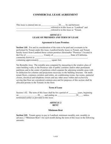
I. Construction and Water Refrigeration Circuit DiagramsA. ConstructionDCM-270BAHDCM-270BAH-OS7
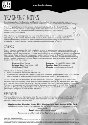
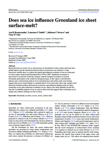
B. Water/Refrigeration Circuit DiagramsDCM-270BAH(-OS)BinInlet Water ValveWaterSupplyReservoirWater LevelFloatSwitchOverflowEvaporatorBin DrainHoseThermostaticExpansion ValveEvaporator WaterSupply HoseTo DrainGear MotorTo DrainDrain ValveDispense Water ValveDrierFanHigh-Pressure SwitchAir-Cooled CondenserCompressorRefrigeration CircuitWater Circuit8
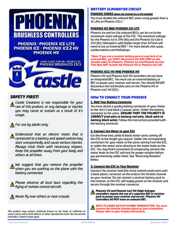
Maximum90 seconds5 sec.5 minutesTo bypass, press the"SERVICE" button afterGM starts.2. Ice Purge Cycle9(S1 dip switch 4)3. 1-in-12 Drain Cycle& Restart (optional)2. Bin ControlShutdown & RestartWV energizedFT starts (90 sec.)6 to 10 sec.2. Ice Purge CycleComp de-energizedFM de-energizedGM energizedIce level lowered3. Icemaker RestartUFS openLFS openFT starts (90 sec.)WV energizedComp energizedFM energizedGM energizedDV energizedGM de-energizedeededto "1. Fill Cycle" aboveA. Sequence of Operation Flow ChartLegend:BC-bin controlComp-compressorDC-drain cycleDT-drain timerDV-drain valveFM-fan motorFT-fill timer (low water safety)GM-gear motorLFS-lower float switchPT-purge timerUFS-upper float switchWV-inlet water valve1-beep alarm continuesWV energizedGM de-energizedinatesPT termWhen UFS closes,alarm resets and2. Ice Purge Cyclestarts.1-beep alarm soundsPT startsUFS openWV energizedComp de-energizedFM de-energizedGM energizedto "2. Ice Purge Cycle" above4. Icemaker Restart10-min. DT terminatesDV de-energized1-in-12 DT reset3. 10-Minute DrainFT exc90 secondsLow Water Safety90 sec. FT exceeded1-beep alarm sounds90 sec. PT startsLFS closedUFS closedFT terminatesWV de-energizedComp energizedFM energizedGM energizedMaximum90 secondsBC closed(BC large balance plate disengaged)Comp energizedFM energizedGM energized2. Icemaker Off5 minutes3. Freeze Cycle1-in-1 drain cycle. DV energizes for 2 seconds every hour(S1 Dip Switch 4).RefillDoes not affect operation.All Components de-energized1. DT Initiates DCBC open(BC large balanceplate engaged)1. Bin FullLFS closedGM energizedUFS closedFT terminatesWV de-energizedIf Fill 90 sec. FT1-beep alarm soundsWV energizedWhen UFS closesalarm resets and2. Ice Purge Cycle starts.Power Switch "ON"Control Switch in "ICE""POWER OK" LED on1. Startup1. Fill Cycle4. 1-in-12 Drain Cycle - Although the factory default 1-in-1 drain cycleis recommended, a 1-in-12 drain cycle is available. For 1-in-12 draincycle sequence, see "3. 1-in-12 Drain Cycle & Restart (optional).""F-A" Control Board Sequence Flow ChartDCM-270B H(-OS)II. Sequence of Operation and Service Diagnosis
B. Service DiagnosisWARNING The appliance should be diagnosed and repaired only by qualified servicepersonnel to reduce the risk of death, electric shock, serious injury, or fire. Risk of electric shock. Use extreme caution and exercise safe electrical practices. Moving parts (e.g., fan blade) can crush and cut. Keep hands clear. CHOKING HAZARD: Ensure all components, fasteners, and thumbscrews aresecurely in place after the appliance is serviced. Make sure that none have falleninto the storage bin. Make sure all food zones in the appliance are clean after service. For cleaningprocedures, see the instruction manual or the maintenance label.1. Ice Production CheckTo check ice production, remove the front, top, and left side panels. Place a containerunder the spout and dispense all ice from the icemaker. Note: The ice dispense switchtimes out after 20 sec. Re-engage every 20 sec. until bin is empty. Move the controlswitch and power switch to the "OFF" position. Remove the bin top cover. Pour warmwater over the remaining ice. After the ice is removed/melted, place the bin top coverin its original position. Do not secure at this time. Remove the control box cover, thenmove the control switch to the "ICE" position and the power switch to the "ON" position.Once the gear motor starts, press the "SERVICE" button on the control board (locatedin the control box). WARNING! Risk of electric shock. Care should be taken not totouch live terminals. Lift the bin top cover and monitor the evaporator extruding head.WARNING! Keep hands, hair, and loose clothing clear of the agitator rotatinginside of the storage bin. Once ice begins to fill the bin, start a 10 min. timer. After10 min., move the power switch to the "OFF" position. Place an empty container underthe spout and dispense all ice from the icemaker. Note: The ice dispense switch timesout after 20 sec. Re-engage every 20 sec. until bin is empty. Move the power switch tothe "OFF" position. Weigh the ice to establish the batch weight (minus the weight of thecontainer). Multiply the batch weight by 144 for the total production in 24 hr. Replace thecontrol box cover and bin top cover in their original positions and secure. Replace allpanels in their original positions and secure. Move the power switch to the "ON" positionto start the automatic icemaking process.10
2. Diagnostic ProcedureThe diagnostic procedure is a sequence check that allows you to diagnose the electricalsystem and components. Before proceeding, check for correct installation, adequatewater pressure (10 to 113 PSIG), and proper voltage per unit nameplate.Note: When checking high voltage (115VAC), always choose a neutral (W) wire toestablish a good neutral connection. When checking low voltage (24VAC), always choose a neutral (LBU) wire. When checking control board DC voltage (5VDC), always place the red positivetest lead from the multimeter to CB K5 pin closest to CB K4 connector.See "II.C. Control Board Check." To speed up the diagnostic process, the 5-min. ice purge cycle may be bypassedby pressing the "SERVICE" button on the control board after the gear motorstarts. WARNING! Risk of electric shock. Care should be taken not to touchlive terminals.1) Move the power switch to the "OFF" position, then disconnect the power cord from theelectrical outlet. Remove the front, top, and left side panels. Remove the control boxcover.2) Reconnect the power cord into the electrical outlet, then move the power switch to the"ON" position.3) Move the control switch to the "DRAIN" position. CB "POWER OK" LED and "FLUSH"(drain) LED turns on.Diagnosis "POWER OK" LED: Check that CB "POWER OK" LED is on. If not, checkfor 115VAC at control transformer brown (BR) wire to neutral (W). If 115VAC is notpresent, check the power switch, power cord connection, and breaker. If 115VAC ispresent, check control transformer continuity. Replace as needed. Next, check for24VAC at control transformer red (R) wire to neutral (LBU). If 24VAC is not present,check control transformer continuity. Replace as needed. If 24VAC is present, check24VAC 1A fuse. If fuse is good, check for 24VAC at CB K8 #1 (W/R) to CB K8 #2 (LBU).If 24VAC is present and "POWER OK" LED is off, replace CB.Diagnosis DV: If DV does not energize, check for 24VAC at CB K2 #10 (W/DBU) toneutral (LBU). If 24VAC is not present, check control switch continuity. If open while inthe "DRAIN" position, replace control switch. If closed, check for 0VDC at control boardK9 #1 (W/BK) to K9 #2 (W/BK). If 5VDC is present and control switch is closed, replaceCB. If 24VAC is present, check for restricted DV and DV solenoid continuity. Clean orreplace as needed.3) After all of the water has drained, move control switch to the "ICE" position.11
4) Fill Cycle – "WTRIN" LED is on. WV energizes. The 90-sec. low water safety timerbegins. LFS closes. Nothing occurs at this time. The reservoir continues to fill untilUFS closes, terminating the 90‑sec. low water safety timer, starting the 30‑min. freezetimer, and de-energizing WV. Diagnosis: Check that "WTRIN" LED turns on and waterfills the reservoir. If not, check for water supply line shut‑off valve closed, restrictedwater filters, and restricted WV screen. Next, check for 24VAC at CB K2 #8 (W/BR)to neutral (LBU). If 24VAC is not present, replace CB. If 24VAC is present, turn off thepower switch, disconnect the WV wires and check WV solenoid continuity. If open,replace WV. Reconnect WV wires, move the power switch to the "ON" position, thencheck that DV is not leaking by. Check that WV shuts off when UFS closes.Note: Low Water Safety– If UFS remains open 90 sec. after WV energizes, a 1‑beepalarm sounds. This alarm resets automatically once UFS closes.5) Ice Purge Cycle – "GM" LED is on. 5-sec. GM delay timer and 30‑min. freeze timerstart. WV de-energizes and "WTRIN" LED turns off. Once the 5‑sec. GM delay timerterminates, GM and CDR energize. CDR cannot energize unless GM circuit is complete(fuse, internal protector, and windings). Once CDR energizes, CB K9 #5 W/O andCB K9 #6 W/O 5VDC circuit closes and 5-min. ice purge timer starts. See "II.C.3)c.Compressor Delay Relay (5-min. Ice Purge Timer Circuit)." If CDR de‑energizes, CBK9 #5 W/O and CB K9 #6 W/O circuit opens and an 8-beep alarm occurs. See "III.B.LED Lights and Alarm Safeties." Note: To bypass ice purge cycle and go straight tofreeze cycle, press "SERVICE" button on CB during 5-sec. GM delay time.Diagnosis CB: Check that UFS closed, WV LED turned off and WV de‑energized.If UFS is closed, "WV" LED is off, and "GM" LED is off, replace CB. If "GM" LED ison and GM is off, confirm 115VAC at CB K1 #2 (BR) to neutral (W). If 115VAC is notpresent, check for loose connection from power switch. If 115VAC is present, check for115VAC at CB K1 #3 (BK) to neutral (W). If 115VAC is not present, replace CB.Diagnosis GM: If 115VAC is present at CB K1 #2 (BR) to neutral (W), check GM fuse,GM capacitor, GM windings, and GM coupling between auger and GM.Diagnosis CDR: See "II.C.3)c. Compressor Delay Relay (5-min. Ice Purge TimerCircuit)." Once 5-min. ice purge timer terminates, freeze cycle begins.6) Freeze Cycle – "COMP" LED is on. 5-min. ice purge timer terminates or "SERVICE"button pressed. "COMP" LED turns on. "GM" LED remains on. Comp and FM energize.GM and CDR continue. Ice production begins 4 to 6 minutes after Comp energizesdepending on ambient and water conditions. Diagnosis Comp: Check that "COMP"LED is on and that Comp energizes. If "COMP" LED is off, confirm 5-min. ice purgetimer has terminated. Check for 0VDC across CB K9 #3 (W/O) and CB K9 #5 (W/O).If 5VDC is present, CDR contacts are open. Check for 115VAC at CDR #7 (O) to CDR#8 (W). If 115VAC is present, check CDR continuity between CDR #3 (W/O) andCDR #5 (W/O). If open, replace CDR. If closed and "COMP" LED remains off, replaceCB. If "COMP" LED is on and Comp is off, check for 115VAC at each CB X1 brown(BR) wire to neutral (W). If 115VAC is present on one and not the other, replace CB.If 115VAC is present on both, check Comp windings, start relay, and capacitors.Note: If CDR de‑energizes, CB K9 #5 W/O and CB K9 #6 W/O circuit opens, Compde‑energizes and an 8-beep alarm occurs. See "III.B. LED Lights and Alarm Safeties."Diagnosis FM: If FM does not energize, check FM capacitor, windings, and bearings.12
7) Refill Cycle/Low Water Safety – As ice is produced, the water level in the reservoirdrops. UFS opens. Nothing occurs at this time. When LFS opens, WV energizes,90‑sec. low water safety timer (fill timer) starts. Comp, GM, CDR, and FM continue.When UFS closes, WV de-energizes, 90-sec. low water safety timer (fill timer)terminates and 30‑min. freeze timer resets. If UFS remains open 90 sec. after WVenergizes (fill timer exceeded), a 90-sec. shutdown cycle starts. Comp and FMde‑energize and CB signals a 1-beep alarm every 5 sec. 90-sec. ice purge timerstarts. GM and CDR continue to clear ice from the evaporator. 90-sec. purge timerterminates, GM and CDR de‑energize. WV and 1-beep alarm continue until UFS closes.Diagnosis – Check that "WTRIN" LED is on. If not, check LFS. See "II.E. Float SwitchCheck and Cleaning." If LFS is open and "WTRIN" LED is off, replace CB. If "WTRIN"LED is on, check that the reservoir fills. If not, check the water supply line, restrictedwater filters, WV solenoid, restricted WV screen. If WV is energized and refill exceeds90-sec. low water safety timer (fill timer), check DV leaking by or open UFS.See "II.E. Float Switch Check and Cleaning."Note: Each time UFS closes, 30-min. freeze timer starts. The 30-min. freeze timer resetswhen UFS closes again. If UFS does not close again within 30 min., CB shutsdown the unit and sounds a 5-beep alarm every 5 sec. See "II.B. LED Lights andAlarm Safeties."10) Shutdown – Bin fills with ice activating BC microswitch. Within 10 sec. controlboard shutsdown unit. Diagnosis: Check that BC large balance plate is activatedand not sticking. Check BC microswitch continuity. When BC large balance plate isdown (icemaking), BC microswitch is closed. When BC large balance plate is up BCmicroswitch is open. If not, replace BC microswitch. If BC microswitch is open andComp, FM, and GM do not de‑energize, replace CB. See "II.C. Control Board CheckProcedure."Legend: BC–bin control; CB–control board; CDR–compressor delay relay;Comp–compressor; CT–control transformer; DV–drain valve; FM–fan motor;GM–gear motor; LFS–lower float switch; UFS–upper float switch; WV–inlet watervalve13
C. Control Board CheckBefore replacing a CB that does not show a visible defect and that you suspect is bad,always conduct the following check procedure. This procedure will help you verify yourdiagnosis. Before proceeding, check for proper voltage per appliance nameplate. Checkthat the 24VAC 1A fuse and 115VAC 3A GM breaker are good. Check the S1 dip switch settings to assure that they are in the factory default position.For factory default settings, see "III.C.1. Default Dip Switch Settings." S1 dip switch7 determines bin control application. WARNING! Do not adjust S1 dip switch 7 outof the factory default position. This dip switch must be left in the factory defaultposition or the appliance will not operate correctly. When checking for 115VAC high‑voltage (primary), always choose a 115VACneutral (W) to establish a good neutral connection. When checking for 24VAC low-voltage (secondary), always choose a 24VACneutral (LBU) to establish a good neutral connection. If the appliance is in alarm, see"III.B. LED Lights and Audible Alarm Safeties." When checking for 5VDC, use CB red K4 connector pin closest to CB blackK3 connector for DC ground (GND).14
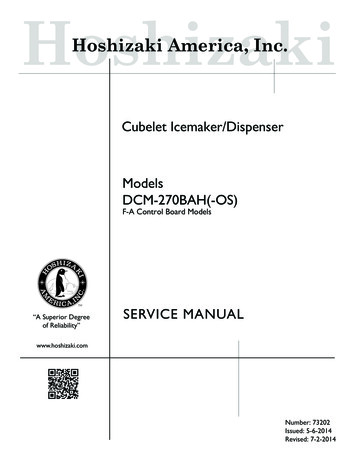
1) Startup-"POWER OK" LED on: Move control switch to "ICE" position, then movepower switch to "ON" position. "POWER OK" LED turns on. "POWER" LED remainson unless power supply is interrupted. NOTICE! Appliance will not start unless thesafety switch is engaged. Diagnosis: Check that "POWER OK" LED is on. If not,check for proper 115VAC supply voltage to CT (main breaker or fuse and power switch).Next, check for proper 24VAC output from CT. Next, check that 1A fuse is good. Checkfor 24VAC from CB K8 connector pin #1 (W/R) to CB K8 connector pin #2 (LBU).If 24VAC is present and "POWER OK" LED is off, replace CB.2) 5VDC Output Checks: There are seven 5VDC circuits on the appliance.a) 3 circuits at CB K9 connector: Control switch "DRAIN" position, high-pressure switch(HPS), and compressor delay relay (CDR).b) 2 circuits at CB K8 connector: Bin control (BC) and float switch (FS upper andlower).c) 2 circuits at CB K7 connector: Ice dispense (push button, and OS sensor), and waterdispense (push button and OS sensor).2a) 5VDC CB K9 Connector: See Fig. 1.5VDC CB K9 ConnectorComponentPin # (Wire Color)Control Switch "DRAIN" Position#1 (W/BK) and #2 (W/BK)High-Pressure Switch (HPS)#3 (Y) and #4 (Y)Compressor Delay Relay (CDR)#5 (W/O) and #6 (W/O)(CDR relay terminals #3 W/O and #5 W/O)Red positive test lead tored K4 connector pin closestto black K3 connectorMultimeter5VDCBlack NegativeTest LeadRed PositiveTest Lead"DRAIN" Position onControl Switch(W/BK)High-Pressure Switch (HPS) (Y)Compressor Delay Relay (CDR)CDR Terminals #3 (W/O) and #5 (W/O)Control Board K9 ConnectorFig. 115
2a) 5VDC CB K9 Connector Continued:a) Control Switch"DRAIN" PositionCB K9 connector pins #1 (W/BK) and #2 (W/BK): "ICE" Position: When the control switch is in the "ICE" position, CB K9 connectorpin #1 and pin #2 are open. 5VDC is present between CB K9 connectorpin #1 (W/BK) and pin #2 (W/BK). If not, confirm 5VDC between pin #1 (W/BK) andCB red K4 connector, pin closest to CB black K3 connector. If 5VDC is not present,replace CB. "DRAIN" Position: When control switch is in the "DRAIN" position, CB K9 connectorpin #1 (W/BK) and pin #2 (W/BK) are closed. 5VDC is present between both CBK9 connector pin #1 (W/BK) and pin #2 (W/BK) to CB red K4 connector, pin closestto CB black K3 connector. If 5VDC is not present, replace CB.b) High-Pressure Switch (HPS)CB K9 connector pins #3 (Y) and #4 (Y): When HPS is closed, 5VDC is presentbetween both CB K9 connector pins #3 (Y) and pin #4 (Y) to CB red K4 connectorpin closest to CB black K3 connector. If 5VDC is not present on pin #3 (Y) or pin#4 (Y), replace CB. If 5VDC is present on CB K9 connector pin #3 (Y) and not on CBK9 connector pin #4 (Y), HPS is most likely open. CB sounds a 3-beep alarm. CheckHPS continuity. If HPS is open and CB is not in alarm, replace CB.c) Compressor Delay Relay (CDR)CB K9 connector pins #5 (W/O) and #6 (W/O): When CDR is de‑energized (GM off),CDR terminals #3 and #5 are open and 5VDC is present between CB K9 connectorpin #5 (W/O) and CB K9 connector pin #6 (W/O). If 5VDC is not present, check CDRcontinuity between terminals #3 and #5. If open, replace CB. When CDR is energized,CDR terminals #3 and #5 close and 0VDC is present between CB K9 connector pin#5 (W/O) and pin #6 (W/O). 5VDC is present between CB K9 connector pin #5 (W/O)to CB red K4 connector pin closest to CB black K3 connector and CB K9 connectorpin #6 (W/O) to CB red K4 connector pin closest to CB black K3 connector. If GM isenergized and CDR terminals #3 & #5 are open, an 8-beep alarm occurs. See "III.B.LED Lights and Audible Alarm Safeties." If CDR terminals #3 and #5 are closedand 0VDC is present between CB K9 connector pin #5 (W/O) and pin #6 (W/O),5-min. Comp delay timer starts. If Comp does not energize after 5-min. delay timerterminates, replace CB.16
2b) 5VDC CB K8 Connector: See Fig. 2.5VDC CB K8 ConnectorComponentPin # (Wire Color)Bin Control (BC)#3 (GY) and #4 (GY)Float Switch (FS)
DCM-270BAH(-OS) F-A Control Board Models Cubelet Icemaker/Dispenser Hoshizaki America, Inc. Number: 73202 Issued: 5-6-2014 Revised: 7-2-2014 SERVICE MANUAL. 2 WARNING Only qualified service technicians should install and service the icemaker. To obtain the name and phone number of your local Hoshizaki Certified Service