Transcription
Service ManualModular Crescent CuberModelsKM-340MAJ, MWJKM-515MAJ, MWJ, MRJKM-650MAJ, MWJ, MRJhoshizakiamerica.comNumber: 73220Issued: 12-18-2017Revised: 5-13-2021
WARNINGOnly qualified service technicians should install and service the appliance. Toobtain the name and phone number of your local Hoshizaki Certified ServiceRepresentative, visit www.hoshizaki.com. No service should be undertaken untilthe technician has thoroughly read this Service Manual. Failure to service andmaintain the appliance in accordance with this manual will adversely affect safety,performance, component life, and warranty coverage. Proper installation is theresponsibility of the installer. Product failure or property damage due to improperinstallation is not covered under warranty.Hoshizaki provides this manual primarily to assist qualified service technicians in theservice of the appliance.Should the reader have any questions or concerns which have not been satisfactorilyaddressed, please call, send an e-mail message, or write to the Hoshizaki TechnicalSupport Department for assistance.Phone: 1-800-233-1940; (770) 487-2331Fax: 1-800-843-1056; (770) 487-3360E-mail: techsupport@hoshizaki.com618 Highway 74 SouthPeachtree City, GA 30269Attn: Hoshizaki Technical Support DepartmentWeb Site: www.hoshizaki.comNOTE: To expedite assistance, all correspondence/communication MUST include thefollowing information: Model Number Serial Number Complete and detailed explanation of the problem.2
IMPORTANTThis manual should be read carefully before the appliance is serviced. Readthe warnings and guidelines contained in this manual carefully as they provideessential information for the continued safe use, service, and maintenance of theappliance. Retain this manual for any further reference that may be necessary.CONTENTSImportant Safety Information. 5I. Construction and Water/Refrigeration Circuit Diagram. 7A. Construction. 71. Air-Cooled Models (MAJ). 72. Water-Cooled Models (MWJ). 83. Remote Models (MRJ). 9B. Water/Refrigeration Circuit Diagram. 101. Air-Cooled Models (MAJ). 102. Water-Cooled Models (MWJ).113. Remote Models (MRJ). 12II. Sequence of Operation and Service Diagnosis. 13A. Sequence of Operation Flow Chart. 131. Operation Flow Chart . 132. Shutdown Flow Chart. 143. Freeze-Time Correction Chart. 15B. Service Diagnosis. 16C. Freeze-Time Correction Cycle (90 min.). 23D. Control Board Check. 25E. Bin Control Check. 261. Bin Control Check. 262. Bin Control Cleaning. 27F. Float Switch Check and Cleaning. 281. Float Switch Check. 282. Float Switch Cleaning. 29G. Thermistor Check. 30H. Control Switch. 30I. Diagnostic Tables. 31J. Freeze-Up Check List. 35III. Controls and Adjustments. 36A. Control Board Layout. 37B. LED Lights and Audible Alarm Safeties. 383
C. Settings and Adjustments. 391. Default Dip Switch Settings. 392. Harvest Time (S4 dip switch 1 & 2). 403. Pump-Out Time/Harvest Time During Pump-Out (S4 dip switch 3 & 4). 404. Pump-Out Frequency Control (S4 dip switch 5). 415. Harvest Pump Time (Harvest Assist) (S4 dip switch 6). 416. Harvest Pump Time (Harvest Assist)/Freeze-Time Correction (S4 dip switch 7). 427. Factory Use (S4 dip switch 8). 428. Freeze Timer (S4 dip switch 9 & 10). 439. Float Switch Selector (S5 dip switch 1). 4310. Refill Counter (S5 dip switch 2 and 3). 4311. Minimum Harvest Time (S5 dip switch 4). 4412. Anti-Slush (S5 dip switch 5). 44IV. Refrigeration Circuit and Component Service Information. 45A. Refrigeration Circuit Service Information. 45B. Component Service Information. 48C. Water Regulating Valve Adjustment (water-cooled model). 49V. Maintenance. 50VI. Preparing the Appliance for Periods of Non-Use. 51VII. Disposal. 53VIII. Technical Information. 54A. Specification and Performance Data Sheets. 541. KM-340MAJ. 542. KM-340MWJ. 553. KM-515MAJ. 564. KM-515MWJ. 575. KM-515MRJ with URC-5F. 586. KM-650MAJ. 597. KM-650MWJ. 608. KM-650MRJ with URC-5F. 61B. Wiring Diagrams . 621. KM-340M J. 622. KM-515M J and KM-650M J. 634
Important Safety InformationThroughout this manual, notices appear to bring your attention to situations which couldresult in death, serious injury, damage to the appliance, or damage to property.WARNINGIndicates a hazardous situation which could result in death orserious injury.NOTICEIndicates a situation which could result in damage to theappliance or property.IMPORTANTIndicates important information about the use and care of theappliance.WARNINGThe appliance should be destined only to the use for which it has been expresslyconceived. Any other use should be considered improper and therefore dangerous.The manufacturer cannot be held responsible for injury or damage resulting fromimproper, incorrect, and unreasonable use. Failure to service and maintain theappliance in accordance with this manual will adversely affect safety, performance,component life, and warranty coverage and may result in costly water damage.To reduce the risk of death, electric shock, serious injury, or fire, follow basicprecautions including the following: Only qualified service technicians should install and service this appliance. The appliance must be installed in accordance with applicable national, state, andlocal codes and regulations. Electrical connection must be hard-wired and must meet national, state, and localelectrical code requirements. Failure to meet these code requirements could resultin death, electric shock, serious injury, fire, or severe damage to equipment. The icemaker requires an independent power supply of proper capacity. See thenameplate for electrical specifications. Failure to use an independent power supplyof proper capacity can result in a tripped breaker, blown fuses, damage to existingwiring, or component failure. This could lead to heat generation or fire. THE ICEMAKER MUST BE GROUNDED. Failure to properly ground the icemakercould result in death or serious injury. Move the control switch to the "OFF" position and turn off the power supply beforeservicing. Lockout/Tagout to prevent the power supply from being turned back oninadvertently. To reduce the risk of electric shock, do not touch the control switch with damphands. Do not make any alterations to the unit. Alterations could result in electric shock,injury, fire, or damage to the unit. The appliance is not intended for use by persons (including children) with reducedphysical, sensory, or mental capabilities, or lack of experience and knowledge,unless they have been given supervision or instruction concerning use of theappliance by a person responsible for their safety.5
WARNING, continued Children should be properly supervised around this appliance. Do not climb, stand, or hang on the appliance or allow children or animals to do so.Serious injury could occur or the appliance could be damaged. Do not use combustible spray or place volatile or flammable substances near theappliance. They might catch fire. Keep the area around the appliance clean. Dirt, dust, or insects in the appliancecould cause harm to individuals or damage to the appliance.Additional Warning for Remote Models THE REMOTE CONDENSER UNIT MUST BE GROUNDED. The power supply andground connection to the remote condenser unit are supplied from the icemaker.Failure to properly ground the remote condenser unit could result in death orserious injury. Move the icemaker control switch to the "OFF" position and turn off the powersupply to the icemaker before servicing the remote condenser unit.Lockout/Tagout to prevent the power supply from being turned back oninadvertently.NOTICE Follow the instructions in this manual carefully to reduce the risk of costly waterdamage. In areas where water damage is a concern, install in a contained area with a floordrain. Install the appliance in a location that stays above freezing. Normal operatingambient temperature must be within 45 F to 100 F (7 C to 38 C). Do not leave the icemaker on during extended periods of non-use, extendedabsences, or in sub-freezing temperatures. To properly prepare the icemaker forthese occasions, follow the instructions in "VI. Preparing the Appliance for Periodsof Non-Use." Do not place objects on top of the appliance. The dispenser unit/ice storage bin is for ice use only. Do not store anything else inthe dispenser unit/ice storage bin.6
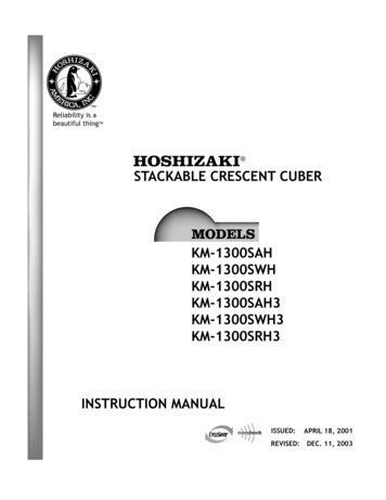
I. Construction and Water/Refrigeration Circuit DiagramA. Construction1. Air-Cooled Models (MAJ)ThermostaticExpansion ValveWater Supply InletSpray TubesHot Gas ValveInlet Water ValveCondenserCleaning ValveControl SwitchHigh-PressureSwitchSplash GuardCheck Valve(water)Fan MotorDrierFloat SwitchWater PumpControl BoxCompressorBin Control and BracketModel Shown: KM-340MAJ7
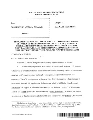
2. Water-Cooled Models (MWJ)ThermostaticExpansion ValveWater Supply InletSpray TubesHot Gas ValveHigh-Pressure SwitchInlet Water ValveWater RegulatingValveCondenserCleaning ValveControl SwitchControl BoxSplash GuardCheck Valve(water)DrierFloat SwitchLiquid Line ValveWater PumpCompressorBin Control and BracketModel Shown: KM-515MWJ8
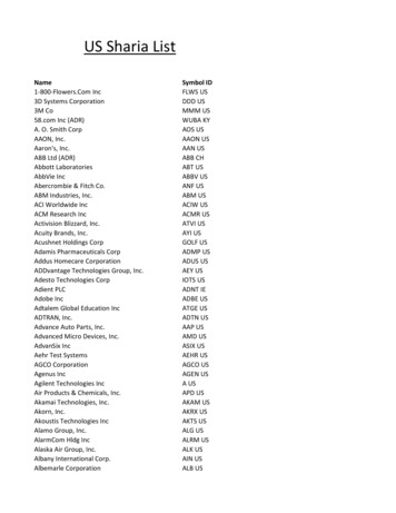
3. Remote Models (MRJ)ThermostaticExpansion ValveSpray TubesWater Supply InletInlet Water ValveJunction BoxEvaporatorHot Gas ValveStainerCleaning ValveHigh-Pressure SwitchControl SwitchReceiver TankSplash GuardCheck Valve(water)DrierFloat SwitchLiquid Line ValveWater PumpCompressorControl BoxCrankcase HeaterBin Control and BracketModel Shown: KM-650MRJ9
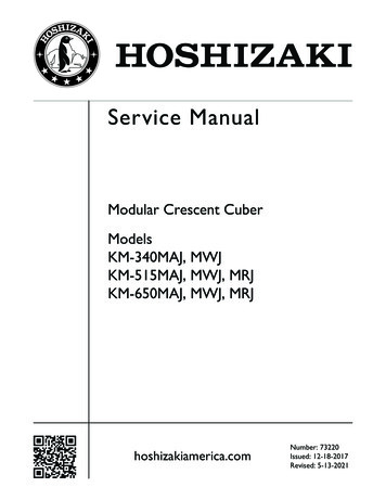
B. Water/Refrigeration Circuit Diagram1. Air-Cooled Models (MAJ)Spray TubesCondenserInlet Water ValveDrierEvaporatorWater SupplyFanHigh-PressureSwitchLiquid Line Valve(KM-515MAJ andKM-650MAJ)ThermistorHeatExchangerSuction LineStrainerWater PumpFloat SwitchHot GasValveWaterTankCompressor Discharge LineDrainFreezePump OutThermostatic Expansion ValveRefrigeration CircuitCheck ValveWater Circuit10
2. Water-Cooled Models (MWJ)Water Regulating ValveCondenserSpray TubesInlet Water ValveDrierEvaporatorWater SupplyLiquid Line tion LineStrainerWater PumpFloat SwitchHot GasValveWaterTankCompressorDrainFreezeDischarge LinePump OutThermostatic Expansion ValveRefrigeration CircuitCheck ValveWater Circuit11
3. Remote Models (MRJ)CondenserFanHeadmaster(C.P.R.)Spray TubesAccessValveInlet Water ValveDrierWater SupplyHigh-PressureSwitchReceiverStrainerLiquid LineEvaporator ValveHeatExchangerThermistorHot GasValveCleaning ValveSuction LineWater PumpFloat SwitchWaterTankDischarge LineDrainFreezePump-OutCompressorThermostatic ExpansionValveRefrigeration CircuitCheck ValveWater Circuit12
13Comp energizedFMR energizedHGV energizedWV energizedFS closedThermistorin controlFS checkComp energizedFMR energizedHGV energizedPM de-energizes for 2 sec.,then reverses for 10/20 sec.FM de-energizedLLV de-energizedFreeze Time Differential Exceeded.Initiate Freeze-Time Correction Cycle.See "II.A.3. Freeze-Time Correction Cycle.Anti-SlushThermistor temperaturereaches 36 F (2.2 C)(5.8 kΩ).PM de-energized for10 sec.FS opens or freezetimer terminatesFS in control Factory set for every 10thcycle(S4 dip switch 5) Pump motor stops for2 sec., then reverses for10/20 sec.(S4 dip switch 3 & 4)4. Pump-Out CycleThe "WASH" position on the control switch is used when cleaning and sanitizing the unit. When in the "WASH" position, power is suppliedto the pump motor. With the cleaning valve closed, the cleaner and sanitizer flow over the outside of the evaporator plate assembly. With thecleaning valve open, the cleaner and sanitizer flow over both the outside and the inside of the evaporator plate assembly.Note: Close the cleaning valve after cleaning and sanitizing are complete, otherwise the unit will not restart when the controlswitch is placed in the "ICE" position.Comp energizedFM energizedFMR energizedPM energizedLLV energizedHGV de-energizedFS closed5-min.minimumfreeze timer incontrol Min. freeze time: 5 min. Max. freeze time: freeze timer setting (S4 dipswitch 9 & 10) Freeze-Time monitoring for Freeze-TimeCorrection starts at 2nd freeze cycle.3. Freeze CycleComponents Energized when the Control Switch is in the "WASH" PositionFS openThermistor temperature reaches48 F (9 C) (3.9 kΩ or less). Harvesttimer starts.PM energizedWV de-energized50 sec.Harvest PumpTimer1 to 3-min. harvest timer incontrol (S4 dip switch 1 & 2) WV time: 6 min. or the length of harvest minus 50 sec.(S4 dip switch 7), whichever is shorter. Do not adjust S4dip switch 7 out of the factory position. Max. harvest time: 20 min.2. Harvest CycleIf FS is open, Comp stops and cycle returns to1-Min. fill.FS openWV energizedFS check1. 1-MinuteFill Cycle1. Operation Flow ChartLegend:BC–bin controlComp–compressorFM–fan motorFMR–fan motor-remoteFS–float switchHGV–hot gas valveLLV–liquid line valvePM–pump motorWV–inlet water valveStartupCycleStepsOperation Flow ChartII. Sequence of Operation and Service DiagnosisA. Sequence of Operation Flow Chart
BC OperationShutdownand Restart14Legend:BC–bin controlBC open (BC actuator paddle engaged)Green "BC CLOSED" LED offYellow "BC OPEN" LED onAll componentsde-energized.2. Icemaker OffBC closed(BC actuator paddle disengaged)Green "BC CLOSED" LED onYellow "BC OPEN" LED offTo 1. 1-Minute Fill CycleIcemaker starts at"1. 1-Minute Fill Cycle."3. Ice Level LoweredControl board retains freeze-time correction count databetween bin control restarts.Yellow "BC OPEN" LED continues. Allcomponents de‑energized.Shutdown Delay: Fill Cycle–15 sec. after activation. Harvest Cycle–At the end of the harvest cycle, or upto 15 sec. into the freeze cycle ifactivated at the end of the harvest cycle. Freeze Cycle– 15 sec. after activation if activated at least15 sec. before the 5-min. short cycleprotection timer terminates.Otherwise, at the end of the next harvestcycle.1. Bin FullShutdown Flow Chart2. Shutdown Flow Chart
15254309349380406427446462345678910Note: When 1st freeze-time correction cycleis initiated, CB "POWER OK" LED startsblinking. On 2nd freeze-time correction cycle,if CB "POWER OK" LED has been reset,CB "POWER OK" LED starts blinking. If CB"POWER OK" had not been reset after 1stfreeze-time correction cycle CB "POWEROK" LED continues to blink.After 3rd freeze‑time correction cycle in36 hours, CB yellow "EXT HARVEST" LEDstarts blinking.Appliance continues to operate and LEDscontinue to blink until ALARM RESET buttonis pressed with power on.DifferentialValue in Sec.Number ofFreeze CyclesFreeze Time Differential Exceeded.Minimum and Maximum Freeze times haveexceeded differential parameters.Freeze-Time Correction function is enabledwhen S4 Dip Switch 7 is in the "ON" position.CB monitors freeze time. After 3 freezecycles, CB compares the minimum andmaximum differential of the 3 freeze cycletimes. Every freeze cycle time after the thirdfreeze cycle time is added to the minimum/maximum calculation.Example: After 8 cycles, if the differentialbetween the shortest cycle (minimum) andthe longest cycle (maximum) is equal to orgreater than 427 sec. a freeze-time correctioncycle is initiated:Comp energizedFMR energizedHGV energizedPM energizedWV energizedAppliance Cycle Reset and Alarm Reset:Cycle Reset: Power Supply or Control Switch Turned Off and On again:Appliance turns off, then re-starts at 1.Fill Cycle.Alarm Reset: CB "ALARM RESET" pressed during or after a freeze-timecorrection cycle with power supply on:Appliance continues cycle with no interruption or reset.CB red "POWER OK" LED blinking:CB red "POWER OK" LED resets to solid.CB yellow "EXT HARVEST" LED blinking:CB yellow "EXT HARVEST: LED turns off.WV energizedComp de-energizedFMR de-energizedHGV de-energizedPM de-energized2. 10-Minute Fill/OverflowAfter 5th 10-Minute Harvest Pump Cycle with WVFreeze-Time Correction Cycle Complete.Go to Step "3. Freeze Cycle" in Operation Flow Chart. Do not adjust S4 dip switch 7 out of the factory position. After step 2 completes 4th sequence (80 min. completed), repeatstep 1 for 5th and final time.1. 10-Minute Harvest Cycle with WVLegend:Comp–compressorFM–fan motorFMR–fan motor-remoteHGV–hot gas valvePM–pump motorWV–inlet water valveStartCycle StepsSteps 1 and 2 repeat4 times (total 80 min.),then step 1 repeats fora 5th time to completeFreeze‑Time CorrectionCycle.2A7664-02 Freeze-Time Correction Flow Chart3. Freeze-Time Correction Chart
B. Service DiagnosisWARNING The appliance should be diagnosed and repaired only by qualified servicepersonnel to reduce the risk of death, electric shock, serious injury, or fire. Risk of electric shock. Control switch in "OFF" position does not de‑energize allloads Use extreme caution and exercise safe electrical practices. Moving parts (e.g., fan blade) can crush and cut. Keep hands clear. Before servicing the appliance, move the control switch to the "OFF" position andturn off the power supply. CHOKING HAZARD: Ensure all components, fasteners, and thumbscrews aresecurely in place after the appliance is serviced. Make sure that none have falleninto the dispenser unit/ice storage bin. Make sure all food zones in the appliance and dispenser unit/ice storage bin areclean after service.The diagnostic procedure is a sequence check that allows you to diagnose the electricalsystem and components. Before proceeding, check for correct installation, proper voltageper nameplate, and adequate water supply. Check CB using the steps in "II.D. ControlBoard Check." Check dip switch settings to assure that S4 dip switches and S5 dipswitches 1 through 5 are in the factory default position. S4 dip switch 1, 2, 3, 4, and 5 arecleaning adjustments and the settings are flexible. For factory default settings, see "III.C.1.Default Dip Switch Settings."Note: When checking high voltage (115VAC), always choose a white (W) neutral wire toestablish a good neutral connection. When checking voltage from the CB K1 connector (10 pin connector), pullCB K1 connector out slightly to allow room for multimeter test leads contact.1) Turn off the power supply, then access the control box. Move the control switch to the"OFF" position. Clear any ice from BC.2) Check that the 115VAC 10A fuse is good.16
1. Sequence and Component Diagnosis3) Power On: Turn on the power supply, then move the control switch to the "ICE" position.A 5‑sec. delay occurs. CB red "POWER OK" LED and CB green "BC CLOSED" LEDturn on. If CB yellow "BC OPEN" LED is on (indicating a full bin), check BC. Move iceaway from BC actuator paddle. If CB yellow "BC OPEN" LED stays on, see "II.E.1. BinControl Check."Note: CB red "POWER OK" LED remains on unless the 10.5VAC power supply isinterrupted (K2 connector). Check CB using the steps in "II.D. Control Board Check." Confirm CB green "BC CLOSED" LED is on. If CB yellow "BC OPEN" LED is on,remove ice from BC. If no ice is around BC and CB yellow "BC OPEN" LED ison, see "II.E.1. Bin Control Check."a) Power On Diagnosis: If CB red "POWER OK" LED is off, confirm 10A fuse is good.Check for 115VAC at control switch #1 (BK) to neutral (W) then at control switch#2 (P) to neutral (W). If 115VAC is present on #1 (BK) and not on #2 (P), replacecontrol switch. If 115VAC is present on control switch #2 (P), check for 115VAC atHPS (P) to neutral (W) then HPS (BK) to neutral (W). If 115VAC is present at HPS(P) and not at HPS (BK), HPS is open. See HPS Diagnosis below. If 115VAC ispresent at HPS (BK), check for 10.5VAC at CB K2 #1 red wire to CB K2 #2 red wire.If 10.5VAC is not present, check that the cleaning valve is closed and the interlockswitch is closed. Next, check CT continuity. If open, replace CT.b) HPS Diagnosis: Check that the condenser coil is not clogged or restricted. Letrefrigeration circuit pressures equalize. If HPS does not reset and pressures areequalized, replace HPS. If pressures are not equalized, reclaim refrigerant anddiagnose refrigeration circuit restriction. Check that there are no restrictions in therefrigeration circuit.Harvest Cycle: HGV, strainer, or check valve.Freeze Cycle: FM, FMR, TXV, WRV, HM, LLV, strainer, check valve, drier, anddamaged line set or fitting.Confirm that the location meets installation requirements: The appliance is not intended for outdoor use. Normal operating ambient temperatureshould be within 45 F to 100 F (7 C to 38 C). Allow 6" (15 cm) clearance at rear, sides, and top for proper air circulation and easeof maintenance and/or service should they be required. The appliance should not be located in a corrosive environment.17
4) 1-Min. Fill Cycle – LED 4 is on. WV and X11 relay energize. After 1 min., CB checks fora closed FS. If FS is closed, the harvest cycle begins. If harvest cycle begins (Comp,HGV, FMR energized), continue to step 5a. If FS is open, WV remains energized untilFS closes (low water safety protection during initial start up and at the end of eachharvest). Diagnosis: Check that water enters the water tank. If not, check that the watersupply line shut-off valve is open and screens or external filters are clear. Check for115VAC at CB K1 #6 (O) to neutral (W). If 115VAC is not present, replace CB. If 115VACis present, and WV does not energize, check for 115VAC at WV. If 115VAC is present,check coil continuity. If open, replace WV. If the water tank fills, but the appliance fails tostart harvest (Comp energized), check for open FS. See "II.F. Float Switch Check andCleaning." If FS is closed and CB fails to start the harvest cycle after 1 min., replaceCB.5a) Initial Harvest Cycle – LEDs 1, 4, and 2 are on. WV and X11 relay continue. Comp,FMR, HGV, and X10 relay energize. CB monitors the warming of the evaporator viathe thermistor located on the suction line. When the thermistor reaches 48 F (9 C),CB reads 3.9 kΩ from the thermistor and turns harvest termination over to the harvesttimer (S4 dip switch 1 & 2 and S5 dip switch 4). WV and X11 relay are energized duringharvest for a maximum of 6 min. or the length of harvest minus HPT setting (S4 dipswitch 6), whichever is shorter. See step 5b below.a) Comp Diagnosis: Check that evaporator is warming. If not, confirm that Compenergizes. If not, check for 115VAC at CB K1 #1 or #9 (V) to neutral (W). If 115VAC isnot present, check for 115VAC at CB K1 #7 or #10 (BK) to neutral (W). If 115VAC ispresent at #7 or #10 (BK) and not at #1 or #9 (V), replace CB. If 115VAC is present,check for 115VAC at CR solenoid. If 115VAC is present, confirm contacts are closed.If not, replace CR. If CR contacts are closed, check Comp external overload, Compstart and run capacitors, Comp start relay, and Comp motor winding.b) HGV Diagnosis: If Comp is energized and evaporator is not warming, check thatHGV energizes and opens. Check for 115VAC at CB K1 #2 (P) to neutral (W).If 115VAC is not present and LED 2 is on, replace CB. If 115VAC is present, check for115VAC at HGV coil and check HGV coil continuity. Replace as needed.c) LLV Diagnosis: Confirm that LLV is de-energized and closed (not bypassing).If energized, replace CB. If de-energized and bypassing, replace LLV.d) WRV Diagnosis: Confirm WRV is not leaking by. If WRV is leaking by, confirm HGVis open and LLV is closed. Next, check for proper refrigerant pressures. If refrigerantpressures are correct, adjust or replace WRV. See "IV.C. Water Regulating ValveAdjustment (water‑cooled models).".18
5b) Harvest Pump Time (Harvest Assist) – LEDs 1, 3, and 2 are on. When thethermistor reaches 48 F (9 C), CB reads 3.9 kΩ from the thermistor and turns harvesttermination over to the harvest timer (S4 dip switch 1 & 2 and S5 dip switch 4).When WV de-energizes, LED 4 turns off, X11 relay de-energizes and LED 3 turns on.PM energizes. Comp, FMR, HGV, and X10 relay continue.Diagnosis: Place a thermometer on the suction line next to the thermistor. Has itwarmed to 48 F (9 C) or warmer? Confirm thermistor status. See "II.G ThermistorCheck." If the thermistor reading is in proper range, dip switch 7 is on, and PM doesnot energize before harvest terminates, replace CB. If WV continues, check for 115VACat CB K1 #6 (O). If 115VAC is present, and LED 4 is off, replace CB. If LED 3 is onand PM is not energized, check for 115VAC at CB K1 #5 (DBU). If 115VAC is notpresent, replace CB. If 115VAC is present and PM is not energized, check for 115VACat X10 relay terminal #7 (Y) to neutral (W). If 115VAC is not present, check for 115VACat X10 relay terminal #3 (P) to neutral (W) and X10 relay terminal #5 (Y) to neutral (W).If 115VAC is present on terminal #3 (P) and not on terminal #5 (Y), replace X10 relay.If 115VAC is present on X10 relay terminal #7 (Y) and PM is not energized, check for115VAC at X10 relay terminal #4 (R) to neutral (W) and terminal #6 (DBU) to neutral(
addressed, please call, send an e-mail message, or write to the Hoshizaki Technical Support Department for assistance. Phone: 1-800-233-1940; (770) 487-2331 Fax: 1-800-843-1056; (770) 487-3360 E-mail: techsupport@hoshizaki.com 618 Highway 74 South Peachtree City, GA 30269 Attn: Hoshizaki Technical Support Department Web Site: www.hoshizaki.com