Transcription
TECH - SPEC’STechnician’s Pocket Guide# 80021This technicians pocket guide covers all models using R-22 refrigerant. For additional technical information, full parts and service manuals are available for review and download onthe Tech Support page of the Hoshizaki website.See “www.hoshizaki.com” for manuals, TechTips and additional technical information onHoshizaki products.See Tech-Spec’s # 80024 purple pocket guidefor older models using R-12/502.See Tech-Spec’s # 80045 orange pocket guidefor newer models using R-404A.These guides can be downloaded from theHoshizaki web site or purchased through yourlocal Hoshizaki Distributor.111-01-02
TABLE OF CONTENTS. PAGEModel Identification Code . 5Nameplate . 6Warranty Information, Registration, Coverage . 7KM Installation - General . 8Plumbing Requirements (All) . 8Condensate Drain . 9Water Flow Rates (All) . 9Electrical Connections . 10Optional Transformer Application . 11Remote ApplicationsCondenser Application Chart . 12Remote Lines . 12Installation Diagram . 13Lineset Installation . 14Refrigerant System InformationSystem Charge R-22 . 15Cuber Charge Chart R-22 . 16Flaker/DCM Charge Chart R-22 . 17Heat Load for AC & Cooling Tower R-22 . 17Component Technical DataAlpine Board Setting Guide . 18“E” Board Setting Guide . 19Control Board Settings . 20“E” Control Board Functions . 21“E” Board Label . 23Manual Reset Safties . 24Automatic Voltage Protection . 24Compressor Data . 25Head Pressure Controls . 26Remote Head Pressure Control . 27Liquid Line Valve . 28Bypass Cooling . 28High Pressure Switch (All) . 29Thermo-Disc . 29Bin Control . 29Capacitors . 30KM Sequence of Operation . 31Sequence Flow Chart . 33KM 10 Minute Check Out . 34211-01-02
Reservoir Flush System . 36Pumpout Check Valve . 36KML Pumpout . 36KM Control Switch . 36Component ChecksFloat Switch . 37Thermistor . 37Bin Control . 38Control Board . 39Diagnosing Water Problems . 40Freeze Up Check List . 43Cleaning/Sanitizing Procedure . 45KM Production Check . 46Cuber Water/Refg Circuit Referance Chart R-22 . 47KM Performance Data for R-22KML-200M E . 60KM-250B E . 61KM-250M E . 62KM-280M E . 63KML-400M E . 64KM-500M E . 65KM-630M E . 66KM-630MAE50 . 67KM-800M E . 68KM-1200M E . 69KM-1200S E . 70KM-1200S E50 . 71KM-1600MRE . 72KM-1600MRE3 . 73KM-1600S E . 74KM-1600S E3 . 75KM-2000S E3 . 76KM-2400SRB3 . 77KM Wiring Diagram Reference Chart . 78Flaker/DCMInstallation - General . 96Cubelet Models . 96Component Technical DataGear Motor Safeties, Auger Bearings . 97Bearing Inspection . 97Auger Bearing Replacement . 98311-01-02
Flaker OperationFlaker Safety’s . 99Dual Float Switch . 100Flaker Water FIll System . 102Flaker Timer Board . 103Flaker Sequence of Operation . 104Flaker Sequence Flow Chart . 105Flaker Periodic Flush . 106DCM Sequence of Operation . 106F/DCM Production Check . 106Flush /Low Water Safety Flow Chart . 107F/DCM Water/Refg Circuit Referance Chart . 108Flaker/DCM Performance Data for R-22F-250BAE . 117F-450BAE . 118F-650M E . 119F-1000M E . 120F-1000M E/50 . 121F-2000M E . 122F-2000MRE3 . 123F-2000MLE . 124DCM-240BAE . 125DCM-450B E . 126DCM-700B E . 127F/DCM Wiring Diagram Reference Chart R-22 . 130Notes: . 140411-01-02
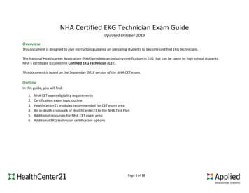
HOSHIZAKI MODEL NUMBERIDENTIFICATION CODEKM 1200 M A EUNIT TYPEKML KM FDCM DB BDM -Low Profile Crescent CuberCrescent CuberFlakerDispenser Cubelet MakerDispenser BinBinCountertop DispenserPRODUCTIONApproximate production/24 Hours@70 F Air/50 F WaterUNIT STYLEMSB-ModularStackableSelf contained with binCONDENSER STYLEAWR-Air cooledWater cooledRemote air cooledGENERATIONModel designation(E R-22 refrigerant unit / except F-250BAEand KM-2400SRB3)The model number, serial number, electricalspecifications and refrigerant data are found onthe unit name plate. (See name plate)511-01-02
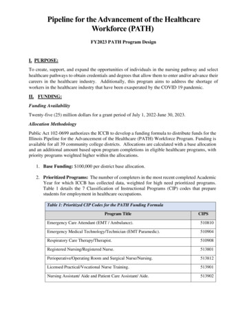
NAMEPLATEHOSHIZAKI ICE MAKERMODEL NUMBERSERIAL NUMBERAC SUPPLY VOLTAGECOMPRESSORFANMAXIMUM FUSE SIZEMAX. HACR BREAKER (USA ONLY)MAX. CIRC. BREAKER (CANADA ONLY)MINIMUM CIRCUIT AMPACITYDESIGN PRESSUREREFRIGERANTMOTOR-COMPRESSOR THERMALLY PROTECTEDHOSHIZAKI AMERICA, INC.Peachtree City, GALISTEDICE MAKERWITHOUTSTORAGE MEANS946ZNSF CCOMPONENTvSee the Nameplate for electrical and refrigeration specifications. This Nameplate is located on the upper right handside of rear panel. Since this Nameplate is located on therear panel of the icemaker, it cannot be read when the backof the icemaker is against a wall or against another piece ofkitchen equipment. Therefore, the necessary electrical andrefrigeration information is also on the rating label, whichcan be easily seen by removing only the front panel of theicemaker. We reserve the right to make changes in specifications and design without prior notice.611-01-02
WARRANTY INFORMATIONREGISTRATIONTwo warranty registration cards are supplied with theequipment. They must be completed and sent in to initiatewarranty. The warranty begins on the date of installation ifregistration procedures are followed. If registration is notcompleted, the warranty date will be the date of sale ordate of shipment from the factory, respectively.WARRANTY COVERAGEThe warranty will cover defects in material or workmanship under normal and proper use and maintenanceservice as specified by Hoshizaki. Coverage for parts andlabor is limited to the repair or replacement of parts orassemblies that in Hoshizaki's opinion are defective.COVERAGE CHARTITEMPRODUCTPARTSLABORTotal UnitKM CuberF/DCMB/DB/DMBev. Valves3 Years1 Year2 Years1 Year3 Years1 Year2 Years1 YearCompressor & AirCooled CondenserKM CuberF/DCM5 Years5 Years3 Years2 YearsEvaporator PlateKM Cuber5 Years5 YearsEvaporator, AugerGear Motor Assy.F/DCM2 Years2 YearsEffective January 1, 1991See Warranty Statement supplied with the unit for details.Warranty valid in United States, Canada, Mexico, PuertoRico, and U. S. Virgin Islands.Contact factory for warranty in other countries, territories,or possessions.711-01-02
KM INSTALLATIONGENERAL The ice machine is not intended for outdoor use.OPERATING CONDITIONS - ALL MODELSITEMVoltage RangeMODEL115V units208-230 V unitsRANGE104- 127V.187 - 264 V.Ambient TemperatureAll45 - 100 Deg. F.Remote Condenser -20 - 122 Deg. F.Water Supply Temperature All45 - 90 Deg. F.Water Supply Pressure10 -113 PSIGAllAllow 6" clearance at rear, sides, and top for proper aircirculation and ease of maintenance or service. 20" topclearance for F/DCM.PLUMBING REQUIREMENTS Water Supply:On KM units the water supply line size is critical due tothe water assisted harvest and the use of a ported inletwater valve solenoid. * Plumbing tubing size orequivilent.MODELKM-250 - KM-800KM-1200 - KM-2400All F/DCMLine Size3/8" *1/2" *3/8" *Fitting Size1/2 FPT1/2 FPT1/2 FPT*Water cooled condenser units require two separatesupplies sized as per list above.Drain:MODELLine SizeAll Bins3/4" IDAll KM's3/4" IDFlakers3/4" IDDCM3/4" ID*Some models have 2 drain outlets.8Fitting Size3/4 FPT3/4 FPT3/4 FPT*3/4 FPT*11-01-02
Hoshizaki recommends that the ice machine drain andbin drain be piped separately to the drain connection pointallowing 1/4" per foot fall.CONDENSATE DRAIN The condensate drain is generally connected to the icemachine drain for simplicity. It can be piped separately tothe drain exit if desired.A 6" vent tee is recommended as per drawing:CondensateDrainReservoirDrainFLOW RATES The minimum flow rate requirements for Hoshizaki icemaker units are as follows:KM-250/280/AII FlakersKM-500KM-630/800/AII PMGPMGPMGPMGPMUse this information when sizing a filter system for the icemachine application.NOTE: A good rule of thumb is to utilize a 3 GPM flowrate filter for KM-250 through 800 and a 5 GPM flow ratefilter for KM-1200 or larger.911-01-02
ELECTRICAL CONNECTIONS 115 VOLT/1 PHASE115V.(2 wirew/gnd)115V.NeutralBrownWhiteGND208-230 VOLT/1PHASE208-230V/1 Phase units require a dedicated neutral dueto the use of 115V components.115V.208-230V.Neutral(3 wire115V.w/gnd)BrownWhiteBlackGNDThe dedicatedneutralrequires aninsulatedconductorwhich runsdirectly to thepanel.If high leg is present connect to black wire.A transformer can be used to provide 115vcontrol circuit. See next page for details.208-230 VOLT/3 PHASE208-230V.3 phase(3 wirew/gnd)115V.115V.115V.BlackRedBrownGNDREMOTE CONDENSER alWhiteGND1011-01-02
Note:Electrical connections must be made in accordance withall national and local electrical codes.Transformer ApplicationAll 3 phase models include a 115V transformer with a 208/230V selector switch. Be sure to select the position thatbest matches the in-coming voltage prior to supplying powerto unit. (Voltage from the center tap to case ground willread 67.5V due to transformer circuit.)208-230V models include 115V controls. They require a115 / 208-230V circuit which has 4 wires including L1, L2,dedicated neutral, and gnd.If a dedicated neutral is not available or the previous unitused a 3 wire circuit (L1,L2, & gnd.), a step-down transformer can be used at the unit to provide power to the115V components. This will save on installation time andcost if a dedicated neutral is not present.Transformer # 4A0817-01 or equivalent can be used forKM models. Transformer # 446240-01 or equivalent canbe used for F-1000 models. This transformer should bemounted inside the compressor compartment and wiredusing the following generic diagram.GND.L1L2230V 208V L1BKNWL2BNUNIT1111-01-02
REMOTE APPLICATIONSCONDENSER CHARTCONDENSER MODELMODEL NUMBERSURC-6EURC-12EURC-20EKM-500/630MRE, F-1000MREKM-800/1200MRE, KM-1200SREKM-1600MRE, KM-1600/2000SRE,F-2000MREKM-2400SRBURC-24CWhen installing a remote application the unit/condensercombination must match with the above chart. A nonOEM multi-pass condenser can be used with prior writtenfactory approval.REMOTE LINESHoshizaki has 3 precharged line set lengths. 20 foot, 35foot, and 55 foot sets are available. The line sets areavailable in different line sizes for different models.LINE SET IDENTIFICATION CODER22-35610RefrigerantLength In FeetLiquid Line Size in 16th’sDischarge Line Size in 16th’sLINE SET APPLICATIONSMODELSKM-500/630, F-1000KM-800/1200KM-1600/2000/2400F-2000LINE SETR22- 46-2R22- 68-2R22- 610R22- 61012LL (SIZE) DL1/4" OD 3/8" OD3/8" OD 1/2" OD3/8" OD 5/8" OD3/8" OD 5/8" OD11-01-02
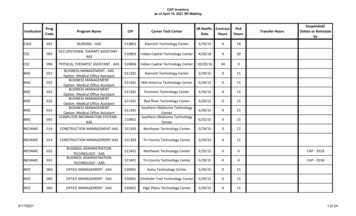
Remote Condenser Installation on RoofFor bestperformanceallow 24”clearance forair circulationFor best performance the RemoteCondenser shouldnot be more than33’ above theicemaker or morethen 10’ below it.These distancesare measured fromfitting to fitting.2½” Dia. Hole inroof for tubing Seal afterinstallation toprevent leakingAir FlowSecure Legsto Roof CurbLiquidLineDischargeLineElectrical connectionsmust meet all localcodesLiquidLineRemote CondenserFan MotorConnectionICEMAKERDischargeLineICE STORAGE BIN1311-01-02
LINE SET INSTALLATIONA universal line set adapter kit, part number OS-QUICK, isavailable if you need to field engineer your line set. Bothlines should be insulated separately the entire length ofrun.The refrigerant charge for a new unit is distributed between the unit head and the URC condenser. The line sethas a minimal holding charge of 15 to 30 psig refrigerantvapor.If you need to field engineer your line set or shorten/lengthen a precharged line set you can do so by followingthese steps:1. Using the OS-QUICK kit, braze the line set connections. (If you shorten or lengthen a precharged lineset, recover the holding charge, cut or lengthen andbraze the connections.)2. Pressurize the lines and leak check all braze joints.3. Evacuate the lines through the service ports on theAeroquip quick connect fittings.4. Charge both lines with 15 to 30 psig R-22 vapor.To make Aeroquip connection to the unit head and condenser:1. Lubricate the threads and O-ring with cleanrefrigerant oil.2. Tighten the female connector until it bottoms out.Note: Be sure to use a back up wrench when tighteningthese fittings.3. Then turn an additional 1/4 turn to assure a goodbrass to brass seal. Leak check the joints with soapbubbles or an electronic leak detector.1411-01-02
SYSTEM CHARGE - R-22The ice machine head and URC condenser are shippedwith enough refrigerant charge for up to 66 feet of line setlength. The maximum line set length is 100 equivalent feetfrom the head to the condenser.For applications longer than 66 ft. up to the maximum 100ft. Iength, additional refrigerant must be added. For unitsutilizing 1/4" L.L. and 3/8" D.L., the line size should beincreased to 3/8"L.L. and 1/2"D.L. for the entire length ofthe run. Add 21 ounces plus 1/2 oz. per foot over 66 feet.For units utilizing 3/8"L.L., add 1/2 oz. per foot over 66feet.NOTE:(1) Recommended line sizes are same as listed inthe line set application chart. (Page 7)(2) Older models utilize R-502 refrigerant or R-12refrigerant. Always check the unit nameplate forthe correct refrigerant type.(3) If refrigerant is added due to extended line setlength, mark the correct total charge on the unitnameplate for future reference.(4) When routing and installing remote lines, alwaysuse standard refrigerant piping practices.(5) Hoshizaki recommends eliminating any excessloops in a pre-charged line set application beforemaking the unit connections. This will eliminate oiltraps and possible crimps in the excess tubing.(6) A service loop should be included behind the unitas shown in the illustration on page 13 to allowthe unit to be moved away from the wall ifneeded.CRITICAL CHARGE AMOUNTThe total system charge is critical for proper operationaccording to Hoshizaki specification. Always weigh in theproper charge per the following charge chart. (Remoteunits show standard charge good for up to 66 feet.) Unitcharge information is also found on the unit Name Plate.FOR FACTORY SUPPORTCONTACT HOSHIZAKI TECHNICAL SUPPORT AT:1 -800-233-1940E-Mail techsupport@hoshizaki.com1511-01-02
HOSHIZAKI CUBERREFRIGERANT R-22 CHARGE CHARTMODELBAE/BWEMAEMWEMAEMWEKML-200 MAEMWEKML-400MAEMWEKM-500 MAEMWEMREKM-630 MAE 50/60MWE 50/60MREKM-800 MAEMWEMREKM-1200MAEMWEMREKM-1600MRE 1/3KM-1200SAE 50/60SWE 50/60SRE 50/60KM-1600SWE 1/3SRE1/3KM-2000 SRE3SWE3KM-2400 SRB3TOTAL CHARGE REFRIGERANTKM-250KM-250KM-250KM-28012 Oz.12 Oz.11 Oz.11 Oz.11Oz.1Lb.11Oz.1Lb. 5 Oz.15 Oz.1 Lb. 8 Oz.1 Lb.4 Lbs.1 Lb. 6 Oz.1 Lb. 2 Oz.4 Lbs. 2 Oz.2 Lbs. 7 Oz.1 Lb. 12 Oz.11 Lbs.3 Lbs. 10 Oz.2 Lbs.11 Lbs.14 Lbs. 6 Oz.3 Lbs. 8 Oz.2 Lbs.12 Lbs. 2 Oz.2 Lbs. 14 Oz.14Lbs. 5 Oz.16 Lbs. 9 Oz.3 Lbs. 7 Oz.26 Lbs. 8 ��““““““““““““““URC (Condenser charge is included in remote totalabove.)URC-6E2 Lbs. 2 Oz.“URC-12E4 Lbs. 7 Oz.“URC-20E7 Lbs. 11 Oz“URC-24B11 Lbs“NOTE: To convert to grams multiply oz. X 28.35.1611-01-02
HOSHIZAKI FLAKERS/DCM'SREFRIGERANT CHARGE REF-2000MWEMREDCM-240 BAEDCM-450 BAEBWEDCM-700 BAEBWETOTAL CHARGE REFRIGERANT8 Oz.*R-134A1 Lb.R-221 Lb.5 Oz.“10 Oz.“1 Lb.8 Oz.“14 Oz.“4 Lbs.3 Oz.“1Lb. 14 Oz.“14 Lbs. 13 Oz.“11.6 oz.“1 Lb. 1.4 Oz.“11.6/13.4 Oz. (see nameplate)“1 Lb.9 Oz.“13.4 Oz.“HEAT LOADThe heat of rejection information listed below by modelnumber should be used for sizing air conditioning equipment or for sizing a water cooled cooling tower application.TOTAL HEAT REJECTIONAIRWATER COOLEDMODELCOOLED (CONDENSER ONLY)KM-250B/M5450 BTU/h5250 BTU/hKM-280M/KML-200M 0B4200--DCM-450B90007750DCM-700B105009680Figures shown are at 90 F air temp. 70 F water temp.Allow for a pressure diffenential of 7 psi across the watercooled condenser.1711-01-02
COMPONENT TECHNICAL DATA KM Control Board Factory SettingThere are 8 dip switches on the Alpine control board utilized in R-22 units. The dip switches are factory set foroptimum operation. The switches can be adjusted to provide flexibility when the unit is operating in a bad waterlocation allowing more cleaning capability.DIP SWITCH SETTING 90301014001120PUMP OUTsecondsMIN DEFWTRVALVEPERIODIC5120 180101010150180120 180OFF OFFON OFF010111PUMP OUTFREQUENCYOPTIONAL600cycles1/11/271/5 1/10ALWAYS OFFSWITCHTEST8ALWAYS OFFSwitch Code1 ON 0 OffINSTRUCTIONS:1. TO IMPROVE BUILT-IN CLEANING Adjust switchesper this guide. Switches 1& 2 provide for longer flushat the end of harvest. Switches 5 & 6 provide maximum cleaning at every harvest cycle 1 / 1 setting.The 1 / 10 setting will pump-out less to conserve water(less cleaning).2. DO NOT ADJUST SWITCHES 3, 4, 7, & 8 FROMTHE FACTORY SETTINGS!3. DO NOT MAKE CONNECTION TO THE RED K-4TERMINAL!.4. The replacement board should be adjusted to thefactory settings unless local condition requiresalternate settings.1811-01-02
“E” Control Board Adjustment ChartThe new “E” control board is designed as aservice replacement for “C” and Alpine boards.Early “E” boards have 8 dip switches. The latest“E” boards have 10 dip switches.“E” BOARD DIP SWITCH SETTING GUIDEADJUSTMENTSDEFROSTCOMPLETIONTIMERDIP #1Switch Code 1 ON 0 OFF01200seconds60900111120 180PUMP OUT30101TIME4001120Length of pumpout Min, DefrostTime Inlet WaterValvePERIODICseconds101010seconds150180120 180status5OFF OFF ON OFF010111PUMP OUTFREQUENCY600cycles1/11/2OPTIONAL1/5 1/10ALWAYS OFFSWITCH7TEST8MAX. FREEZE9110010101075/50hz 7060/60hz5060ALWAYS OFFDefaultTIME(Improved Eboard only.)minutesNOTE:Switches 1 8 are same as Alpine control board.Switches 9 & 10 allow for adjustment of the maximumfreeze cycle timer. If unit originally has board with 10switches, adjust 9 & 10 to original setting. If original boardhas 8 switches adjust 9 & 10 to default setting OFF & OFF.1911-01-02
SETTING CHART FACTORY DIP SWITCH SETTINGSWITCH CODE: 1 ON 0 OFFMODEL :12345678KM-250BAE/BWE10100000KM-250A/KML-400A/W M-280W/KML-200A00011100KM-500M A/W/R E00001100KM-630M A/W/R E00001100KM-800M A/W/R E00101100KM-1200M A/W/R E00101100KM-1200S A/W/R E00111100KM-1600MRE00101100KM-1600S W/R E00111100KM-2000S W/R E00111100KM-2400SRB00100000In case of 10 dip switches, 9 & 10 should beadjusted OFF for all models listed above.The original Alpine board, #2U0127-01 was installed on allKM models produced prior to Feb. 98. Models producedafter Feb 98 will have either #2U0127-01or the new “E”control board #2A0836-01. Universal Alpine board#2U0139-01 can replace a “C” or Alpine board. It has ablack jumper between relay X3 & X4. This jumper makesthis board a “C” board. Leave the jumper if there is a whitewire in the 10 pin connector. This jumper must be cut for anAlpine application (no white wire on 10 pin connector).2011-01-02
NOTE:Service replacement boards after Feb. 98 are #2A083602 or sub #2A1410-02. This “E” board is designed to replace “C”, Alpine, or original (01) “E” boards. An applicationswitch is located between relay X3 & X4. Follow the instructions on the board label to set this switch. If the 10 pinconnector has a white wire, switch to “C” position. If not,switch to “ALP”.BE SURE TO FOLLOW THE INSTRUCTIONSSUPPLIED WITH THE BOARD.The “E” service replacement board is smaller than the “C”or Alpine board. It will mount in the same location on 4 ofthe 6 mounting studs. You must cut the wire ties and stretchthe wiring to install the connectors. Each connection ismarked and connects the same as the original board.If the black jumper is cut/not cut improperly”C” board) orthe application switch (“E” board) is in the wrong position,the inlet water valve will not energize correctly or the compressor will operate continually when the power switch isturned OFF.“E” Control Board Functions An instruction label explaining the “E” board features isincluded somewhere on the unit (usually under the toppanel or on the control box cover). A stick-on label is alsoincluded with the service replacement. If you are replacingan “E” board, place the new label over the original label asit contains instructions for the application switch. This willadvise anyone performing future service that the originalboard has been replaced and explain the application switchas outlined below.See the information on the label or the following for theboard features. The new diagnostic features are addedwhen this board replaces a “C” or Alpine board.2111-01-02
“E” Control Board Functions continued:The #2A1410-02 universal replacement board has an application switch between relays X3 & X4 that is not included on the original factory board supplied with the unit.This application switch allows this replacement board tobe used on older C and Alpine control board models. Theapplication switch has 2 positions (C & ALP). On R404A models, this switch must be in the ALP position. If theswitch is left in the C position, the compressor contactorwill energize as soon as power is supplied to the unitwhether the power switch is ON or OFF.There are 4 green LED’s which light in sequence throughout the unit operation. It is important to note that the greenLED’s are not numbered consecutively. LED1 is located atthe edge of the board beside the K-2 transformer connection. The numbering sequence from the outside edge of theboard is 1, 4, 3, and 2.The green LED’s are also used for a built-in output testwhich can be conducted to diagnose a bad board. Thelabel explains the output test procedure. The correct lighting sequence for the output test is as follows. When thecontrol switch is switched ON with the output test switchS-3 ON, you will observe the following:the Red control power LED will light after 3 seconds. Thisindicates that the control transformer has correct outputvoltage. After a 5 second delay, LED2 lights. 5 secondslater LED2 goes out and LED3 lights. 5 seconds later LED3goes out and LED4 lights. 5 seconds later LED4 goes outand LED1 lights. 5 seconds later LED1 goes out and LED4lights to begin the normal sequence of operation. If theLED’s follow this sequence, the board is OK. If any otherlighting sequence occurs, the board is bad.Once the correct sequence is determined, the output testswitch should be replaced in the OFF position.A copy of the “E” board label is included on the next page.Review the board label thoroughly to understand the “E”board functions.2211-01-02
ATTENTION !THIS UNIT HAS A CONTROL PRODUCTS IMPROVED “E” CONTROLBOARD INSTALLED. HOSHIZAKI PART NUMBER 2A1410-01.The improved “E” board includes LED lights and audible alarm safeties. Thered LED indicates proper control voltage and will remain on unless a controlvoltage problem occurs. At startup a 5 second delay occurs while the boardconducts an internal timer check. A short beep occurs when the powerswitch is turned “ON” or “OFF”.The green LED’s 1 4 represent the corresponding relays and energize andsequence 5 seconds from initial startup as follows:Sequence Step1 Minute Fill CycleHarvest CycleFreeze CycleReverse Pump OutLED’s on:Length:Min.Max.LED 4LED 1, 4, & 22 min.20 min.LED 15 min.60 min.LED 1, 3, & 210 sec.20 sec.Avg.60 sec.3-5 min.30-35 min.Factory set.{With light on, LED 1 Comp/RFM; LED 2 HGV; LED 3 PM; LED 4 WV}Note: LED’s are not numbered consecutively. They are # 1,4,3,2 from board edge.The built in safeties shut down the unit and have alarms as follows:1 beep every 3 sec. High Evaporator Temperature 127 F.Check for defrost problem (stuck HGV or relay), hot water enteringunit, stuck headmaster, or shorted thermistor.2 beeps every 3 sec. Defrost Back Up Timer. Defrost 20 minutes.Orange LED marked “H Timer” energizes. Check for openthermistor, HGV not opening, TXV leaking by, low charge, orinefficient compressor.3 beeps every 3 sec. Freeze Back Up Timer. Freeze Specified SettingYellow LED marked “F Timer” energizes. Check for F/S stuckclosed (up), WV leaking by, HGV leaking by, PM not pumping, TXVnot feeding properly, low charge, or inefficient comp. Dip switches 9& 10 allow for factory adjustment of this back up timer feature.Note: 2 & 3 beep alarms represent 2 consecutive occurrences.Additional alarms for mechanical bin switch:4 beeps every 3 sec. Short Circuit between the K4 connection on thecontrol board and the bin control. Check connections and replacewire harness if necessary.5 beeps every 3 sec. Open Circuit between the K4 connection on thecontrol board and the bin control. Check connections and replacewire harness if necessary.Note: Units with mechanical bin switch installed, dip switch No.7 must bein the “ON” position. If thermostatic control is used No. 7 must be “OFF”.To manually reset the above safeties, depress white alarm reset buttonwith the power supply “ON”.6 beeps every 3 sec. Low Voltage. Control voltage 92 Vac 5%.The red LED will de-energize if voltage protection operates.7 beeps every 3 sec. High Voltage. Control voltage 147 Vac 5%.The red LED will de-energize if voltage protection operates.Note: The voltage safety automatically resets when voltage is corrected.The Output Test switch “S3” provides a relay sequence test. With powerOFF, place S3 on and switch power to ICE. The correct lighting sequenceshould be none, 2, 3, 4, 1, & 4, in 5 second intervals, then normal sequence.Components will cycle during test. S3 should remain in the “OFF” position fornormal operation.The dip switches should be adjusted per the adjustment chart published in theTech Specs book. No. 8 must remain in the “OFF” position.2311-01-02
Manual Reset SafetiesThe Alpine control board has one manual reset safety. It isthe 127 F high evaporator temperature safety. There is noindication that the Alpine board is off on this safety. Youwill only notice that the unit will restart in the 1 minute fillcycle when the power switch is shut OFF and Back ON.This is the only way to reset this safety. If this occurscheck for a hot gas circuit or valve problem, a headmasterstuck in
The minimum flow rate requirements for Hoshizaki ice maker units are as follows: KM-250/280/AII Flakers 1.05 GPM KM-500 1.58 GPM KM-630/800/AII DCM's 2.11 GPM KM-1200/1600 3.96 GPM KM-2000/2400 4.23 GPM Use this information when sizing a filter system for the ice machine application.