Transcription
Service ManualCommercial SeriesRefrigerated Kitchen EquipmentModelsUpright S-Serieshoshizakiamerica.comNumber: 73207Issued: 8-3-2015Revised: 12-16-2019
WARNINGOnly qualified service technicians should install and service the appliance. Toobtain the name and phone number of your local Hoshizaki Certified ServiceRepresentative, visit www.hoshizaki.com. No service should be undertaken untilthe technician has thoroughly read this Service Manual. Failure to service andmaintain the appliance in accordance with this manual will adversely affect safety,performance, component life, and warranty coverage. Proper installation is theresponsibility of the installer. Product failure or property damage due to improperinstallation is not covered under warranty.Hoshizaki provides this manual primarily to assist qualified service technicians in theservice and maintenance of the appliance.Should the reader have any questions or concerns which have not been satisfactorilyaddressed, please call, send an e-mail message, or write to the Hoshizaki TechnicalSupport Department for assistance.Phone: 1-800-233-1940; (770) 487-2331Fax: 1-800-843-1056; (770) 487-3360E-mail: techsupport@hoshizaki.com618 Highway 74 SouthPeachtree City, GA 30269Attn: Hoshizaki Technical Support DepartmentWeb Site: www.hoshizaki.comNOTE: To expedite assistance, all correspondence/communication MUST include thefollowing information: Model Number Serial Number Complete and detailed explanation of the problem.2
IMPORTANTThis manual should be read carefully before the appliance is serviced. Readthe warnings and guidelines contained in this manual carefully as they provideessential information for the continued safe use, service, and maintenance of theappliance. Retain this manual for any further reference that may be necessary.CONTENTSImportant Safety Information. 5I. General Information. 8A. Construction. 8B. Refrigeration Flow Chart. 10II. Sequence of Operation and Service Diagnosis.11A. Sequence of Operation Flow Charts.111a. Refrigerator Auxiliary Code F-6 and Earlier.111b. Refrigerator: Auxiliary Code F-7 and Later. 122a. Freezer: Auxiliary Code F-7 and Earlier. 132b. Freezer: Auxiliary Code F-8 and Later. 14B. Service Diagnosis. 151a. Refrigerator: Auxiliary Code F-6 and Earlier. 161b. Refrigerator: Auxiliary Code F-7 and Later. 192a. Freezer: Auxiliary Code F-7 and Earlier. 222b. Freezer: Auxiliary Code F-8 and Later. 27C. Control Module Check. 32D. Thermistor Check. 34E. Diagnostic Tables. 34III. Controls and Adjustments. 37A. Control Module. 371. Display Icons . 372. Display Layout. 373. Control Module Connections. 38B. Temperature . 391. Default Settings. 392. Temperature Setpoint. 393. Changing the Temperature Display Scale ( F or C). 39C. Defrost. 40D. Alarm Safeties. 41E. Safety Devices. 42F. Mullion/Perimeter Heater. 42IV. Replacement of Components. 43A. Service for Refrigerant Lines. 43B. Important Notes for Component Replacement. 46C. Door Reversal. 46V. Maintenance. 47VI. Preparing the Appliance for Periods of Non-Use. 48VII. Disposal. 493
VIII. Technical Information. 50A. Electrical and Refrigerant Data. 50B. Wiring Diagrams. 511. CR1S-FS/FSL/HS/HSL Auxiliary Code E-5 and Earlier. 512. CR2S-FS/HS Auxiliary Code E-5 and Earlier. 523. HS Auxiliary Code E-6 to F-6. 534. CR1S-FGE/FGECL/FGECR/FS/FSL/HS/HSL,CR2S-FGE/FS/HS Auxiliary Code F-7 and Later. 545. CF1S-FS/FSL/HS/HSL Auxiliary Code E-5 and Earlier. 556. CF1S-FS/FSL/HS/HSL Auxiliary Code E-6 to F-7. 567. CF1S-FGE/FGECL/FGECR/FS/HS F-8 and Later. 578. CF2S-FS/HS Auxiliary Code E-5 and Earlier. 589. CF2S-FS/FSL/HS/HSL Auxiliary Code E-6 to F-7. 5910. CF2S-FGE/FGECL/FGECR/FS/FSL/HS/HSL Auxiliary Code F-8 and Later. 6011. CR3S-FS/HS Receptacle Box Connection. 614
Important Safety InformationThroughout this manual, notices appear to bring your attention to situations which couldresult in death, serious injury, or damage to the appliance or damage to property.WARNINGIndicates a hazardous situation which could result in death orserious injury.NOTICEIndicates a situation which could result in damage to theappliance or property.IMPORTANTIndicates important information about the use and care of theappliance.WARNINGThe appliance should be destined only to the use for which it has been expresslyconceived. Any other use should be considered improper and therefore dangerous.The manufacturer cannot be held responsible for injury or damage resulting fromimproper, incorrect, and unreasonable use. Failure to service and maintain theappliance in accordance with this manual will adversely affect safety, performance,component life, and warranty coverage.To reduce the risk of death, electric shock, serious injury, or fire, follow basicprecautions including the following: Only qualified service technicians should install and service the appliance. The appliance must be installed in accordance with applicable national, state, andlocal codes and regulations. The appliance requires an independent power supply of proper capacity. See thenameplate for electrical specifications. Failure to use an independent powersupply of proper capacity can result in a tripped breaker, blown fuse, or damageto existing wiring. This could lead to heat generation or fire. To reduce the risk of electric shock, do not touch the plug or power switch withdamp hands. Make sure the power switch is in the "OFF" position before plugging in orunplugging the appliance to reduce the risk of electric shock. Before servicing, move the power switch to the "OFF" position. Unplug theappliance from the electrical outlet.For 115VAC Models THE APPLIANCE MUST BE GROUNDED: The appliance is equipped with aNEMA 5-15 three‑prong grounding plugto reduce the risk of potential shockhazards. It must be plugged into a properly grounded, independent 3-prong walloutlet. If the outlet is a 2-prong outlet, it is your personal responsibility to have aqualified electrician replace it with a properly grounded, independent 3-prong walloutlet. Do not remove the ground prong from the plug and do not use an adapterplug. Failure to follow these instructions may result in death, electric shock, or fire.5
WARNING, continuedFor 208-230VAC Models THE APPLIANCE MUST BE GROUNDED: The appliance is equipped with aNEMA L14-20 four-prong locking, grounding plugto reduce the risk of potentialshock hazards. It must be plugged into a properly grounded, independent 4-prongwall outlet. If the outlet is a 3-prong outlet or a 4-prong non‑locking outlet, it is yourpersonal responsibility to have a qualified electrician replace it with a properlygrounded, independent 4-prong locking wall outlet. Do not remove the groundprong from the plug and do not use an adapter plug. After plugging in, twist the plugclockwise to lock it into place. Failure to follow these instructions may result in death,electric shock, or fire.For All Models The GREEN ground wire in the factory-installed power cord is connected to theappliance. If it becomes necessary to remove or replace the power cord, be sure toconnect the power cord's ground wire. Do not use an extension cord. Do not use an appliance with a damaged power cord. The power cord should notbe altered, jerked, bundled, weighed down, pinched, or tangled. Such actions couldresult in electric shock or fire. To unplug the appliance, be sure to pull the plug, notthe cord, and do not jerk the cord. Before unplugging a 4-prong plug, rotate the plugcounter-clockwise to unlock it. Do not splash, pour, or spray water directly onto or into the appliance. This mightcause short circuit, electric shock, corrosion, or failure. Do not make any alterations to the appliance. Alterations could result in electricshock, injury, fire, or damage to the appliance. The appliance is not intended for use by persons (including children) with reducedphysical, sensory, or mental capabilities, or lack of experience and knowledge,unless they have been given supervision or instruction concerning use of theappliance by a person responsible for their safety. Children should be properly supervised around the appliance. Do not climb, stand, or hang on the appliance or door or allow children or animals todo so. Do not climb into the appliance or allow children or animals to do so. Death orserious injury could occur or the appliance could be damaged. Be careful not to pinch fingers when opening and closing the door. Be careful whenopening and closing the door when children are in the area. Open and close the doors with care. Doors opened too quickly or forcefully maycause injury or damage to the appliance or surrounding equipment. Do not use combustible spray or place volatile or flammable substances near theappliance. They might catch fire. Keep the area around the appliance clean. Dirt, dust, or insects in the appliancecould cause harm to individuals or damage to the appliance. Do not throw anything onto the shelves or load any single shelf with more than120 lb. (54.5 kg) of product. They might fall off and cause injury.6
WARNING, continued Do not place anything on top of the appliance. Foreign objects or moisture couldenter the appliance and result in electric shock or fire. The appliance is designed only for temporary storage of food. Employ sanitarymethods. Use for any other purposes (for example, storage of chemicals or medicalsupplies such as vaccine and serum) could cause deterioration of stored items. Do not block air inlets or outlets, otherwise cooling performance may be reduced. Do not tightly pack the cabinet. Allow some space between items to ensure good airflow. Also allow space between items and interior surfaces. Do not put warm or hot foods in the cabinet. Let them cool first, or they will raise thecabinet temperature and could deteriorate other foods in the cabinet or overload theappliance. All foods should be wrapped in plastic film or stored in sealed containers. Otherwisefoods may dry up, pass their smells onto other foods, cause frost to develop, resultin poor appliance performance, or increase the likelihood of cross‑contamination.Certain dressings and food ingredients, if not stored in sealed containers, mayaccelerate corrosion of the evaporator, resulting in failure. Do not store items near the air outlet. They might freeze up and crack or breakcausing a risk of injury or contamination of other food.NOTICE Protect the floor when moving the appliance to prevent damage to the floor. Keep ventilation openings, in the appliance enclosure or in the built-in structure,clear of obstruction. Do not place anything on top of the appliance. Blockage ofairflow could negatively affect performance and damage the appliance. To prevent deformation or cracks, do not spray insecticide onto the plastic parts orlet them come into contact with oil. To avoid damage to the gasket, use only the door handle when opening and closing.7
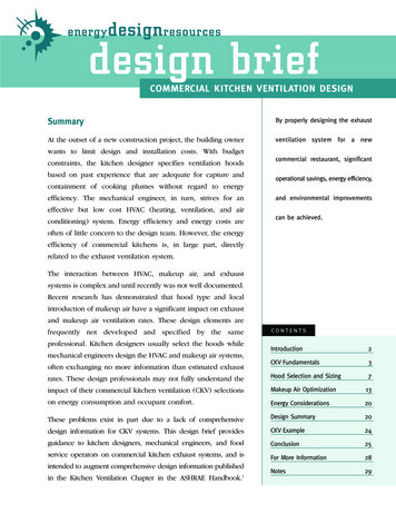
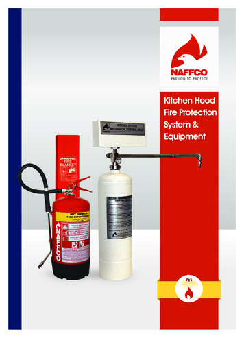
I. General InformationA. Construction1. Solid Door ModelsThermostatic Expansion ValvePower SwitchCondenser Fan MotorCompressorCondenserControl BoxFront PanelControl ModuleDoor LockPower CordDoorLightDoor SwitchDoorGasket Evaporator Cabinet Thermistor Defrost Thermistor Evaporator Fan ShroudCondensate Tube and SpringCondensate PanPressure Relief ValveModel Shown: CR1S-FS8
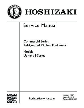
2. Glass Door ModelsThermostatic Expansion ValveCondenser Fan MotorCondenserCompressorControl BoxFront PanelDoor LockPower Cord24VDC DriverFGE GlassDoor ModelsPower SwitchControl ModuleLight Switch(glass doormodels only)LED LightsFGE GlassDoor ModelsDoor Evaporator Cabinet Thermistor Defrost Thermistor Evaporator Fan ShroudDoorGasketModel Shown: CR2S-FGEPressure ReliefValveCondensate Tubeand SpringCondensate PanFluorescent Light Assembly:FGY Glass Door ModelsFluorescent Light BallastFluorescentLight MountFluorescent LightBulbFluorescent LightBulb GuardModel Shown: CR2S-FGE9
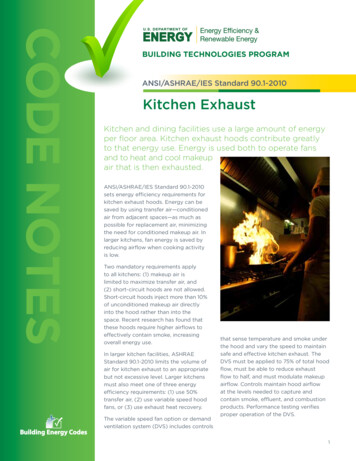
B. Refrigeration Flow ChartCondenserHigh-Pressure SwitchCondenser FanThermostaticExpansion ValveDrierCompressorEvaporator Fans(quantity depends on model)DefrostThermistorEvaporatorCabinet ThermistorDefrost Heater andDefrost Thermostat(freezer only)Condensate Pan10
11CTh in control2-min. Comp ontimer startsLegend:Comp-compressorConFM-condenser fan motorCTh-cabinet thermistorDTh-defrost thermistorEvapFM-evaporator fan motorEvapFM energizedComp de-energizedConFM de-energized20-min.minimumdefrost2-hr defrost timerterminates4. DefrostDTh in controla) EvapFM de-energizes when door is opened on -FS models andwhen upper door is opened on -HS models.b) 2-min. minimum Comp on timer starts when Comp energizes.c) 2-min. minimum Comp off timer starts when Comp de-energizes.d) 20-min. minimum defrost time.e) 1-hr. maximum defrost time.f) Temperature displayed during defrost.Note:EvapFM energizedComp de-energizedConFM de-energized2-min. Comp offtimer startsCTh coolsto 3 F (1.7 C)below setpoint.Factory default36 F (2 C)CTh warmsto 3 F (1.7 C)abovesetpoint2. Cool Down Achieved3. Cool Down Restart1. Startup/Cool DownEvapFM energized Comp energizedConFM energizedEvapFM energizedPower OnSlightDelay atStartupCycle StepsRefrigerator Auxiliary Code F-6 and Earlier Sequence Flow ChartComp energizedConFM energizedEvapFM energizedDTh warms to40 F (4.4 C) or1-hr maximumdefrost timerterminates5. Defrost TerminationII. Sequence of Operation and Service DiagnosisA. Sequence of Operation Flow Charts1a. Refrigerator Auxiliary Code F-6 and Earlier
Power on12Comp energizedConFM energizedEvapFM energized2-min. Comp ontimer starts2-hr defrost timerstartsEvapFM energizedComp de-energizedConFM de-energized20-min.minimumdefrost2-hr defrost timerterminates4. DefrostComp energizedConFM energizedEvapFM energizedDTh in controlDTh warms to44 F (6.6 C) or1-hr maximumdefrost timerterminates5. Defrost Terminationa) EvapFM de-energizes when door is opened on -FS models and when upper door is opened on -HS models.b) 2-min. minimum Comp on timer starts when Comp energizes.c) 2-min. minimum Comp off timer starts when Comp de-energizes.d) 20-min. minimum defrost time.e) 1-hr. maximum defrost time.f) Temperature displayed during defrost.Note:Comp de-energizedConFM de-energizedEvapFM de-energizedCTh in control2-min. Comp offtimer startsCTh cools to3 F (1.7 C)below setpoint.Factory default33 F (1 C)CTh warmsto 3 F (1.7 C)above setpoint2. Cool Down Achieved3. Cool Down Restart1. Startup/Cool DownLegend:Comp-compressorConFM-condenser fan motorCTh-cabinet thermistorDTh-defrost thermistorEvapFM-evaporator fan motorCycle StepsSlightDelay atStartupRefrigerator Auxiliary Code F-7 and Later Sequence Flow Chart1b. Refrigerator: Auxiliary Code F-7 and Later
13Comp energizedConFM energizedEvapFM energizedMH energizedPH energized2-min. Comp ontimer startsCTh cools to3 F (1.7 C)below setpoint.Factory default-4 F (-20 C)DTh in controlDH energizedDrH energizedMH energizedPH energizedComp de-energizedConFM de-energizedEvapFM de-energizedCTh warmsto 3 F (1.7 C)above setpointDTh warms to 59 F (15 C)5. Defrost TerminationMH energizedPH energizedDH de-energizedDrH de-energizedAfter Delay:Comp energizedConFM energizedEvapFM energized4-hr cumulative Comp runtime defrost timer terminates4. Defrosta) EvapFM de-energizes when door is opened on -FS models and when upper door is opened on -HS models.b) 2-min. minimum Comp on timer starts when Comp energizes.c) 2-min. minimum Comp off timer starts when Comp de-energizes.d) 5-min. minimum defrost time.e) 1-hr. maximum defrost time.f) 3-min. Comp/ConFM delay timer starts when defrost termination temperature is met.g) 7-minute EvapFM delay timer starts when defrost termination temperature is met (3-minute delay timer when defrost initiated manually)h) 18-minute temperature display delay timer starts when defrost termination temperature is met (15-minute delay timer when defrostinitiated manually).Note:EvapFM energizedMH energizedPH energizedComp de-energizedConFM de-energizedCTh in control2-min. Comp offtimer starts4-hr. cumulative Comp runtime defrost timer startsLegend:Comp-compressorConFM-condenser fan motorCTh-cabinet thermistorDH-defrost heaterDrH-drain heaterDTh-defrost thermistorEvapFM-evaporator fan motorMH-mullion heaterPH-perimeter heaterMH energizedPH energizedPower onSlightDelay atStartup2. Cool Down Achieved3. Cool Down Restart1. Startup/Cool DownFreezer Auxiliary Code F-7 and Earlier Sequence Flow Chart2a. Freezer: Auxiliary Code F-7 and Earlier
2-min. Comp ontimer starts14Legend:Comp-compressorConFM-condenser fan motorCTh-cabinet thermistorDH-defrost heaterDrH-drain heaterDTh-defrost thermistorEvapFM-evaporator fan motorMH-mullion heaterPH-perimeter heaterCTh cools to3 F (1.7 C)below setpoint.Factory default-4 F (-20 C)DTh in controlDH energizedDrH energizedComp de-energizedConFM de-energizedEvapFM de-energizedMH de-energizedPH de-energizedCTh warmsto 3 F (1.7 C)above setpoint5-hr. cumulative Comp runtime defrost timer terminates4. DefrostDH de-energizedDrH energizedAfter Delay:Comp energizedConFM energizedEvapFM energizedMH energizedPH energizedDTh warms to 45 F (7.2 C)5. Defrost Terminationa) EvapFM de-energizes when door is opened on -FS models and when upper door is opened on -HS models.b) 2-min. minimum Comp on timer starts when Comp energizes.c) 2-min. minimum Comp off timer starts when Comp de-energizes.d) 5-min. minimum defrost time.e) 1-hr. maximum defrost time.f) 3-min. Comp/ConFM/MH/PH delay timer starts when defrost termination temperature is met.g) 7-minute EvapFM delay timer starts when defrost termination temperature is met (3-minute delay timer when defrost initiated manually)h) 18-minute temperature display delay timer starts when defrost termination temperature is met (15-minute delay timer when defrostinitiated manually).Note:Comp de-energizedConFM de-energizedDrH energizedEvapFM de-energizedMH de-energizedPH de-energizedCTh in control2-min. Comp offtimer starts5-hr. cumulative Comp runtime defrost timer startsDrH energized Comp energizedConFM energizedDrH energizedEvapFM energizedMH energizedPH energizedPower onSlightDelay atStartup2. Cool Down Achieved3. Cool Down Restart1. Startup/Cool DownFreezer Auxiliary Code F-8 and Later Sequence Flow Chart2b. Freezer: Auxiliary Code F-8 and Later
B. Service DiagnosisWARNING The appliance should be diagnosed and repaired only by qualified servicepersonnel to reduce the risk of death, electric shock, serious injury, or fire. Risk of electric shock. Use extreme caution and exercise safe electrical practices. Moving parts (e.g., fan blade) can crush and cut. Keep hands clear. Make sure all food zones are clean after the appliance is serviced.NOTICE This appliance is not intended for outdoor use. Normal operating ambient temperature:– Refrigerators and Solid Door Freezers 45 F to 100 F (7.2 C to 38 C)– Glass Door Freezers 45 F to 80 F (7.2 C to 27 C)Operation of the appliance, for extended periods, outside of this normaltemperature range may affect appliance performance. The appliance must not be located next to ovens, grills, or other high heatproducing equipment. The appliance must not be located in a corrosive environment. Minimum Clearance:Side3" (8 cm)Top12" (31 cm)Rear1" (3 cm)The diagnostic procedure is a sequence check that allows you to diagnose the electricalsystem and components. Before proceeding, check for correct installation and propervoltage per nameplate. Always choose a neutral (W) to establish a good neutralconnection when checking high voltages. If the display is in alarm, see "III.D. AlarmSafeties."IMPORTANTThe maximum allowable voltage variation is 10 percent of the nameplate rating.115VAC is used as a reference voltage when checking voltage to components.Voltage may vary depending on power supply.1. Factory Default Settings:a) Temperature Setpoint:ModelRefrigeratorAuxiliary Code Temperature SetpointF-6 and Earlier36 F (2 C)F-7 and Later33 F (1 C)FreezerAll-4 F (-20 C)b) Temperature Display Scale: F.For further details, see "II.C. Control Module Check" or "III. Controls and Adjustments." There is a minimum 2-min. Comp on time and 2-min. Comp off time.15
1) Move the power switch to the "OFF" position.2) Unplug the appliance from the electrical outlet.3) Remove the control box cover.4) Plug the appliance back into the electrical outlet.5) Move the power switch to the "ON" position.6) Confirm 115VAC at the power switch. On 3-section models, also confirm proper supplyvoltage at the receptacle box (115VAC for refrigerator/208‑230VAC for freezer).1a. Refrigerator: Auxiliary Code F-6 and Earlier7) Startup/Cool Down–There is a slight delay, cabinet temperature appears on display.Comp, ConFM, EvapFM, and MH energize. 2-hr. defrost timer starts.a) EvapFM Diagnosis: Confirm EvapFM energizes. If not, confirm doors are closedand DS engaged. Next, check for 115VAC at DSR #8 (LBU or GY) to DSR #7 (W).If 115VAC is not present, check DS continuity. If DS is engaged and contacts areopen, replace DS. If 115VAC is present, check for 115VAC at DSR #4 (DBU) toneutral (W). If 115VAC is not present, check for 115VAC at DSR #6 (BK or W/BU) toneutral (W). If 115VAC is present at DSR #6 (BK or W/BU) to neutral (W) and not atDSR #4 (DBU) to neutral (W), replace DSR. If 115VAC is present at DSR #4 (DBU) toneutral (W), check EvapFM blades for binding and EvapFM continuity.b) Cabinet Light FGY (FGYCR and FGYCL) Diagnosis: Open the door and confirmCLS is in the ON position. If not, move CLS to the ON position. CLS turns on.If CLS does not turn on, check for 115VAC at both CLS (BK) wires to neutral (W).If 115VAC is present at one CLS (BK) wire and not at the other, confirm power supplyand continuity of CLS switch. If power supply is ok, check CLS continuity. If CLSis engaged and CLS switch is open, replace CLS. If CLS is engaged, contacts areclosed, and 115VAC is present at CLS (BK) and CL is not energized, replace CL.FS/HS CL Diagnosis: Open the door (upper on HS) and confirm CL is energized.If not, with the door open, check for 115VAC at DSR #5 (BK) to neutral (W) and DSR#1 (V or Y) to neutral (W). If 115VAC is not present at DSR #5 (BK), confirm powersupply and continuity of power switch. If 115VAC is present at DSR #5 (BK) and notpresent at DSR #1 (V or Y), check DS continuity. If DS is disengaged and contactsare closed (DSR energized), replace DS. If DSR is de‑energized and 115VAC ispresent at DSR #5 (BK) and not at DSR #1 (V or Y) to neutral (W), replace DSR.If 115VAC is present at DSR #1 (V or Y) and CL is not energized, replace CL.c) CM Diagnosis: Cabinet temperature appears on display. If not, check for 115VAC atCM 2 (L) (BK) to CM 3 (N) neutral (W). If 115VAC is not present, check power switch,power cord connections, and breaker/fuse. Confirm wiring connections are secure forboth CM 2 (L) (BK) (power supply) and CM 3( N) (W) (neutral). If 115VAC is presentand display is off, replace CM.16
d) Comp and ConFM Diagnosis: Confirm Comp and ConFM energize. If not, checkfor 115VAC at CM 1 (C) (R or V) to neutral (W). If 115VAC is not present, check CThstatus. See "II.D.Thermistor Check." If CTh ohm reading is in proper range, replaceCM. If 115VAC is present at CM 1 (C) (R or V) to neutral (W), check for 115VAC at CR#0 (GY or P) to CR #1 (W). If 115VAC is not present, check continuity of HPS.If open, allow time for HPS to reset (cut out: 300 10 PSIG, cut in: 190 20 PSIG).If HPS does not reset, see "e) HPS Activation" below. If HPS is closed and 115VAC ispresent, check for 115VAC at CR #4 (BK) and CR #6 (R) to neutral (W). If 115VAC ispresent at CR #4 (BK) and not at CR #6 (R), replace CR. If 115VAC is present at CR#6 (R) to neutral (W) and ConFM is energized but Comp is not, give time for Compinternal protector to cool and reset. Next, check Comp start capacitor, start relay,and Comp motor windings. If Comp does not start, replace Comp. If ConFM is notenergized, check ConFM fan blades for binding and motor winding continuity.If Comp and ConFM are energized and the cabinet does not cool down, check for arestriction in the refrigeration circuit, correct TXV operation, and correct refrigerantcharge.e) HPS Activation (cut out: 300 10 PSIG, cut in: 190 20 PSIG): Confirm ConFMis energized and fan blade turns freely. Confirm condenser coil is not clogged orrestricted. Confirm there are no restrictions in the refrigeration circuit (TXV and drier).Let refrigeration circuit pressures equalize. If HPS does not reset and pressuresare equalized, replace HPS. If pressures are not equalized, reclaim refrigerant anddiagnose refrigeration circuit restriction.8) Cool Down Achieved–CTh cools to 3 F (1.7 C) below setpoint. EvapFM continues.Comp and ConFM de‑energize. Diagnosis: Confirm Comp and ConFM de‑energize.If not, and Comp and ConFM were energized longer than 2 min., check CTh status.See "II.D. Thermistor Check." If CTh ohm reading is in range and Comp and ConFMcontinue longer than 2 min., check for 115VAC at CM 1 (C) (R or V) to neutral (W).If 115VAC is present, replace CM. If 115VAC is not present and Comp and ConFMcontinue, check for 115VAC at CR #6 (R) to neutral (W). If 115VAC is present, replaceCR.9) Defrost–Cabinet temperature is displayed during defrost. There is a 20-min. minimumdefrost time, a 1-hr. maximum defrost time, and a 2-hr. minimum defrost interval.1a) Time-Initiated: 2-hr. defrost timer terminates. EvapFM continues. Comp and ConFMde‑energize.1b) Manually-Initiated: To initiate a manual defrost, press the manual defrost buttonon display. Defrost icon turns on and, if energized, Comp and ConFM de‑energize.Cabinet temperature is displayed during defrost.2) Defrost Termination: DTh warms to 40 F (4.4 C). EvapFM and MH continue. Compand ConFM energize.17
Defrost Diagnosis:1a) Time-Initiation: 2-hr. defrost timer terminates.(1) CM Diagnosis: Conf
addressed, please call, send an e-mail message, or write to the Hoshizaki Technical Support Department for assistance. Phone: 1-800-233-1940; (770) 487-2331 Fax: 1-800-843-1056; (770) 487-3360 E-mail: techsupport@hoshizaki.com 618 Highway 74 South Peachtree City, GA 30269 Attn: Hoshizaki Technical Support Department Web Site: www.hoshizaki.com