Transcription
NETSCREEN-50User’s GuideVersion 5.0P/N 093-1249-000Rev. B
Copyright NoticeCopyright 2005 Juniper Networks, Inc. All rights reserved.Juniper Networks, the Juniper Networks logo, NetScreen, NetScreen Technologies, GigaScreen, and the NetScreen logoare registered trademarks of Juniper Networks, Inc. NetScreen-5GT, NetScreen-5XP, NetScreen-5XT, NetScreen-25,NetScreen-50, NetScreen-100, NetScreen-204, NetScreen-208, NetScreen-500, NetScreen-5200, NetScreen-5400,NetScreen-Global PRO, NetScreen-Global PRO Express, NetScreen-Remote Security Client, NetScreen-Remote VPNClient, NetScreen-IDP 10, NetScreen-IDP 100, NetScreen-IDP 500, GigaScreen ASIC, GigaScreen-II ASIC, andNetScreen ScreenOS are trademarks of Juniper Networks, Inc. All other trademarks and registered trademarks are theproperty of their respective companies.Information in this document is subject to change without notice.No part of this document may be reproduced or transmitted in any form or by any means, electronic or mechanical, for anypurpose, without receiving written permission from:Juniper Networks, Inc.ATTN: General Counsel1194 N. Mathilda Ave.Sunnyvale, CA 94089-1206FCC StatementThe following information is for FCC compliance of Class A devices: This equipment has been tested and found to complywith the limits for a Class A digital device, pursuant to part 15 of the FCC rules. These limits are designed to providereasonable protection against harmful interference when the equipment is operated in a commercial environment. Theequipment generates, uses, and can radiate radio-frequency energy and, if not installed and used in accordance with theinstruction manual, may cause harmful interference to radio communications. Operation of this equipment in aresidential area is likely to cause harmful interference, in which case users will be required to correct the interference attheir own expense.The following information is for FCC compliance of Class B devices: The equipment described in this manual generatesand may radiate radio-frequency energy. If it is not installed in accordance with NetScreen’s installation instructions, itmay cause interference with radio and television reception. This equipment has been tested and found to comply with thelimits for a Class B digital device in accordance with the specifications in part 15 of the FCC rules. These specifications aredesigned to provide reasonable protection against such interference in a residential installation. However, there is noguarantee that interference will not occur in a particular installation.If this equipment does cause harmful interference to radio or television reception, which can be determined by turning theequipment off and on, the user is encouraged to try to correct the interference by one or more of the following measures: Reorient or relocate the receiving antenna. Increase the separation between the equipment and receiver. Consult the dealer or an experienced radio/TV technician for help. Connect the equipment to an outlet on a circuit different from that to which the receiver is connected.Caution: Changes or modifications to this product could void the user's warranty and authority to operate this device.DisclaimerTHE SOFTWARE LICENSE AND LIMITED WARRANTY FOR THE ACCOMPANYING PRODUCT ARE SET FORTHIN THE INFORMATION PACKET THAT SHIPPED WITH THE PRODUCT AND ARE INCORPORATED HEREIN BYTHIS REFERENCE. IF YOU ARE UNABLE TO LOCATE THE SOFTWARE LICENSE OR LIMITED WARRANTY,CONTACT YOUR JUNIPER NETWORKS REPRESENTATIVE FOR A COPY.
ContentsPreface . vGuide Organization .vCommand Line Interface (CLI) Conventions . viJuniper Networks NetScreen Publications . viChapter 1 Overview . 1The Front Panel . 2Power and Status LEDs . 2Asset Recovery Pinhole. 4Console and Modem Ports. 4Compact Flash Card Slot . 4Ethernet Interfaces. 5The Rear Panel . 5Chapter 2 Installing the Device . 7General Installation Guidelines . 8Equipment Rack Mounting . 8Equipment Rack Installation Guidelines . 8Equipment Rack Accessories and Required Tools . 9NetScreen-50 Rack Mount . 9Chapter 3 Configuring the Device . 11Operational Modes . 12Transparent Mode . 12Route Mode. 12The NetScreen-50 Interfaces . 13Connecting the Device to a Network . 14Establishing an HA Connection Between Devices . 15Performing Initial Configuration Using the CLI . 17Connecting Using a vt100 Terminal Emulator.Setting an IP Address for Managing the Device .Connecting Using Telnet.Allowing Outbound Traffic .Changing Your Admin Name and Password .1718181919Accessing the Device With the WebUI . 20Asset Recovery . 20Using CLI Commands to Reset the Device . 21Using the Asset Recovery Pinhole to Reset the Device . 22Chapter 4 Replacing the Fuse . 23Appendix A Specifications. A-INetScreen-50 Attributes .A-IINetScreen-50iii
ContentsElectrical Specification . A-IIEnvironmental . A-IISafety Certifications . A-IIEMI Certifications . A-IIConnectors . A-IIIIndex.1-1ivUser’s Guide
PrefaceThe Juniper Networks NetScreen-50 device provides security for small and medium-sizedcompanies, as well as enterprise branch and remote offices. The NetScreen-50 deviceoffers 170 Mbps of firewall and 50 Mbps of 3DES VPN, protecting your LANs as well aspublic servers, such as mail, web, or FTP.GUIDE ORGANIZATIONThis manual has four chapters and one appendix.Chapter 1, "Overview" provides an overview of the system, its ports, and powerrequirements.Chapter 2, "Installing the Device" details how to install the NetScreen-50 device on adesktop or in a rack.Chapter 3, "Configuring the Device" details how to connect the NetScreen-50 device toyour network, establish a Console session, set an IP address for the NetScreen-50 device,and access the device using the WebUI.Chapter 4, "Replacing the Fuse" provides procedures on how to replace components on thedevice.Appendix A, "Specifications" provides a list of physical specifications about theNetScreen-50 device.NetScreen-50v
PrefaceCOMMAND LINE INTERFACE (CLI) CONVENTIONSThe following conventions are used when presenting the syntax of a command lineinterface (CLI) command: Anything inside square brackets [ ] is optional. Anything inside braces { } is required. If there is more than one choice, each choice is separated by a pipe ( ). Forexample,set interface { ethernet1 ethernet2 ethernet3 }managemeans “set the management options for the ethernet1, ethernet2, or ethernet3interface”. Variables appear in italic. For example:set admin user name1 password xyzWhen a CLI command appears within the context of a sentence, it is in bold (except forvariables, which are always in italic). For example: “Use the get system command todisplay the serial number of a NetScreen device.”Note: When typing a keyword, you only have to type enough letters to identify the worduniquely. For example, typing set adm u joe j12fmt54 is enough to enter the commandset admin user joe j12fmt54. Although you can use this shortcut when enteringcommands, all the commands documented here are presented in their entirety.JUNIPER NETWORKS NETSCREEN PUBLICATIONSTo obtain technical documentation for any Juniper Networks NetScreen product, visitwww.juniper.net/techpubs/.For technical support, open a support case using the Case Manager link at http://www.juniper.net/support/ or call 1-888-314-JTAC (within the United States) or 1-408-7459500 (outside the United States).If you find any errors or omissions in the following content, please contact us at the e-mailaddress below:techpubs-comments@juniper.netviUser’s Guide
1Chapter 1OverviewThis chapter provides detailed descriptions of the NetScreen-50 chassis.Topics explained in this chapter include: “The Front Panel” on page 2–“Power and Status LEDs” on page 2–“Asset Recovery Pinhole” on page 4–“Console and Modem Ports” on page 4–“Compact Flash Card Slot” on page 4–“Ethernet Interfaces” on page 5“The Rear Panel” on page 5Note: For safety warnings and instructions, please refer to the NetScreen Safety Guide.The instructions in this guide warn you about situations that could cause bodily injury.Before working on any equipment, be aware of the hazards involved with electricalcircuitry and be familiar with standard practices for preventing accidents.NetScreen-501
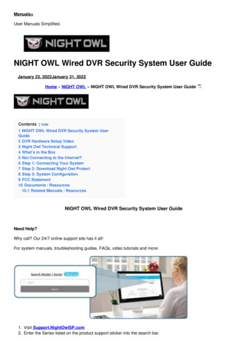
Chapter 1 OverviewTHE FRONT PANELThe front panel of the NetScreen-50 device has the following: Power and status LEDs. Asset Recovery pinhole, for resetting the device to the original factory defaultsettings. A Console port, for connecting to serial terminal emulation programs such asHyperTerminal. A modem port. A Compact Flash card slot, for storage of system images, configuration files,keys, and logs. Four Ethernet ports, for connecting the NetScreen-50 device to your LAN orlocal workstations and to the Internet.Power and Status LEDsAsset Recovery PinholeConsoleCompact Flash SlotEthernet PortsModemPower and Status LEDsThe LEDs display up-to-date information about critical NetScreen-50 functions.Status LEDHA LEDFlash LEDPower LEDAlarm LEDSession LED2User’s Guide
The Front PanelThe information revealed by each LED is as follows:LEDPurposeColorMeaningPowerPower StatusgreenPower is functioning correctly.offThe device is not receiving power.redCritical alarm—failure of hardware component orsoftware module (such as a cryptographicalgorithm)amberMajor alarm:Low memory ( 10% remaining)High CPU utilization ( 90%)Log memory fullSessions fullMaximum number of VPN tunnels reachedFirewall attacks detectedoffNo alarms.blinking greenNormal operation.greenBooting up normally.offNo HA activity has been defined.greenPort is a master in a redundancy cluster.amberPort is a slave in a redundancy cluster.amberSession utilization is between 70% and 90%.redSession utilization is greater than 90%.offNormal operation.AlarmStatusHASessionFlashSystem AlarmSystem StatusHigh Availability(HA)SessionUtilizationCompact Flashgreen(CF) Card Statusblinking greenoffNetScreen-50The card is installed.Read-write activity is detected.CF slot is empty.3
Chapter 1 OverviewAsset Recovery PinholeThe asset recovery pinhole is a switch that resets the device to its original defaultsettings. To use this switch, insert a stiff wire (such as a straightened paper clip) into thepinhole.Warning: Because resetting the device restores it to the original default configuration, anynew configuration settings are lost, and the firewall and all VPN service becomeinoperative.Console and Modem PortsThe Console port is a RJ-45 serial console port connector, for vt100 terminal emulatorprograms to perform local configuration and administration.The Modem port is a RJ-45 serial console port connector, for establishing remote consolesessions using dialup connections through a 9600 bps RS-232 cable. Dialing into themodem establishes the dialup console connection.The table below lists the RJ-45 to DB-9 adapter connection definitions. To employ astandard UART port, both the console and the modem ports must use this configuration.DB9SignalAbbreviation DTEDCERJ451Data Carrier DetectDCDInOutNC2Received DataRDInOut33Transmitted DataTDOutIn64Data Terminal ReadyDTROutIn75Signal GroundSGNDN/AN/A46Data Set ReadyDSRInOut27Request To SendRTSOutIn88Clear To SendCTSInOut19Ring IndicatorRIInOutNCCompact Flash Card SlotThe Compact Flash slot is for downloading or uploading system software orconfigurations. This slot can accept a SanDisk CompactFlashTM card with a variety ofmemory capacities. NetScreen has tested 96MB and 512MB cards. The NetScreen deviceautomatically detects the presence of a flash card and records the system log to it.4User’s Guide
The Rear PanelEthernet InterfacesEach Ethernet port is a 10/100 auto-sensing interface. Each port has a pair of LEDs: theleft LED indicates network traffic activity and the right LED indicates if the link is up(the port is connected to an active device).THE REAR PANELThe rear panel of the NetScreen-50 device contains the power outlet and ON/OFF switch.Power OutletON/OFF SwitchYou can order the NetScreen-50 device with either an AC or DC power supply.NetScreen-505
Chapter 1 Overview6User’s Guide
2Chapter 2Installing the DeviceThis chapter describes how to install a NetScreen-50 device in an equipment rack or on adesktop.Topics in this chapter include: “General Installation Guidelines” on page 8 “Equipment Rack Mounting” on page 8–“Equipment Rack Installation Guidelines” on page 8–“Equipment Rack Accessories and Required Tools” on page 9–“NetScreen-50 Rack Mount” on page 9Note: For safety warnings and instructions, please refer to the NetScreen Safety Guide.The instructions in this guide warn you about situations that could cause bodily injury.Before working on any equipment, be aware of the hazards involved with electricalcircuitry and be familiar with standard practices for preventing accidents.NetScreen-507
Chapter 2 Installing the DeviceGENERAL INSTALLATION GUIDELINESObserving the following precautions can prevent injuries, equipment failures andshutdowns. Never assume that the device is disconnected from a power source. Always checkfirst. Room temperature might not be sufficient to keep equipment at acceptabletemperatures without an additional circulation system. Ensure that the room inwhich you operate the device has adequate air circulation. Do not work alone if potentially hazardous conditions exist. Look carefully for possible hazards in your work area, such as moist floors,ungrounded power extension cables, frayed power cords, and missing safetygrounds. The product should be installed in a restricted area to prevent personal injuryfrom exposure to DC voltage.Warning: To prevent abuse and intrusion by unauthorized personnel, install theNetScreen-50 device in a locked-room environment.EQUIPMENT RACK MOUNTINGThe NetScreen-50 device comes with accessories for mounting the device in a standard19–inch equipment rack.Equipment Rack Installation GuidelinesThe location of the chassis, the layout of the equipment rack, and the security of yourwiring room are crucial for proper system operation.Use the following guidelines while configuring your equipment rack.8 Enclosed racks must have adequate ventilation. Such ventilation requireslouvered sides and a fan to provide cooling air. When mounting a chassis in an open rack, be sure that the rack frame does notblock the intake or exhaust ports. If you install the chassis on slides, check theposition of the chassis when it is seated all the way into the rack. In an enclosed rack with a ventilation fan in the top, equipment higher in therack can draw heat from the lower devices. Always provide adequate ventilationfor equipment at the bottom of the rack. Baffles can isolate exhaust air from intake air. The best placement of the bafflesdepends on the airflow patterns in the rack.User’s Guide
Equipment Rack MountingEquipment Rack Accessories and Required ToolsRack mounting requires the following accessories and tools: 1 Phillips-head screwdriver (not provided) 4 screws to match the rack (if the thread size of the screws provided in theNetScreen-50 product package do not fit the thread size of the rack) The included rack mount bracket kit.NetScreen-50 Rack MountTo rack mount the NetScreen-50 device:1.Screw the rack mount brackets to each side of the chassis.2.Screw the left and right brackets to the rack, as shown below.NetScreen-509
Chapter 2 Installing the Device10User’s Guide
3Chapter 3Configuring the DeviceThis chapter describes how to connect a NetScreen-50 device to your network and performinitial configuration on the device. Topics in this chapter include: “Operational Modes” on page 12–“Transparent Mode” on page 12–“Route Mode” on page 12 “The NetScreen-50 Interfaces” on page 13 “Connecting the Device to a Network” on page 14 “Establishing an HA Connection Between Devices” on page 15 “Performing Initial Configuration Using the CLI” on page 17–“Connecting Using a vt100 Terminal Emulator” on page 17–“Setting an IP Address for Managing the Device” on page 18–“Connecting Using Telnet” on page 18–“Allowing Outbound Traffic” on page 19–“Changing Your Admin Name and Password” on page 19 “Accessing the Device With the WebUI” on page 20 “Asset Recovery” on page 20–“Using CLI Commands to Reset the Device” on page 21–“Using the Asset Recovery Pinhole to Reset the Device” on page 22Note: For safety warnings and instructions, please refer to the NetScreen Safety Guide.The instructions in this guide warn you about situations that could cause bodily injury.Before working on any equipment, be aware of the hazards involved with electricalcircuitry and be familiar with standard practices for preventing accidents.Note: You must register your product at www.juniper.net/support/ so that certain ScreenOSservices, such as the Deep Inspection Signature Service, can be activated on the device.After registering your product, use the WebUI or CLI to obtain the subscription for theservice. For more information about registering your product and obtaining subscriptionsfor specific services, see the “System Parameters” chapter in Volume 2 of the NetScreenConcepts & Examples ScreenOS Reference Guide.Note: If you access the device for the first time using the ScreenOS WebUI graphicalinterface, the Initial Configuration Wizard appears when you log in to the WebUI. ThisWizard guides you through the configuration described in this chapter. For moreinformation about starting the Initial Configuration Wizard, refer to the Juniper NetworksNetScreen-50 Getting Started Guide.NetScreen-5011
Chapter 3 Configuring the DeviceOPERATIONAL MODESThe NetScreen-50 device supports two operational modes: Transparent and Route mode.The default mode is Route.Transparent ModeIn Transparent mode, the NetScreen-50 device operates as a Layer-2 bridge. Because thedevice cannot translate the IP addresses of packets, it cannot perform Network AddressTranslation (NAT). Consequently, for the device to access the Internet, any IP address inyour trusted (local) networks must be routable and accessible from untrusted (external)networks.In Transparent mode, the IP addresses for Trust and Untrust zones are 0.0.0.0, thusmaking the NetScreen device invisible to the network. However, the device can stillperform firewall, VPN, and traffic management according to configured security policies.Route ModeIn Route mode, the NetScreen-50 device operates at Layer 3. Because you can configureeach interface using an IP address and subnet mask, you can configure individualinterfaces to perform NAT. When the interface performs NAT services, the device translates the source IPaddress of each outgoing packet into the IP address of the untrusted port. It alsoreplaces the source port number with a randomly-generated value. When the interface does not perform NAT services, the source IP address andport number in each packet header remain unchanged. Therefore, to reach theInternet your local hosts must have routable IP addresses.For more information on NAT, see the NetScreen Concepts & Examples ScreenOSReference Guide.Important: Performing the setup instructions below configures your device in Routemode. To configure your device in Transparent mode, see the NetScreen Concepts &Examples ScreenOS Reference Guide.12User’s Guide
The NetScreen-50 InterfacesTHE NETSCREEN-50 INTERFACESEach NetScreen-50 device provides Ethernet interfaces for access and connectivity. Inaddition, there are logical (non-physical) interfaces that perform special Layer-2 ormanagement functions.The configurable interfaces available on a NetScreen-50 device are as follows:Interface TypeEthernet interfacesDescriptionethernetn specifies a physical ethernet interface, denoted by a physical port(n) on the module. Although each interface is bound to a security zone bydefault, you can bind it to another zone as required. ethernet1 Bound to the Trust zone by default. Connect this interface usinga twisted pair cable with RJ-45 connectors. ethernet2 Bound to the DMZ zone by default. Connect this interface usinga twisted pair cable with RJ-45 connectors. ethernet3 Bound to the Untrust zone by default. Connect this interfaceusing a twisted pair cable with RJ-45 connectors. ethernet4 Bound to HA zone by default.Layer-2 interfacesvlan1 specifies a logical interface used for management and VPN traffictermination while the NetScreen device is in Transparent mode.Tunnel interfacestunnel.n specifies a logical tunnel interface. This interface is for VPN traffic.NetScreen-5013
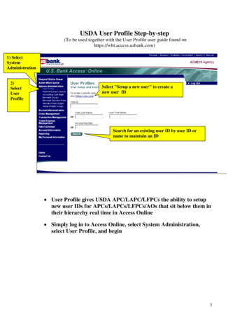
Chapter 3 Configuring the DeviceCONNECTING THE DEVICE TO A NETWORKThe following illustration shows typical cabling for 10/100 Base-T networks. This exampleuses the default interface bindings for the Ethernet ports.InternetRouterEthernet Port 3Ethernet Port 1To add a NetScreen-50 device to your network:1.(Optional) Install the NetScreen-50 device in an equipment rack (see“Equipment Rack Mounting” on page 8).2.Make sure that the power switch on the device is turned OFF.3.Connect the power cable, included in the product package, to the NetScreen-50power outlet at the rear of the device and to a power source.Warning: To prevent personal injury from exposure to DC voltage, alwaysreplace the insulating cap after installing power cables.4.Connect an RJ-45 cross-over cable from the Trust zone interface(Ethernet port 1) to the internal switch, router, or hub.Note: Check your router, hub, switch, or PC documentation to see if these devicesrequire any further configuration. In addition, see if it is necessary to switch OFFthe power to any new device you add to the LAN.5.14Connect an RJ-45 straight-through cable from the Untrust zone interface(Ethernet port 3) to the external router.User’s Guide
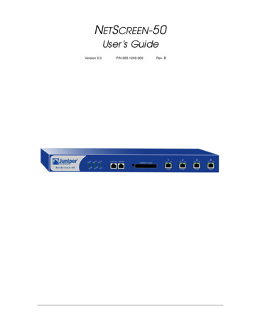
Establishing an HA Connection Between Devices6.Flip the power switch to the ON position.7.After the NetScreen-50 device starts, check the following LEDs:–The Power LED glows green.–The Status LED blinks green.–The Ethernet port LEDs for each connected interface glows or blinksgreen. (For more details about interpreting the Link Status LEDs, see“Ethernet Interfaces” on page 5.)ESTABLISHING AN HA CONNECTION BETWEEN DEVICESTo assure continuous traffic flow in the event of system failure, you can cable andconfigure two NetScreen devices in a redundant cluster. The devices propagate allnetwork, configuration and session information to each other. Should one device fail, theother takes over the traffic processing.The following diagram shows a typical HA setup for NetScreen-50 devices.InternetRoutersSwitch 1Switch 2To Untrust interfaceTo Untrust interfaceDevice 1Device 2To HA1 to HA2 interfacesTo TrustinterfaceTo TrustinterfaceSwitch 3NetScreen-50LANSwitch 415
Chapter 3 Configuring the DeviceTo cable two NetScreen-50 devices together for HA and connect them to the network:Note: The cabling instructions given below reproduce the configuration shown previously.However, this is not the only possible HA configuration. In addition, the instructionsassume that all physical ports and interfaces are still set at their default settings. If youhave changed the port and interface configurations, the instructions below might not workproperly.1.(Optional) Install the NetScreen-50 devices in an equipment rack (see“Equipment Rack Mounting” on page 8).2.Make sure that all ON/OFF power supply switches are OFF.3.Connect the power cables on each NetScreen-50 to a power source.Note: Whenever you deploy two NetScreen-50 devices in an HA cluster, connecteach to a different power source, if possible. If one power source fails, the othersource might still be operative.4.Connect a 10/100 Base-T cable from the HA1 zone interface (Ethernet port 4) onDevice 1 to the HA2 zone interface (Ethernet port 4) on Device 2.Device 15.On Device 1, connect a crossover cable from the Trust zone interface (Ethernetport 1) to the switch labeled “Switch 3.”6.On Device 1, connect a straight-through cable from the Untrust zone interface(Ethernet port 3) to the switch labeled “Layer 3 switch 1.”Device 27.On Device 2, connect a crossover cable from the Trust zone interface (Ethernetport 1) to the switch labeled “Switch 4.”8.On Device 2, connect a straight-through cable from the Untrust zone interface(Ethernet port 3) to the switch labeled “Layer 3 switch 2.”Switches9.Cable together the switches labeled “Switch 3” and “Switch 4.”10.Cable together the switches labeled “Layer 3 switch 1” and “Layer 3 switch 2.”11.Cable the switches labeled “Layer 3 switch 1” and “Layer 3 switch 2” to routers.Note: The switch ports must be defined as 802.1Q trunk ports, and the externalrouters must be able to use either Hot Standby Router Protocol (HSRP) or VirtualRouter Redundancy Protocol (VRRP). For the best configuration method, see thedocumentation for your switch or router.12.Turn the power switches for all devices ON.For more advanced HA configurations, see the NetScreen Concepts & Examples ScreenOSReference Guide.16User’s Guide
Performing Initial Configuration Using the CLIPERFORMING INITIAL CONFIGURATION USING THE CLIThere are two ways to establish a console session with the NetScreen-50 device: Using a vt100 terminal emulator, such as Hilgraeve Hyperterminal , throughan RJ-45 serial cable connected to the console port. Using Telnet through a TCP/IP network connection to the NetScreen-50 device.Connecting Using a vt100 Terminal EmulatorTo establish a connection to the NetScreen-50 device using a vt100 Terminal Emulator:1.Connect an RJ-45 serial cable between the console port on the NetScreen-50device and the serial port on your PC.2.Start the vt100 terminal emulator program on your PC.Typical settings for a console session are as follows: Baud Rate to 9600 Parity to No Data Bits to 8 Stop Bit to 1 Flow Control to none3.Press the ENTER key to see the login prompt.4.At the login prompt, type netscreen.5.At the password prompt, type netscreen.Note: Use lowercase letters only. Both login and password are case-sensitive.6.(Optional) By default, the console times out and terminates automatically after10 minutes of idle time. To change the timeout value, execute the followingcommand:set console timeout numberwhere number is the length of idle time, in minutes, before session termination.To prevent automatic termination, specify a value of zero.NetScreen-5017
Chapter 3 Configuring the DeviceSetting an IP Address for Managing the DeviceThe default IP address for managing the NetScreen-50 device through the Trust zoneinterface (Ethernet port 1) is 192.68.1.1. This is the IP address that you use to manage thedevice through a Telnet session or with the WebUI management application. If you do notwish to use this default IP address, you need to assign a new one.To set the IP address of the NetScreen-50 Trust zone interface:1.Choose an unused IP address within the current addre
DB9 Signal Abbreviation DTE DCE RJ45 1 Data Carrier Detect DCD In Out NC 2 Received Data RD In Out 3 3 Transmitted Data TD Out In 6 4 Data Terminal Ready DTR Out In 7 5 Signal Ground SGND N/A N/A 4 6 Data Set Ready DSR In Out 2 7 Request To Send RTS Out In 8 8 Clear To Send CTS In Out 1 9 Ring Indicator RI In Out NC