Transcription
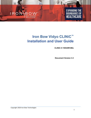
Iron Bow Vidyo CLINiC for ObservationInstallation and User GuideFor use with Iron Bow Part Number:CLINiC-VC-10X24IR-B03Document Part # DOC-UG-CLINIC-VC10X24-B03Version 5.003/15/20211Copyright 2021 Iron Bow Technologies
Copyright 2021 Iron Bow TechnologiesAll Rights Reserved.Specifications subject to change without notice.For general inquiries, contact:Iron Bow Healthcare Solutions2303 Dulles Station Boulevard, Suite 400Herndon, VA 20171Toll: 800.338.8866Tel: 703.279.3000www.ironbowhealthcare.comFor support, contact:Iron Bow Client Service CenterToll: 833.476.6269 (833.IRONBOW)Email: CSC@ironbow.com2Copyright 2021 Iron Bow Technologies
Safety & MaintenanceFor your protection, please read these safety instructions completely before operating the equipment and keep this manual forfuture reference. The information in this summary is intended for persons who operate the equipment as well as repair orservicing personnel. Carefully observe all warnings, precautions and instructions on the apparatus, or the ones described in theoperating instructions and adhere to them. Also, adhere to safety guidelines found in manuals for any peripheral equipment.Care and Handling Water and moisture - Do not operate the equipment under or near water, or in areas with high humidity. Cleaning - Unplug the apparatus from the wall outlet before cleaning. Do not use liquid cleaners or aerosol cleaners, followcleaning instructions provided Ventilation - Do not block any of the ventilation openings of the apparatus. Install in accordance with the installationinstructions. Grounding or Polarization – use the power cord provided with this system, do not defeat the safety purpose of thegrounding-type plug. A grounding type plug has two blades and a third grounding prong. The third prong is provided foryour safety. If the provided plug does not fit into your outlet, consult an electrician.Plug TypeCord TypeMinimum Cord Set RatingSafety ApprovalUnited StatesGrounding type 3 Pole PlugSVT3 x 18 AWG10A/125VUL/CSACanadaGrounding type 3 Pole PlugSVT3 x 18 AWG10A/125VCSA Plug Acts as Disconnect Device - The socket outlet to which this apparatus is connected must be installed near theequipment and must always be readily accessible. Lightning - Unplug this apparatus during lightning storms or when unused for long periods of time. Network cables - CAUTION - To reduce the risk of fire, use only No. 26 AWG or larger telecommunication line cord. Power-Cord Protection - Route the power cord so as to avoid it being walked on or pinched by items placed upon oragainst it, paying particular attention to the plugs, receptacles, and the point where the cord exits from the apparatus. Attachments - Only use attachments as recommended by the manufacturer. When a cart is used, use caution when movingthe cart/apparatus combination to avoid injury from tip-over. Storage - If you need to store the system, ensure that it is stored in a controlled environment to avoid damage: Non-operating temperature: -20 C –60 C Non-operating humidity (non-condensing): 10%–95% Repacking – Do not throw away the carton and packing materials. They may be required in the event that you need tomove the system to an alternate location, or return the system for maintenance. “WARNING – Do not modify this equipment without authorization of the manufacturer.” Servicing - Do not attempt to service the apparatus yourself as opening or removing covers may expose you to dangerousvoltages or other hazards, and will void the warranty. Refer all servicing to qualified service personnel. If the equipment isdamaged, unplug the apparatus from the outlet and refer servicing to qualified personnel: When the power cord or plug is damaged or frayed If liquid has been spilled or objects have fallen into the apparatus If the apparatus has been exposed to rain or moisture If the apparatus has been subjected to excessive shock by being dropped, or the cabinet has been damaged If the apparatus fails to operate in accordance with the operating instructions.3Copyright 2021 Iron Bow Technologies
Cleaning InstructionsCAUTION Due to the close proximity of electrical power and equipment, flammable cleaners should never be used to clean theseproducts! The surface materials of the unit are primarily powder-coated aluminum and are durable and easy to maintain, however theycan stain and discolor, so test any cleaners in an inconspicuous place before using. Do not allow any liquids to enter the unit, drip down the monitor or accumulate on any surface. Please refer to the respective Materials Safety Data Sheets (MSDS) for detailed descriptions for each product from itsmanufacturer. Never use steel wool, Scotch-Brite or other abrasive materials to clean the product. Use extreme caution when cleaning the camera, as it is delicate and easily broken. Use extreme caution when cleaning a display monitor, as they are easily damaged if too much pressure is applied.General Procedure1. Verify the system is unplugged from the AC Power outlet before cleaning.2. Use a soft, clean microfiber cloth or manufacturer supplied disposable cloth for all applications, particularly when cleaninglenses and monitors. Do not spray liquids directly on the surface.3. Utilize appropriate cleaners for the surface being cleaned.4. Allow equipment to fully dry prior to plugging into a power source.5. To facilitate an effective infection control program and ensure proper performance, routinely clean, disinfect, and maintainproducts in accordance with approved procedures. Specifically, the hospital’s Infection Control Administrator should beconsulted for cleaning procedures and processes.Suggested chemical cleaners/disinfectants/solutions for CLINiC and MedView: Chassis cleaningo Non Abrasive Soap/Detergent: Generally, water and mild non-abrasive soap/detergent or isopropyl alcohol can beused routinely on CLINiC or MedView products to maintain proper cleanliness.o Where infection control is required A 10% or less bleach solution can be used to disinfect. Remove residue using a clean damp (water) cloth. Branded chemical disinfectant products (test specific product on a sample surface before general use) Metrex CaviWipes Clorox Germicidal Wipes Display monitor LCD panel and camera body (not the lens)o Do not use any of the following chemicals or any solutions that contain: chlorine (bleach), acetone, peroxides,ammonia, ethyl alcohol, benzene, toluene, ethyl acid, or methyl chloride.o Branded, ammonia-free LCD cleaning products Zeiss Pre-Moistened Lens Cleaning Wipes CloroxPro Clean Screen Wipeso Up to 50:50 isopropyl alcohol to distilled water mixture for general cleaning, using soft microfiber clotho Use 70:30 isopropyl alcohol and distilled water mixture for infection control, using soft microfiber cloth Camera Lenso Use only branded, ammonia-free cleaning wipes specifically designed for lens cleaning Zeiss Pre-Moistened Lens Cleaning WipesNotes and Caution Use extreme caution when cleaning the camera and monitor/display. Do not apply undue pressure to the LCD screen, ormanually move the camera when it is powered. Damage caused by improper cleaning will void the Iron Bow warranty.Do NOT use mineral spirits, acetone, paint thinners, or abrasive cleansers, or any other flammable, harsh or toxic chemicals.This document provides general guidelines only. Direction for proper cleaning and infection control is the responsibility oflocal authority and hospital administration.Iron Bow is not responsible for improper cleaning or disinfection in any and all circumstances.4Copyright 2021 Iron Bow Technologies
Electrical Safety InformationCompliance is required with respect to the voltage, frequency, and current requirements indicated on the manufacturer’slabel. Connection to a power source different than those specified herein will likely result in improper operation or damage tothe equipment, or pose a fire hazard.There are no user-serviceable parts inside this equipment. There are hazardous voltages generated by this equipment thatconstitute a safety hazard. Service should be provided by a qualified service technician only. Contact a qualified electrician orthe manufacturer if there are questions about the installation prior to connecting the equipment to mains power.Operating GuidelinesMounting GuidelinesThe system is designed for attachment to a desktop stand, cart of similar supporting structure using the rear 100mm x 100mmVESA mount on the rear of the system chassis. Care should be taken to ensure that any supporting device is designed for100mm x 100mm VESA mounting and is capable of supporting the weight of the system and any attached peripherals/cables.Connecting Peripheral EquipmentIt is recommended that the supporting device incorporates an AC isolation transformer if the system is to be used with anyexternal peripheral that may have direct skin contact. The optional stand available for this system incorporates a suitableisolation transformer and many mobile carts contain isolated power sources derived from internal rechargeable battery packs.It is also recommended that any external device that may have skin contact are individually certified for such use to avoidrisk of injury.Any AC powered peripheral device must be connected to a separate AC outlet suitable for use with the device as defined bythe manufacturer’s specification information. In addition, AC power strips or extension cables should not be used with thissystem.Ambient Temperature Guidelines Operating temperature: 5 C –35 C (ambient temperature) Operating humidity: 20%–80% (RH) Non-operating temperature: -20 C –60 C Non-operating humidity (non-condensing): 10%–90%5Copyright 2021 Iron Bow Technologies
ContentsTable of Figures . 7Introduction . 8System Description . 9System Installation . 10Installing the Camera. 10Sound Deflector. 12Installing the Sound Deflector . 12Connections . 13Wi-Fi Network Operation . 14Installing the Wi-Fi Antennas . 14Getting Started . 15Powering On and Off . 15Powering On the CLINiC . 15Waking Up the CLINiC. 15Powering Off the CLINiC . 15Restarting the CLINiC. 15Connecting to the Network . 15CLINiC Software Set Up & Administration . 16Appendix #1: System Specifications . 17Appendix #2: Mounting Information . 18Appendix #3: Optional Control Devices . 19Installing Tethered Remote Controller . 21Tethered Controller Cradle Location / Dimensions . 226Copyright 2021 Iron Bow Technologies
Table of FiguresFigure 1 - Video CLINiC with Optional Table Stand . 8Figure 2 - CLINiC Major System Components . 9Figure 3 - Attaching Camera to Mounting Plate . 10Figure 4 - Attaching Mounting Plate to System Chassis . 10Figure 5 - Connecting the two camera cables. 11Figure 6 - Attaching rear camera cable cover . 11Figure 7 - Sound Deflector Shield . 12Figure 8 - Installing Sound Deflector. 12Figure 9 - Connection Ports . 13Figure 10 – Location of WiFi Antennas . 14Figure 11 - Installing W-Fi Antennas . 14Figure 12 - Rear Mounting Locations . 18Figure 13 - Tethered Volume Control Layout . 19Figure 14 - Tethered Remote Control Layout . 20Figure 15 - Attaching Controller. 21Figure 16 – Controller Assembly . 21Figure 17 – Cradle Rear Location . 22Figure 18 – Cradle Dimensions . 227Copyright 2021 Iron Bow Technologies
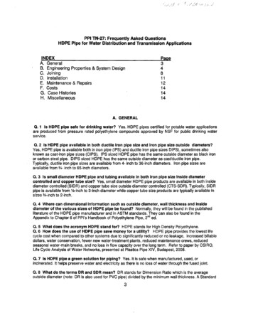
IntroductionThe CLINiC family of products from Iron Bow Healthcare Solutions consists of purposebuilt telehealth devices that enable the delivery of healthcare clinical evaluation,communications and observation from a distance.This user guide covers the assembly and installation of the Vidyo CLINiC configured forObservation (part # CLINiC-VC-10X24IR-B0x). For Administration and Configurationof the Iron Bow CLINiC, refer to the: VidyoRoom and VidyoPanorama 600Administrator Guides and VidyoRoom SE Deployment sThe CLINiC includes a hermetically sealed, high grade fanless computer with Windows10 Pro operating system, a high definition pan/tilt camera with a10x optical/10x digitalzoom, dual infrared illuminators for nighttime or darkened room operation and a 24” HDdisplay. The CLINiC camera, display and associated audio system enable high qualityvideo and audio calls between two parties or more.The CLINiC incorporates a standard VESA mounting hole pattern for installation oncommon wall mount brackets.Figure 1 - Video CLINiC with Optional Table StandYou can find additional CLINiC resources, support information and other relatedtelehealth services at www.ironbowhealthcare.com.8Copyright 2021 Iron Bow Technologies
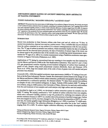
System DescriptionThe primary components of the Iron Bow CLINiC are shown below:1.2.3.4.5.System CameraRear Camera Cable CoverInfrared Illuminators24” System DisplaySystem Audio Bar6. Audio Deflector7. Wi-Fi Antennas8. Option Module Slots9. USB 3 Ports10. Network/Power ConnectorsFigure 2 - CLINiC Major System Components9Copyright 2021 Iron Bow Technologies
System InstallationThe Vidyo CLINiC for Observation is designed to be mounted on a wall arm mount in apatient room or common area. The standard VESA mounting hole pattern on the back ofthe unit fits many commercially available wall mount brackets. Prior to installation,please refer to Appendix A for mounting holes locations and dimensions. Please note, aPhillips #1 and #2 screwdriver is required for system assembly.Installing the CameraBefore using the system for the first time, you need to mount and connect the camera tothe mounting panel located on top of the CLINiC.To install the camera on the CLINiC:1. Remove camera assembly from packaging and place carefully on a table top.2. The system is supplied with a camera mounting plate and countersunk bolt toattach the camera to the mounting plate.Figure 3 - Attaching Camera to Mounting Plate3. Ensure the rear connectors of the camera are located at the rear of themounting plate, as shown below:Figure 4 - Attaching Mounting Plate to System Chassis10Copyright 2021 Iron Bow Technologies
4.Gently place the camera assembly on top of the CLINiC ensuring the holes onthe camera mounting plate line up with the mounting holes on top of theCLINiC.5.Attach the camera assembly to the CLINiC chassis using the four retainedPhilips head screws.Figure 5 - Connecting the two camera cables6. Connect the two cables that come out at the top of the CLINiC to thecorresponding connectors on the rear of the camera.7. Attach the rear camera cable cover using the two Phillips head screwsprovided.Figure 6 - Attaching rear camera cable cover8. Gently remove any packaging foam and tape from camera to complete systemassembly.11Copyright 2021 Iron Bow Technologies
Sound DeflectorThe CLINiC includes a removable sound deflector, installed underneath the control panelenclosure, as shown below.Figure 7 - Sound Deflector ShieldThe sound deflector improves the audio quality for CLINiC installations that are eitherwall-mounted or mounted on an arm, by deflecting the audio forward.Installing the Sound DeflectorFigure 8 - Installing Sound DeflectorLocate the three central Phillips head screws on the base section of the sound bar at the rear of the chassis.1. Remove the three Phillips head screws and align the deflector, pointing forward, with thethree screw holes and replace screws to secure shield in place.12Copyright 2021 Iron Bow Technologies
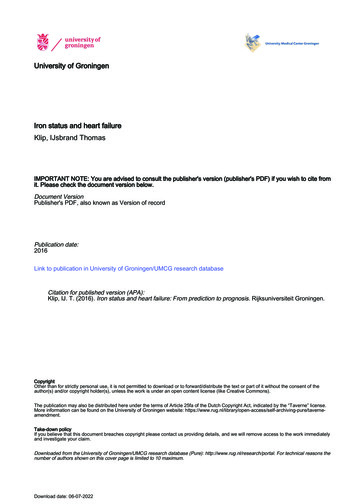
ConnectionsThe base CLINiC includes an AC power inlet, an Ethernet port for connecting to a wirednetwork, several USB 3 ports for connecting external devices including akeyboard/mouse, which may be required for setting up the CLINiC system.Left Side View1. IEC Main power inlet2. DB9 Expansion control port(future use)3. 10/100/1G Ethernet port4. USB 3 Port (keyboard/mouse)Right Side View5. 2 x Display USB 3 ports(inactive - for future use)6. USB 3 port (module blank plate)7. USB 3 port (module blank plate)8. 2 x Wi-Fi Antenna portsFigure 9 - Connection Ports13Copyright 2021 Iron Bow Technologies
Wi-Fi Network OperationThe CLINiC can be connected to either a wired or wireless (Wi-Fi) network. To operatefrom a Wi-Fi network, the two supplied antennas need to be attached to the system.Figure 10 – Location of WiFi AntennasInstalling the Wi-Fi Antennas1. Locate the two Wi-Fi antenna connectors on top of the CLINiC chassis.These are adjacent to the left and right infrared illuminators.Figure 11 - Installing W-Fi Antennas2. Install the two supplied Wi-Fi antennas by aligning them with the threadedmating connectors on top of the CLINiC chassis and gently screw them intoplace.14Copyright 2021 Iron Bow Technologies
Getting StartedPowering On and OffConnect any required peripherals to the CLINiC before connecting to AC power.Powering On the CLINiCTo power on the CLINiC: Connect the CLINiC to AC power. This will automatically power on theintegrated computer, camera and display of the CLINiC. A splash screen will bedisplayed within several seconds.Waking Up the CLINiCThe system goes to sleep after a set period with no activity. This value can be changedfrom the Settings menu of the VidyoRoom administrator user interface (Admin UI)To wake up the CLINiC: The CLINiC will automatically wake up on receipt of an incoming call, or bypressing any button on the infrared remote control.Powering Off the CLINiCPowering off the CLINiC is typically unnecessary. Most video endpoints remainconnected to the network and in stand-by mode until a call is placed or received.However, you may need to power off the CLINiC if you need to move the CLINiC to adifferent room.To power off the CLINiC: Disconnect the CLINiC from AC power.Restarting the CLINiCYou can restart the CLINiC by powering off and powering on the CLINiC.Connecting to the NetworkBefore you can make and receive video calls with the CLINiC, you must connect the unitto the network. There are two ways you can connect to the network: using the integratedWi-Fi with external antenna, or using the 10/100/1G Ethernet port.To connect the CLINiC to a Wi-Fi network, please refer to the: VidyoRoom andVidyoPanorama 600 Administrator Guides and VidyoRoom SE Deployment s15Copyright 2021 Iron Bow Technologies
CLINiC Software Set Up & AdministrationThe CLINiC is supplied as standard with a Windows 10 Pro operating system and VidyoRoomSE software application version 20.3.xx, or later. For further set up details on the CLINiC, pleaserefer to “SE Installation Guide” and the “VidyoRoom Software Edition Deployment Guide”.These documents includes links to all set up details of the Vidyo software application installed inyour system. This document can be accessed nfiguring the Application ModeThe Admin UI Settings tab allows the system application mode to be set as either Kiosk orAppliance: Kiosk mode prevents the VidyoRoom application from modifying the OS and allows users toexit the app from the OnScreen UI. This mode is the default Appliance mode will lock down the system by preventing Windows updates fromautomatically occurring, disables certain Windows notifications, creates inbound firewallrules for sharing, disables some special keys on the keyboard, hides the Task Bar, and more.16Copyright 2021 Iron Bow Technologies
Appendix #1: System SpecificationsDisplayType23.8” IPS LEDNative Resolution1920 x 1080Viewing Angle H/V178 /178 ControlControl OptionsOptional Tethered Remote Full Controller amd Volume ControlDB9 expansion control port (for future use)Control PortsUser supplied Keyboard / Mouse can be connected to USB 3 PortsVideo Input/OutputInputIron Bow IBHC-04 camera 10x optical/10x digital zoom3 x USB3 PortOutput1 x Display port (dedicated to display)Audio Input/OutputInputIntegrated beam-forming quad microphone arrayOutputIntegrated stereo speakers; 2 x 5 WattsNetwork1 x 10/100/1G Ethernet & Realtek Dual Band 802.11 a/b/g/n/ac Wi-FiDimensions/WeightWxHxD21.16" x 19.75" x 4.25" (Excludes Sound Deflector & Rear Cradle)AccessoriesSound Deflector: 1.25" HighOptional Rear Controller Cradle: 1.25" DeepWeight24 poundsMountingCompatible with 100mm x 100mm VESA mounts (refer to Appendix)ElectricalAuto Sensing Power Supply: 110-120VAC 60Hz, 1.67A17Copyright 2021 Iron Bow Technologies
Appendix #2: Mounting InformationThe following diagram is not to scale & is provided for dimensional information only.Figure 12 - Rear Mounting Locations18Copyright 2021 Iron Bow Technologies
Appendix #3: Optional Control DevicesThere are two optional tethered controller savailable for this product, as outlined below:Part NumberDescriptionACC-V-VOLCTRL-A01 Tethered volume-control remote forVidyo-based vCLINiC and MedViewproducts.Compatible VC-10XIR-XXXACC-V-REMOTE-A01Tethered remote control for Vidyo-based CLINiC-VC-10XIR-XXXvCLINiC and MedView XXACC-V-VOLCTRL-A01 Tethered Remote Volume ControlThe remote volume control is supplied with an integrated 2 feet long,retractable coiled cable that extends to typically 5 feet. The cable can beconnected to any of the USB ports on the system, prior to powering onthe system.Adjusting Speaker VolumeTo increase speaker volume: Press and hold the “ ” button on the hand-held volumecontrol until the desired sound level is achieved.To decrease speaker and headphone volume: Press and hold the “-“ button on the hand-held volumecontrol until the desired sound level is achieved.Figure 13 - TetheredVolume Control Layout“Escape (esc)” functionIn some cases, the screen may pop up messages that users will want to remove. This canbe done by plugging in a keyboard and pressing the esc key. Alternatively, the remotecontrol allows users to press the and – buttons simultaneously to send an “esc”keystroke to the computer.19Copyright 2021 Iron Bow Technologies
ACC-V-REMOTE-A01 Tethered Remote ControllerThe remote control is supplied with an integrated 2 feet long, retractablecoiled cable that extends to typically 5 feet. The cable can be connectedto any of the USB ports on the system, prior to powering on the system.Control FeaturesConnect - Answer call or place call to selected directory location which has been previouslystored.Disconnect - End or reject call.Video Privacy - Stop the video transmission from the CLINiC main camera during a call, orrevert to normal video transmission. This does not affect a preenetation video source.Transmit Presentation Source - Display and transmit video images from a connected UVCdevice compatible with the Vidyo application. Transmission is stopped by a second selection.Zoom In/Zoom Out - Zoom main camera in or out.Up/Down/Left/Right- When not in a call:navigate throughmenus; When in acall: pan and tilt themain camera.Self-View - Enable ordisable self-viewmode.Volume Up/Down –Increase or Decreasespeaker volume.Mic Mute - Mute orunmute microphone.Figure 14 - Tethered Remote Control Layout20Copyright 2021 Iron Bow Technologies
Installing Tethered Remote ControllerThe optional Vidyo CLINiC tethered controller conects to the system via a USB port and uses acable clamping arrangement to ensure that it is not accidently disconnected. A cradle is suppliedto store the controller when not in use which can either be wall mounted using the twoscrews/wall plugs provided, or it can be installed on the rear of the CLINiC System.To install the controller and cradle on the Vidyo CLINiC:1. Unpack controller and cradleassembly from packaging2. Align cradle mounting holes withrear chassis attachment points (1)and attach with supplied screws3. Remove cable clamp screw (2), feedremote cable through clamp and reattach using existing screw4. Identify USB 3 port on side ofchassis (3) and connect remotecontroller cableFigure 15 - AttachingControllerFigure 16 – ControllerAssembly21Copyright 2021 Iron Bow Technologies
Tethered Controller Cradle Location / DimensionsFigure 17 – Cradle Rear LocationFigure 18 – Cradle Dimensions22Copyright 2021 Iron Bow Technologies
-Page Intentionally Left Blank -23Copyright 2021 Iron Bow Technologies
2303 Dulles Station Boulevard, Suite 400Herndon, VA 20171Toll: 800.338.8866Tel: 703.279.3000www.ironbowhealthcare.com24Copyright 2021 Iron Bow Technologies
3 Copyright 2021 Iron Bow Technologies Safety & Maintenance For your protection, please read these safety instructions completely before operating the equipment and .