Transcription
Iron Bow Vidyo CLINiC Installation and User GuideCLINiC-V-10X24IR-B0xDocument Version 3.3Copyright 2020 Iron Bow Technologies1
Copyright 2020 Iron BowTechnologies All Rights Reserved.Specifications subject to change without notice.For general inquiries, contact:Iron Bow Healthcare Solutions2303 Dulles Station Boulevard,Suite 400Herndon, VA lthcare.comFor support, contact:Iron Bow Client Service CenterToll: 833.476.6269 (833.IRONBOW)Email: CSC@ironbow.comCopyright 2020 Iron Bow Technologies2
ContentsTable of Figures . 4Introduction . 5System Description . 6System Installation . 6Installing the Camera . 7Installing System Controller. 10Sound Deflector . 11Installing the Sound Deflector . 11Connections . 12Wi‐Fi Network Operation . 13Installing the Wi‐Fi Antennas. 13Getting Started . 14Powering On and Off . 14Waking Up the Vidyo CLINiC . 14Powering Off the Vidyo CLINiC . 14Restarting the Vidyo CLINiC . 14Connecting to the Network . 14Vidyo CLINiC Software Set Up & Administration . 15Appendix #1: System Controller Functions . 16Appendix #2: Mounting Information . 20Specifications. 21Copyright 2020 Iron Bow Technologies3
Table of FiguresFigure #Figure #Figure #Figure #Figure #Figure #Figure #Figure #Figure #Figure #Figure #Figure #Figure #Figure #Figure #Figure #Figure #Figure #Figure #Figure #Figure #Figure #Figure #Figure #Figure #Figure #1234567891011121314151617181920212223242526Vidyo CLINiC with optional Table StandVidyo CLINiC System ComponentsAttaching Camera to Mounting PlateAttaching Camera Mounting Plate to System ChassisConnecting the two camera cablesAttaching rear camera cable coverAttaching ControllerController AssemblyAligning CradleAttaching CradleAttaching Cable ClampSound DeflectorSound Deflector Screw LocationInstalling Sound DeflectorSystem Connection PortsLocation of Wi‐Fi AntennasInstalling Wi‐Fi AntennasSystem Controller Admin UI SettingsExample of “On Screen” IconsMute Functions IconsSource Available IconsSource Transmission IconsSystem Function IconsTethered Remote Controller KeysRear System DimensionsLeft Side View of System . . . . . . . . . . . . . . . . . . . . . . . . . .Copyright 2020 Iron Bow 616172020
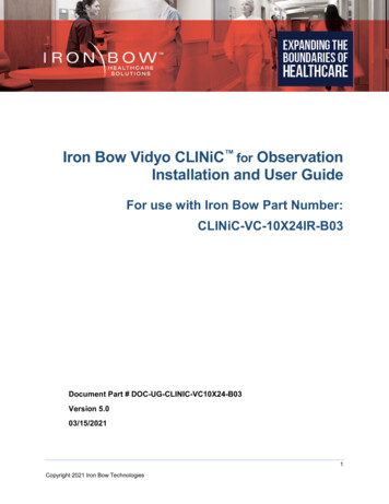
IntroductionThe CLINiC family of products from Iron Bow Healthcare Solutions consists ofpurpose built telehealth devices that enable the delivery of clinical healthcarefrom a distance.This user guide covers the assembly and installation of the second generationVidyo CLINiC, part # CLINiC-V-10X24IR-B0x. This generation of productincorporates a hermetically sealed, high grade fan less computer, a highdefinition pan/tilt camera with a10x optical/10x digital zoom, dual infraredilluminators for nighttime or darkened room operation and a 24” HD display.The Integrated sound bar incorporates a quad beamforming microphone arrayplus a full spectrum echo canceller, twin channel audio amplifier and dualspeakers. Standard room system controls are available to the user via a hand heldtactile membrane control panel which is connected to the system via a coiledcable.Figure 1 – Vidyo CLINiC with optional Table StandYou can find additional CLINiC resources, support information and other relatedtelehealth services at www.ironbowhealthcare.com.Copyright 2020 Iron Bow Technologies5
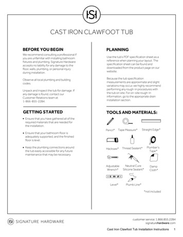
System DescriptionThe primary components of the Iron Bow Vidyo CLINiC are shown below:Figure 2 – Vidyo CLINiC System Components1.2.3.4.5.6.System CameraInfra‐Red Illuminator (1 of 2)Wi‐Fi Antenna (1 of 2)Camera rear cable coverIntegrated 24” LED DisplayHand Held Controller7. Electronic Stethoscope Input8. Power/Network Connectors9. HDMI (PC) Input10. USB 3 (Horus Scope) Input11. Sound Deflector12. Integrated MicrophonesSystem InstallationThe Vidyo CLINiC is designed to be mounted on a stable supporting structure thatprevents it from being knocked over or dropped. The standard VESA mounting holepattern on the back of the unit fits many commercially available wall mount brackets,desk stands and mobile carts. Prior to installation, please refer to Appendix A formounting holes locations and dimensions. Please note, a Phillips #1 and #2 screwdriveris required for system assembly.Copyright 2020 Iron Bow Technologies6
Installing the CameraBefore using the system for the first time, you need to mount and connect the camera tothe mounting panel located on top of the Vidyo CLINiC.To install the camera on the Vidyo CLINiC:1.Remove camera assembly from packaging and place carefully on a tabletop.2.The system is supplied with a camera mounting plate and countersunkbolt to attach the camera to the mounting plate.3.Ensure the rear connectors of the camera are located at the rear of themounting plate, as shown below:Figure 3 – Attaching Camera to Mounting Plate4.Gently place the camera assembly on top of the Vidyo CLINiC ensuringthe holes on the camera mounting plate line up with the mounting holeson top of the Vidyo CLINiC chassis.Copyright 2020 Iron Bow Technologies7
Figure 4 – Attaching Mounting Plate to System Chassis5.Attach the camera assembly to the Vidyo CLINiC chassis using the fourprovided Philips head screws.Figure 5 – Connecting the two Camera Cables6.Connect the two cables that come out at the top of the Vidyo CLINiC tothe corresponding connectors on the rear of the camera.7.Attach the rear camera cable cover using the two Phillips head screwsprovided.Copyright 2020 Iron Bow Technologies8
Figure 6 ‐ Attaching rear camera cable cover8.Gently remove any packaging foam and tape from camera to completesystem assembly.Copyright 2020 Iron Bow Technologies9
Installing System ControllerThe Vidyo CLINiC utilizes a tethered controller that operates all local room functions. Thecontroller attaches to the system via a USB port and uses a cable clamping arrangement to ensurethat it is not accidently disconnected.A rear mounting cradle is supplied with the system to store the controller when not in use or whenthe system is moved from one location to another.To install the controller and cradle on the Vidyo CLINiC:1. Unpack controller and cradleassembly from packaging2. Align cradle mounting holes withrear chassis attachment points (1)and attach with supplied screws3. Remove cable clamp screw (2),feed remote cable through clampand re-attach using existing screw4. Identify USB 3 port on side ofchassis (3) and connect remotecontroller cableFigure 7 ‐ Attaching ControllerFigure 9 – Aligning CradleFigure 8 – Controller AssemblyFigure 10 – Attaching CradleFigure 11 – Attaching Cable Clamp10Copyright 2020 Iron Bow Technologies
Sound DeflectorThe Vidyo CLINiC includes a removable sound deflector, which can be installedunderneath the sound bar as shown in Figure 12.Figure 12 ‐ Sound DeflectorThe sound deflector improves the audio quality for the Vidyo CLINiC installations that are eitherwall-mounted or mounted on an arm, by deflecting the audio forward.Installing the Sound DeflectorFigure 13 ‐ Sound Deflector Screw LocationFigure 14 – Installing Sound DeflectorLocate the three central Phillips head screws on the base section of the sound bar at the rear ofthe chassis.1. Remove the three Phillips head screws and align the deflector, pointing forward, with thethree screw holes and replace screws to secure shield in place.11Copyright 2020 Iron Bow Technologies
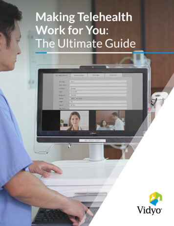
ConnectionsThe Vidyo CLINiC includes an AC power inlet, an Ethernet port for connecting to a wirednetwork, two USB 3 ports for connecting the system controller plus an externalexamination device, such as a Horus Scope and an HDMI Video Input for connection ofan external PC.If it is necessary to attach a standard PC keyboard/mouse for system set up, the two USB 3ports designated for the controller and a Horus Scope, can be utilized for connection ofthese devices. Once set up has been completed, the keyboard/mouse should bedisconnected and the system controller and Horus Scope re-connected. The system shouldthen be power cycled to ensure correct operation.Left Side View1. IEC Main power inlet2. DB9 Expansion control port (forfuture use)3. 10/100/1G Ethernet port4. Electronic Stethoscope InputRight Side View5.6.7.8.9.Controller USB 3 portDisplay ports (for future use)2 x Wi‐Fi Antenna portsHDMI Video Input (PC Usage)USB 3 Port (Horus Scope Input)Figure 15 – System Connection Ports12Copyright 2020 Iron Bow Technologies
Wi-Fi Network OperationThe Vidyo CLINiC can be connected to either a wired or wireless (Wi-Fi) network. To operatefrom a Wi-Fi network, the two supplied antennas need to be attached to the system.Figure 16 ‐ Location of Wi‐Fi AntennasInstalling the Wi-Fi Antennas1. Locate the two Wi-Fi antenna connectors on top of the Vidyo CLINiCchassis. These are adjacent to the left and right infrared illuminators.Figure 17 ‐ Installing Wi‐Fi Antenna2. Install the two supplied Wi-Fi antennas by aligning them with the threadedmating connectors on top of the Vidyo CLINiC chassis and gently screw theminto place.13Copyright 2020 Iron Bow Technologies
Getting StartedPowering On and OffConnect any required peripherals to the Vidyo CLINiC before connecting to AC power.Powering on the Vidyo CLINiCTo power on the Vidyo CLINiC:Connect the Vidyo CLINiC to AC power. This will automatically power on theintegrated computer, camera and display of the Vidyo CLINiC. A splash screenwill be displayed within several seconds.Waking Up the Vidyo CLINiCThe system goes to sleep after 10 seconds with no activity. This value can be changedfrom the Settings menu of the VidyoRoom administrator user interface (Admin UI) Towake up theVidyo CLINiC:The Vidyo CLINiC will automatically wake up on receipt of an incoming call, orby pressing any button on the controller.Powering Off the Vidyo CLINiCPowering off the Vidyo CLINiC is typically unnecessary. Most video endpoints remainconnected to the network and in stand-by mode until a call is placed or received.However, you may need to power off the Vidyo CLINiC if you need to move it to adifferent room.To power off the Vidyo CLINiC:Disconnect the Vidyo CLINiC from AC power.Restarting the Vidyo CLINiCYou can restart the Vidyo CLINiC by powering off and powering on the Vidyo CLINiC.Connecting to the NetworkBefore you can make and receive video calls with the Vidyo CLINiC, you must connectthe unit to the network. There are two ways you can connect to the network: using theintegrated Wi-Fi with external antenna, or using the 10/100/1G Ethernet port.To connect the Vidyo CLINiC to a Wi-Fi network, please refer to VidyoRoom andVidyoPanorama 600 Administrator Guide,14Copyright 2020 Iron Bow Technologies
Vidyo CLINiC Software Set Up & AdministrationThe Vidyo CLINiC is supplied as standard with a Windows 10 Pro operating system andVidyoRoom SE software application versions 19.3.xx. For further set up details on theVidyo CLINiC, please refer to “VidyoRoom and VidyoPanorama 600 Administrator Guidesand VidyoRoom SE Deployment Guides. This document includes links to all set up detailsof the Vidyo software application. This document can be accessed r specific information on the Vidyo software application set up, the user document that needsto be accessed is the VidyoRoom Admin Guide 19.3, which can be accessed from the deploymentguide specified above, or directly from this link:VidyoRoom AdminGuide 19.3.0.pdf (2 MB)Configuring the Application ModeThe Admin UI Settings tab allows the system application mode to be set as either Kiosk orAppliance: Kiosk mode prevents the VidyoRoom application from modifying the OS and allowsusers to exit the app from the OnScreen UI. This mode is the default Appliance mode will lock down the system by preventing Windows updates fromautomatically occurring, disables certain Windows notifications, creates inbound firewallrules for sharing, disables some special keys on the keyboard, hides the Task Bar, andmore. (Refer to: VidyoRoom AdminGuide 19.3.0.pdf)Configuring the System ControllerThe default set up within the Admin UI for correct operation of the system controller is shownbelow. Any changes to this configuration will result in the control keys malfunctioning.Figure 18 – System Controller Admin UI Default Settings15Copyright 2020 Iron Bow Technologies
Appendix #1: System Controller FunctionsA tethered hand held controller is supplied as standard with the Vidyo CLINiC, which canbe used to control and select standard system functions, including; make and receive calls,controlling the camera, volume and all other functions that may be required during a callbetween one or more sites.The operational controls are depicted below with an explanation of the operational usageof each. Several of the functions incorporate an on screen icon which is displayed in thetop right hand corner of the screen;Figure 19 – Example of “On Screen” IconsThere are three types of on screen icons used:Mute Functions:Audio and Video Mute icons are displayed in Red when either of these functions areactive:Figure 20:Mute Function IconsSource Input Functions:The system incorporates three source functions for external (client supplied) devices; PCor HDMI Video Source, Horus Scope, and electronic stethoscope. When these devices areconnected and available, a white icon for each appears, when transmission is active agreen icon is displayed: (The stethoscope icon is always displayed as available)Figure 21:Source Available IconsFigure 22:Source Transmission Icons:System Functions:System functions are available for camera Infra-Red (Nighttime) operation as well asputting the audio system into a Super Sensitive Mode:Figure 23:System Functions Icons16Copyright 2020 Iron Bow Technologies
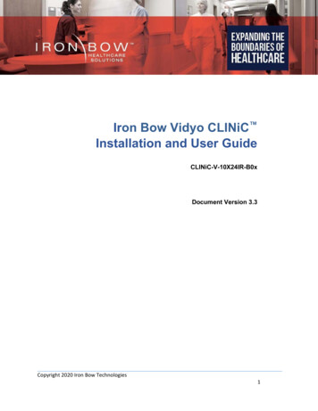
Figure 24 – Tethered Remote Controller KeysThe Arrow keys control camera up/down/left/right movement when the system is in a callWhen the system is not in a call, the arrow keys are used to move through the Vidyo onscreen contacts directoryWhen the system is in a call, the camera zoom in and out functions are controlled by the and - signsWhen the system is in a call, the volume functions are controlled by the and – signs. Avolume indicator bar is displayed on the bottom of the screen indicating the volume level17Copyright 2020 Iron Bow Technologies
The ESC (Escape) key is available to remove any unwanted system or network messagesthat can be automatically displayed by the network e.g. “New software update available”Camera infra-red operation has two states: (Daylight/Auto)State #1: Default State: Daylight operationState #2: Auto.When you click the infra-red button the Preview (self-view) will display the infrared icon either as Daylight or Auto and you can toggle between modes for up to 15seconds. If the system is in a call, the IR mode will display on its own.Super Sensitive Mode removes all of the audio filtering allowing every noise in theroom to be heard at the remote site(s), which may be required when listening for aspecific sound or audio tone.The Connect control is used to make a call and accept an incoming call. Thearrow can be used to move through the Vidyo on screen contacts directory and theby selecting the green call button a call is a launched to the selected location. Ifthe system is not in auto-answer, the connect key is used to accept an incomingThe Hang Up control is used to end a call. If the system is not in auto answermode, then the Hang Up control can be used to reject an incoming call from aremote site.Microphone Mute selection stops the room audio from being transmitted to theremote site. A second selection resumes the audio transmission. This control doesnot affect transmission of an electronic stethoscope.The Stethoscope control transmits the audio output from a connected electronicstethoscope to the remote location. On selection, the local room microphones areautomatically muted to ensure the stethoscope audio can easily be heard at theremote site without any background room noise. When the stethoscope is turnedoff, the room microphones are automatically activatedElectronic Stethoscope Notes: A digital Stethoscope with a 3.5 mm line output (e.g. theJEDMED Omni Scope) can be used with the system. The installed version of Vidyo softwaresupports the higher quality Opus audio algorithm which will only function if the remote codecuses the same audio algorithm.For Opus audio to operate the VidyoPortal & VidyoRouter must use software version 18.4.0or later. If any of these criteria are not met, the overall system will revert to using the lowerquality Speex audio algorithm.18Copyright 2020 Iron Bow Technologies
Camera Mute selection stops the image from the system main camera beingtransmitted to the remote site. A second selection resumes the cameratransmission. This control does not affect transmission of ancillary deviseconnected to the system such as a PC or Horus Scope.llThe Self View control is used to obtain an on screen view of the image from themain system camera which can be switched on or off by this control.Transmit PC sends the image from a connected PC or HDMI device to theremote site as a second image in conjunction with the main system camera. Theimage will automatically be shown as a window on the main screen. To endtransmission, select the control again or select the Horus Scope key, which willreplace the PC image with the Horus Scope image.Transmit Horus Scope sends the image from a connected Jed Med USB HorusScope to the remote site as a second image in conjunction with the main systemcamera. The image will automatically be shown as a window on the main screen.To end transmission, select the control again or select the transmit PC key, whichwill replace the Horus Scope image with the PC image.19Copyright 2020 Iron Bow Technologies
Appendix #2: Mounting InformationThe following diagrams are not to scale and are provided for dimensional information only.Figure 25 – Rear System DimensionsFigure 26 – Left Side View of System Detailing: Sound Deflector Dimensions Rear Controller Cradle Depth20Copyright 2020 Iron Bow Technologies
SpecificationsDisplayType23.8” IPS LEDNative Resolution1920 x 1080Viewing Angle H/V178 /178 ControlRemote ControlTethered Remote ControllerControl PortDB9 expansion control port (for future use)Keyboard/MouseFor installation a keyboard, mouse and USB hub required (end user supplied)Video Input/OutputInputIron Bow IBHC-04 camera 10x optical/10x digital zoom1 x HDMI Video Input (Designated for external PC connection)1 x USB3 Port (Designated for external Horus Scope connection)Output1 x Display port (dedicated to display)Audio Input/OutputInputIntegrated beam-forming quad microphone array1 x 3.5 mm Audio Input for Electronic StethoscopeOutputIntegrated stereo speakers; 2 x 5 WattsNetwork1 x 10/100/1G Ethernet & Realtek Dual Band 802.11 a/b/g/n/ac Wi-FiDimensions/WeightWxHxD21.16" x 19.75" x 4.25" (Excludes Sound Deflector & Rear Cradle)AccessoriesSound Deflector: 1.25" HighRear Controller Cradle: 1.25" DeepWeight23 poundsMountingCompatible with 100mm x 100mm VESA mounts (refer to Appendix)ElectricalAuto Sensing Power Supply: 100-240V 50/60Hz, 2A - 0.9A (100-240v)21Copyright 2020 Iron Bow Technologies
2303 Dulles Station Boulevard, Suite 400Herndon, VA 20171Toll: 800.338.8866Tel: 703.279.3000www.ironbowhealthcare.com22Copyright 2020 Iron Bow Technologies
Powering on the Vidyo CLINiC To power on the Vidyo CLINiC: Connect the Vidyo CLINiC to AC power. This will automatically power on the integrated computer, camera and display of the Vidyo CLINiC. A splash screen will be displayed within several seconds. Waking Up the Vidyo CLINiC The system goes to sleep after 10 seconds with no activity.