Transcription
AMS RADIOCARBON DATING OF ANCIENT ORIENTAL IRON ARTIFACTSAT NAGOYA UNIVERSITYTOSHIO NAKAMURA,1 MASAHIRO HIRASAWA,2 and KENZO IGAKl3ABSTRACT. We present here the current status of AMS dating of iron artifacts at Nagoya University. We initiallydevelopeda "wet" method of carbon collection from iron samples, consisting of a resistance furnace and a "wet"trapping of the evolvedCO2 with a saturated Ca(OH).solution, in which overall collection efficiency of carbon ranged from50 to 60%. To improvethe carbon-collection efficiency, we more recently constructed a "dry" system, consisting of an induction furnacefollowed by"dry" separation of the produced CO2 from combustion gases and conversion of the CO2 into a graphitetarget. We describehere mainly the performance of the "dry" separation system, tested using standard steel samples. We alsoreport previouslydetermined 14C dates on three ancient Oriental artifacts using the earlier "wet" procedure.INTRODUCTIONRecent iron production in blast furnaces utilizes coke from coal and oil, which are 14C-free. Inancient iron production, charcoal was used as a carbon source. Thus, a reliable date may be obtainedfrom the carbon contained in an iron artifact if it is almost contemporaneous with the iron production. The 14C age of carbon in metallic iron artifacts, which essentially implies the date of cutting thesource trees for the charcoal (more precisely, the date of formation of annual rings of the trees), canbe almost equal to the production date of the metallic iron, considering typical measurement uncertainties for 14C ages of ca. 80 yr in a routine measurement using a Tandetron accelerator mass spectrometer at Nagoya University (Nakamura et a1.1985).Applications of 14C dating by conventional beta-ray counting to iron samples was first initiated byvan der Merwe and Stuiver (1968) at the Yale Radiocarbon Laboratory. They used 0.5- and 1.5-literC02 gas proportional counters requiring several hundred milligrams of carbon from hundreds ofgrams of iron. Despite using small proportional counters (Harbottle, Sayre and Stoenner 1979;Sayre et a1.1979), large iron sample sizes of the order of tens of grams were still needed and poorprecision was obtained.Cresswell (1991,1992) first applied accelerator mass spectrometry (AMS) to 14C dating of iron artifacts at the IsoTrace Laboratory, Toronto, Canada. He constructed a system based on the design of vander Merwe and Stuiver (1968) in which carbon extraction, purification and graphite target preparationwas performed in a continuous operation. He obtained reliable 14C dates from ancient iron artifactson samples of only a few hundred milligrams. In Japan, Yoshida (1992) studied AMS 14C dating ofiron artifacts, using an AMS system at the University of Tokyo. However, he used only solid residuesfrom the acid treatment of iron samples and could analyze only high carbon cast-iron samples.As described by Igaki et al. (1994), we developed a carbon extraction system for metallic iron forAMS 14C dating. We initially constructed a "wet" method of carbon collection from iron samples,which uses a saturated Ca(OH)2 solution to trap CO2 produced by oxidizing iron samples with anelectric resistance furnace at 1200 C in a mullite tube in the presence of purified oxygen gas. Carbonfrom iron trapped as CaCO3 was then changed to CO2, by thermal decomposition at 850 C in a vacuum line, for routine graphite target fabrication (Kitagawa et al. 1993), to perform 14C AMS analyses at Nagoya University. The collection efficiency of carbon was rather low in the "wet" method,ranging from 50 to 60%. To achieve higher collection efficiency, we recently developed another'Dating and Materials Research Center, Nagoya University, Chikusa, Nagoya 464-01 Japan2School of Engineering, Nagoya University, Chikusa, Nagoya 464-01 Japan'Faculty of Engineering, Tohoku University, Aoba, Sendai 980 JapanProceedings of the 15th International 14C Conference, edited by G. T. Coo/c D. D. Harkness,B. F. Miller and E. M. Scott. RADIOCARBON, Vol. 37, No. 2,1995, P. 629-636https://doi.org/10.1017/S0033822200031131 Published online by Cambridge University Press629
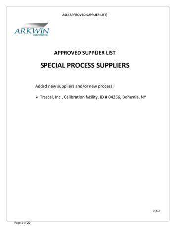
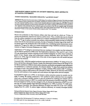
630T.Nakamura, M. Hirasawa and K. Igakisimple "dry" method by extracting carbon from iron samples and directly separating CO2 from thecombustion gas. Here we discuss the newly developed "dry" method, and some 14C dates for oriental iron artifacts determined using the earlier "wet" procedure.SAMPLE COMBUSTION AND CARBON EXTRACTION: "DRY METHOD"Combustion of Iron SamplesIron samples were oxidized using an induction furnace in the presence of purified 02. CO2 converted from carbon in the iron samples was collected in a gas bag along with 02. The CO2 was thenseparated from 02 and other impurity gases in a vacuum line.Figure 1 shows the combustion system for iron samples. An induction furnace, LECO HF-10,LECO Corporation, St. Joseph, Michigan, USA, can oxidize up to 2 g of iron at once. We normallyrequire 1 mg of carbon in the form of CO2 to produce a graphite target for the Tandetron spectrometer, in which only one cycle of carbon extraction is needed for iron samples with 0.05% carboncontent. This restriction in sample size does not affect ancient iron artifact samples, which usuallyhave higher carbon contents.Oxygen flow0012IU CombustionGas Flow10-ii13CombustionGasFig. 1. Schematic diagram of the iron combustion system: 1. oxygen gas cylinder; 2. heated copper oxide; 3. Ascarite to trapC02; 4. Anhydrone to trap H2O; 5. induction coil; 6. crucible; 7. quartz reaction tube; 8. molten oxide bath; 9. quartz wool totrap dust; 10. manganese oxide to trap SO2 and S03;11. three-way valve; 12. flow meter; 13. gas bag.Normal-grade and grade-A high-purity oxygen gas were tested for the combustion of iron samples.Possible carbon contamination of the oxygen gas was eliminated by passing the oxygen through aCuO wire mesh at 500 C, as well as a set of CO2 and water vapor absorbers (Ascarite of ca. 8-20mesh and Anhydrone of granular Mg(C104)2). Iron- and tungsten-oxide dust was trapped in a quartzwool filter, located just after the furnace. Sulfur oxide gases (SO2, SO3) and water vapor producedhttps://doi.org/10.1017/S0033822200031131 Published online by Cambridge University Press
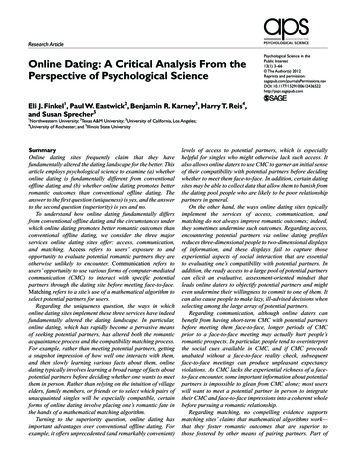
14C Dating of IronArtifacts at Nagoya University631by the combustion of iron samples were absorbed by granular Mn02 and Anhydrone,respectively.We used a 10-liter Tedlar bag, equipped with two inlets with rubber 0-ring seal stopcocks,to collectcombustion gas samples.We used pure graphite and four standard iron samples of different carbon content (4.67%,0.13%,0.05% and 0.0056%) to test the combustion system. Each iron sample was put in a ceramic crucible(#528-018, LECO) preheated at 1100 C for 10 h. The iron sample was placed in the crucible andheated at 600 C for 10 min in an electric oven to eliminate possible carbon contamination.Then wetook the crucible out of the oven, added an appropriate amount of combustion accelerant and placedit in the microwave furnace. The gas collection bag was connected to the combustionline via athree-way valve, as shown in Figure 1.After the iron sample was set in the furnace, residual air in the combustion line was removedbyflushing with ca. 30 liters of 02 gas at STP, monitoring the flow rate with a gas flow meter.The gasbag was then flushed by filling it with 02 and pumping02 out three times to eliminate atmosphericC02 contamination. When the flushed gas bag was empty, the02 flow rate was adjusted to 2 litersper minute and the induction furnace was ignited. The start of oxidation of the iron samplewasmarked by a decrease in 02 gas flow rate.Ten seconds after ignition of the furnace, the combustion gas was directed to the gas bag, andcollected for 2-3 min. Following this, the gas bag stopcock was closed and the tube connectedto thestopcock was closed with a pinch-cock.CO2 Extraction from Combustion Gas and Graphite PreparationWe tried to extract CO2 from the combustion gas on the same day as the combustion, to keepthe gassample free from any atmospheric CO2 contamination. However, for some samples, extraction wasperformed 1-3 days after combustion. The gas bag was connected to the vacuum line system with arubber tube, and the vacuum system and the connection tube were evacuated (Fig. 2). Once the system was evacuated, water traps 1 and 2 were cooled to -100 C with an ethanol/liquid nitrogen (liq.N2) mixture, and CO2 traps 3 and 4 with liq. N2. (Traps 2, 3 and 4 are U-shaped, 20 mm in diameterand 40 cm long, with many small glass fingers to increase the gas-trapping surface.) The combustiongas was then fed through the traps with a flow rate of 40 ml per minute, regulated by a mass-flowcontroller, by pumping out the non-C02 gases, mainly 02, with an oil rotary pump. A Pirani gaugeshowed ca.1 Ton at the outlet of trap 4. In a few hours, after the combustion gas was completelyprocessed, CO2 collected in traps 3 and 4 was again separated from water vapor and SO2 using anormal-pentane trap with a melting point of -131 C. The amount of CO2 collected was determinedfrom the pressure of CO2 gas expanded in a calibrated volume, using a pressure transducer. The CO2sample was then sealed in a Pyrex tube of 6 mm diameter for further analyses.The CO2 from ca.1 mg of carbon separated from the iron samples was made into a graphite targetby reducing with hydrogen on iron powder at 650 C, as described by Kitagawa et at. (1993). The14C content of thegraphite was then measured with a Tandetron spectrometer at Nagoya University(Nakamura et a1.1985, 1992).RESULTS AND DISCUSSIONCarbon Collection Efficiency and14CBackgroundWe tested the carbon collection efficiency and 14C background of the carbon extraction system,using standard steel samples specially designed for carbon content analysis: 4.67%C steel suppliedhttps://doi.org/10.1017/S0033822200031131 Published online by Cambridge University Press
632T.Nakamura, M. Hirasawa and K. IgakiLIPirani gaugeMass flow controllerTo vacuum pumpvvvvTraps:123Transducer4SealedFig. 2. Schematic diagram of the CO2 separation system. See text for details. Traps 1, 2. Ethanol/liquid N2 to trap H2O at-100 C; Traps 3, 4. liquid N2 to trap CO2.by LECO Corporation, 0.13%C (JSS-023-3), 0.05%C (JSS-201-1O) and 0.0056%C (JSS-200-11)steels of Japanese iron and steel-certified reference materials supplied by the Iron and Steel Instituteof Japan, and Sri Lanka ore graphite. Nearly equal amounts of combustion accelerant (Lecocel 2HP(W Sn), LECO Corporation) were added to steel samples weighing 1 g, while ca.1 g of accelerantwas added to samples weighing 1 g.As shown in Table 1, the carbon collection efficiency for steel samples weighing 1 g is 80%,except for runs 7 and 8. Carbon collection efficiency is 64-70% for 4.67%C steel, systematicallylower than that for lower-carbon samples. The efficiency for graphite powder is much lower, 5465%. We suspect that the combustion of carbon for high-carbon samples may not be complete, perhaps because the temperature was not high enough. Radio-frequency induction may not work wellfor small amounts of iron. Cresswell (personal communication, 1994) suggested another possibility.High-carbon samples would oxidize rapidly, and a surface skin of wustite/magnetite can form, hindering the diffusion of interior carbon to the surface for oxidation. He therefore suggests using aniron accelerant rather than a tungsten and tin mixture to prolong the melt at high temperature duringthe combustion. We need more tests to achieve higher collection efficiency for high-carbon samples.Aliquots of CO2 separated from the combustion gas from runs 3, 4 (4.67%C) and 11,12 (0.13%C)were analyzed for 13C/12C ratios with a Finnigan Mat 252 mass spectrometer, giving 813CPDB valuesof -25.9, -25.8, -23.4 and -23.3%o, respectively. The b13CPDB values for the 4.67%C iron standardare lower by 2.59% than those for the 0.13%C standard. This indicates that the sources of carbon inthe two standards are different, i.e., they both derived from carbon in coal or oil, but were collectedfrom different coal mines or oil wells.Since standard steel samples are manufactured both in modern blast furnaces using iron ore and cokeproduced from coal, and in vacuum-induction furnaces using electrorite iron and oil-coke from oil ashttps://doi.org/10.1017/S0033822200031131 Published online by Cambridge University Press
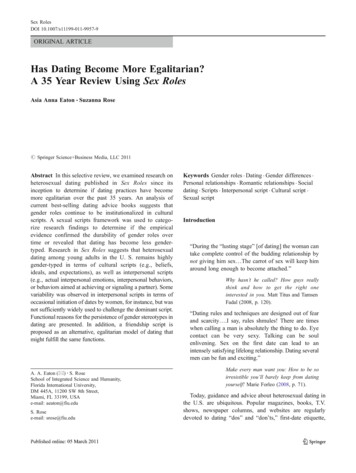
14C Dating ofIron Artifactsat Nagoya University633Extraction Efficiency of Carbon and 14C Background for the Combustion and "Dry" CO2Separation SystemTABLE 1.Lab(NTUA-)/run nos.* SampleFeSample Carbon Yieldsample amount content of CO2(%C)(g)(mg)(mg C)EEt324811 1001000.00113254/2GraphiteGraphite1.070.0020 1.970.6951.05665542.81 0.34 28,700 9603.11 0.52 27,900 13403255/3 3256/4Leco FeLeco Fe4.674.670.09690.05374.522.513.181.61670641.32 0.09 34,770 5605.01 0.22 24,070 350JSS FeJSS FeJSS Fe320718 JSS Fe3224/9 JSS Fe3226/10 JSS Fe0.130.130.130.130.130.131.001.301.001.300.9683 1.321.0168 1.321.0075 1.310.9648 1.251.121.060.9320.8161.1511.08286826288865.20 0.183.93 0.266.43 0.192.67 0.113.45 0.383.66 0.123214/11 3227/12JSS FeJSS 33225/14JSS FeJSS Fe0.050.052.002.00781.001.000.7970.9728097/15JSS Fe0.0056 /63206/71.00(%)7114Cactivity(pMC)Apparent 14Cage (yr BP)813CPDB(%o)Moderncarboncontamination(mg 0.020.040.043.08 0.11 27,960 3002.33 0.10 30,230 350-23.4-23.30.070.0510.49 0.33 18,120 2509.33 0.31 19,060 270---0.080.0923,760 28026,000 53022,060 24029,120 33027,060 89026,580 270*Run numbers are also indicated in Fig. 3.tExtraction efficiency C02 extraction was performed immediately following combustion of iron samples. For the other runs, the extractionwasdone 1-3 days after combustion.raw materials, they should be completely 14C-free. However, carbon extracted in our system contained an appreciable amount of 14C, ranging from 1 to 10% modern carbon (pMC), giving apparentages from 18 to 35 ka, as shown in Table 1. A steel sample with 4.67%C (run 3) showed the lowest 14Cactivity. However, run 4 on the same steel showed higher 14C activity. In the latter case, the CO2extraction was performed 3 days after the combustion. Thus, CO2 in the combustion gas may havebeen contaminated by atmospheric CO2 through the container bag. For runs 2, 5, 6, 7,12,13 and 14,CO2 was extracted the day after the combustion. Some of them show high 14C activities, perhapsbecause of similar contamination to run 4.14C activities for six samples in which CO2 was extractedimmediately following combustion ranged from 1.32 to 3.66 pMC, with an average of 2.8 0.8 pMC.We estimated the amount of modern carbon required to contaminate each 14C-free sample by multiplying yield of CO2 and 14C activity. As shown in Table 1, for all samples (except for run 11) forwhich CO2 was extracted from the combustion gas on the same day of the combustion, the contamination of modern carbon is 0.05 mg. For the other samples it is consistently above 0.05 mg, almostreaching 0.09 mg, suggesting a strong correlation between 14C background and storage length of thecombustion gas. Figure 3 shows the correlation between CO2 yield and 14C activity. Steel samplesof 0.05%C show relatively high 14C content compared to that of other standard materials. This high14C concentration possiblyresulted from inherent 14C contamination of the sample itself, though the14C contamination duringthe storage of the combustion gas may be the dominant source.Cresswell (1992) suggested that normal steel whose carbon content is 0.65-0.96%C showed a 14Cbackground of 2.2-2.7 pMC when medical-grade oxygen way used for steel combustion. The use ofhttps://doi.org/10.1017/S0033822200031131 Published online by Cambridge University Press
634T. Nakamura, M.Hirasawa and K. Igaki130014705400a2 012081CO2T1234YIeldlmgCFig. 3. Correlation between CO2 yield and 14C activity for standard iron materials.Numbers in the figure indicate run numbers given in Table 1:1, 2 graphite; 3,4 4.67%C; 5-12 0.13%;13,14 0.05%C. Closed square indicates runs processedthe same day, as described in the text.high-purity oxygen markedly reduced the 14C background to 0.47-0.82 pMC. We also tested thecombustion system with both normal-grade oxygen (99.9%) and grade-A high-purity oxygen(99.99%), but could find no improvement in the 14C background level. Commercial specificationsindicate that the CH4 content of both oxygens is 30 ppm, and concentrations of hydrocarbon, CO2and CO are 10 ppm for higher-grade oxygen. It seems reasonable that both oxygens show no difference, because they contain almost equal carbonaceous contaminants that may not be removedcompletely at the inlet trap of the combustion system. We recently discovered commercially available ultra-pure oxygen (99.9999%), whose CH4 and CO2 contents are 0.05 and 0.01 ppm, respectively. We hope the 14C background will be reduced when the ultra-pure oxygen is used for combustion, as in the study by Cresswell (1992).14CDates of Oriental Iron ArtifactsWe previously used the "wet" separation method (Igaki et al. 1994) to measure 14C dates on carbonseparated from three oriental artifacts: a Japanese sword; a planing adze; and an iron hook. Table 2summarizes information on these dates. We used the CalibETH 1.5b program (Niklaus 1991;Niklaus et al. 1992) and dendro-calibration data of Stuiver and Pearson (1993) to calibrate the 14Cdates measured in this study.The sword is believed to have been made by the "Maru-kitae" method, forging the original iron asa whole. This method was used before the appearance of the more elaborate composite forgingmethod of covering a soft steel core with hard steel. The forging age of the sword was estimated historically to be from the late Kamakura (AD 1192-1333) to early Muromachi (AD 1336-1573) periods. The calibrated 14C date, cal AD 1021-1263, although a bit older, is still consistent with the earlier historical estimate (Igaki et a1.1994).https://doi.org/10.1017/S0033822200031131 Published online by Cambridge University Press
14C Dating of Iron ArtifactsTABii 2. AMS14CSampleNo. description123Japanese swordPlaning adze(cast iron)Iron hook fromHoryuji Templeat Nagoya University635Dates for Three Oriental Iron ArtifactsSampleweight content(g)datesage2.270.934.531501607th to early8th centuryrange AD/no.BP)110(94.8)483-508 (5.2)(97.3)845-853 (2.7)The cast-iron adze is thought to have been originally unearthed in China. An X-ray picture of thesample revealed many internal pores, some of which contained fine iron oxide powder. As partofthe tip of the adze is broken, we assume that it had been used. The calibrated range, cal AD 119-457,corresponds to the Late Han and Jin dynasties in China. This is also the period when cast-iron production was fully developed in China, and nowhere else in the world (Igaki et a1.1994).The Horyuji Temple at Ikaruga, Nara Prefecture, Japan, is the oldest wooden building in the world.The temple was first constructed in AD 607; it burned down in AD 670, and was rebuilt by the earlyeighth century. The iron hook was found in the five-roofed pagoda. The calibrated range, cal AD604-814, is consistent with the rebuilding date of the tower. Discussion of this iron artifact will bepresented elsewhere in more detail.CONCLUSIONWe constructed a combustion and CO2 separation system for AMS 14C dating of iron artifacts.Wesummarize the performance of the system as follows:recovery efficiencies for 0.13%C and 0.05%C steel samples typically ranged from 80 to90%. Pure graphite and 4.67%C iron samples showed lower efficiencies of 50 to 70%, perhapsbecause of the small size of the iron samples used for combustion. For small sample sizes, aninduction furnace may not produce high enough temperatures to smelt iron. We must also testother possible ways of achieving higher collection efficiencies for high-carbon samples.1. CO22. The 14C background of the preparation system was tested using standard steel samplesproduced in blast furnaces using coke from coal and oil. The 14C background showed a dependence on the storage history of the separated CO2. When CO2 was separated from the combustion gas immediately after combustion, the 14C activity of the sample ranged from 1.32 to 3.66pMC (avg. 2.8 0.8 pMC). This range was systematically lower than for samples with CO2separation occurring on the following day or a few days after combustion.3. Theoretically, 14C contamination of 2.8 0.8 pMC gives an apparent 14C age 63 yr too youngfor a 2000-yr-old sample. This difference is almost equal to or slightly lower than the uncer-tainties of 14C dates measured routinely by the Tandetron spectrometer at Nagoya University(Nakamura et al. 1985). We are continuing our attempt to reduce the 14C background to thelevel of the IsoTrace Laboratory, Toronto, Canada, by using ultra-high-purity oxygen for thecombustion of iron samples.4. Three samples of oriental iron artifacts, weighing 2.27, 0.93 and 4.53 g, were prepared by the"wet" procedure and successfully AMS-dated. The calibrated 14C dates are consistent withtheir historical age estimates, and provide constraints on their fabrication ages. We need, how-https://doi.org/10.1017/S0033822200031131 Published online by Cambridge University Press
636T.Nakamura, M. Hirasawa and K. Igaki14C datesever, to test performances of 14C trapping by the "wet" method to rely fully on theobtained in this study.Further 14C analyses of ancient iron artifacts are required, along with metallurgical analyses to helpdetermine the source of the iron. As suggested by Cresswell (1992), chemical impurities in iron artifacts may help identify the origin of their raw materials.ACKNOWLEDGMENTSWe appreciate our fruitful discussions with Dr. R. G. Cresswell of the Australian National University. We thank graduate students M. Kato, T. Ota and R. Kakimoto of the School of Engineering,Nagoya University, for their contribution to the early stage of this study. This work was supportedpartly by Grants-in-Aid for Scientific Research from the Ministry of Education, Science and Culturein 1993-1994 (05835006).REFERENCESCresswell, R. G. 1991 The radiocarbon dating of ironartefacts using accelerator mass spectrometry. Historical Metallurgy 25: 78-85.1992 Radiocarbon dating of iron artifacts. In Long,A. and Kra, R. S., eds., Proceedings of the 14th International 14C Conference. Radiocarbon 34(3): 898905.Harbottle, G., Sayre, E. V. and Stoenner, R. W. 1979Carbon-14 dating of small samples by proportionalcounters. Science 206: 683-685.Igaki, K., Nakamura, T., Hirasawa, M., Kato, M., andSano, M. 1994 Radiocarbon dating study of ancientartifacts with accelerator mass spectrometry. Proceedings of the Japan Academy 70(B1): 4-9.Kitagawa, H., Masuzawa, T., Nakamura, T. and Matsumoto, E. 1993 A batch preparation method for graphite targets with low background for AMS 14C measurements. Radiocarbon 35(2): 295-300.Nakamura, T., Nakai, N., Sakase.,T. Kimura, M., Ohishi,S., Taniguchi, M., and Yoshioka, S. 1985 Direct detection of radiocarbon using accelerator techniques andits application to age measurement. Japanese JournalofApplied Physics 24:1716-1723.Nakamura, T., Nakazawa, T., Nakai, N., Kitagawa, H.,Honda, H., Itoh, T., Machida, T. and Matsumoto, E.1992 Measurement of 14C concentrations of stratospheric CO2 by accelerator mass spectrometry. Inhttps://doi.org/10.1017/S0033822200031131 Published online by Cambridge University PressLong, A. and Kra, R. S., eds., Proceedings of the 14thInternational 14C Conference. Radiocarbon 34(3):745-752.Niklaus, T. R. 1991 CalibETH 1.5b, Program for calibration of radiocarbon dates. Institute for IntermediateEnergy Physics, ETH, Zurich, Switzerland.Niklaus, T. R., Bonani, G., Simonius, M., Suter, M. andWolfli, W. 1992 CalibETH: An interactive computerprogram for the calibration of radiocarbon dates. InLong, A. and Kra, R. S., eds., Proceedings of the 14thInternational 14C Conference. Radiocarbon 34(3):483-492.Sayre, E. V., Harbottle, G., Stoenner, R. W., Washburn,W., Olin, J. S. and Fitzhugh, W. W. 1982 The carbon14 dating of an iron bloom associated with the voyages of Sir Martin Frobisher. American Chemical Society Symposium Series 176: 441-451.Stuiver, M. and Pearson, G. W. 1993 High-precisionbidecadal calibration of the radiocarbon time scale, AD1950-500 BC and 2500-6000 BC. In Stuiver, M.,Long, A. and Kra, R.S., eds., Calibration 1993. Radiocarbon 35(1):1-23.van der Merwe, N.J. and Stuiver, M. 1968 Dating iron bythe carbon-14 method. CurrentAnthropology 9:48-53.Yoshida, K. 1992 Measurement of 14C age by acceleratormass spectrometry. Bulletin of the National MuseumofJapanese History 38:171-198.
He obtained reliable 14C dates from ancient iron artifacts on samples of only a few hundred milligrams. In Japan, Yoshida (1992) studied AMS 14C dating of iron artifacts, using an AMS system at the University of Tokyo. However, he used only solid residues from the acid treatment of iron samples and could analyze only high carbon cast-iron samples.