Transcription
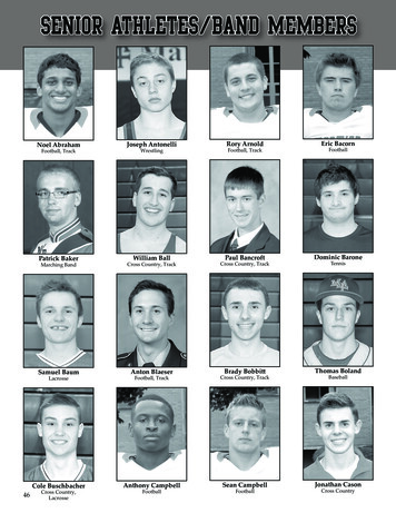
Dual band antireflection coatings for the infraredThomas D. Rahmlow, Jr.*a, Jeanne E. Lazo-Wasema, Scott Wilkinsonb, and Flemming TinkercaRugate Technologies, Inc., 353 Christian Street, Oxford, CT 06478;bCorning Specialty Materials, 69 Island Street, Keene, NH 03431;cFlemming Tinker, LLC, 23 Soobitsky Road, Higganum, CT 06441ABSTRACTSensor performance for dual band forward looking infrared (FLIR) imagers can be substantially improved by increasedsimultaneous throughput of both sensor bands in the optical systems. Currently available antireflection coatings (ARs)have optimized performance for either spectral band, but not both on the same optic. Where AR coatings cover the midand long wave infrared (LWIR) bands, or the entire broad band spectrum from visible to LWIR, performance is notsufficient for future systems. A method of designing and fabricating high performance ARs has been developed. Thispaper presents a discussion of the trade-off of film thickness and complexity versus transmission performance.Fabrication results for high, medium and low index lens materials are also presented.Keywords: antireflection, dual band, infrared, interference coating, rugate, broad band1. INTRODUCTIONThe development of dual band infrared sensors with optics that share a common aperture creates the need for highperformance optical coatings in multiple spectral bands1. This new generation of IR imagers can have 10 or moresurfaces and use a selection of high to low refractive index lens materials. High performance, dual band anti-reflectioncoatings that reduce surface reflection to less than 1% per surface in each spectral band for these materials are required tomaximize system sensitivity. Dual band IR coatings are typically thicker and more complicated than anti-reflectioncoatings which have been optimized for either the mid-IR (3.5 to 5µm) or far-IR (7.8 to 10.5µm) spectral bands.Figure 1 presents the real part of the refractive index for a number of materials used in the design of an infraredrefractive optics system 2,3,4. Optics fabricated from high index materials such as germanium (Ge) exhibit reflectionlosses of 53% prior to AR coating both surfaces. The reflection losses of low index fluoride optics are considerably less,typically 6 to 8%, but can still contribute to significant degradation in a system comprised of many refractivecomponents. Figure 2 presents the modeled transmission for a germanium window coated with a dual band IRantireflection film on both SeBaF21.598.5Ta(0.00)Ta(30.00)98.0ZnS (IR)2% TransmissionRefractive Index, n3.597.51135791197.03Wavelength (microns)456789101112Wavelength (microns)Figure 1: The refractive index for a Ge, Si, AMTIR, ZnSe, ZnS,CaF2 and BaF2 are presented as a function of wavelength.Figure 2: Modeled transmission and reflection for a dual band ARon germanium. Both surfaces are coated.Infrared Technology and Applications XXXIV, edited by Bjørn F. Andresen, Gabor F. Fulop, Paul R. Norton,Proc. of SPIE Vol. 6940, 69400T, (2008) · 0277-786X/08/ 18 · doi: 10.1117/12.780288Proc. of SPIE Vol. 6940 69400T-1Downloaded From: http://proceedings.spiedigitallibrary.org/ on 05/28/2013 Terms of Use: http://spiedl.org/terms
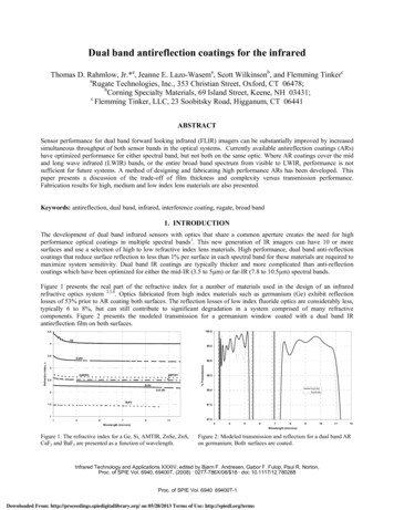
2. DESIGN APPROACH FOR DUAL BAND AR FILMSMany of the materials that are appropriate as refractive optical components for infrared applications have moderate tohigh refractive index values which give rise to high Fresnel reflection losses. A single germanium surface has areflection loss of 36%. An anti-reflection coating can reduce the optical reflection significantly over a limited spectralregion. Single band anti-reflection interference coatings of 4 to 7 layers can reduce the single surface reflection ofgermanium to less than 0.5% over a spectral range of 7.5 to 12µm. However, when transmission over multiple ranges ora broad range is required, the high performance coating design becomes more complex, and more challenging tofabricate.A contemporary approach to computer aided coating design is needle synthesis. The needle synthesis method beginswith a starting design which could be a legacy design or simply a single layer of one of the available thin film materialset. A performance target is described and a thin needle of material is systematically inserted along the thickness of thestarting design. A performance merit is calculated at each insertion point, and the thin layer is inserted at the point wherethe needle most reduces the performance merit function5. The performance merit is the root-mean-square of thedeviations between predicted performance and the performance target. The new design, now two or three layers if asingle layer starting design was used, is refined, allowing the layers to change in optical thickness so as to further reducethe merit function. The process is repeated inserting a new layer and refining the design until the insertion of any thinlayer does not reduce the merit function.Needle synthesis is a powerful method for producing designs with complex performance. However, while the methodcan produce acceptable solutions, it can just as easily produce solutions which are not easy to manufacture, or whichcontain a large number of layers and fabrication time would prohibitively drive coating cost. Understanding the designtrade-offs of film thickness, number of layers and the choice of coating materials can significantly impact coatingcomplexity and cost.2.1 Discrete Antireflection Films for ZnSeFigures 3 through 12 support the following discussion of antireflection films for zinc selenide (ZnSe) substrates. ZnSehas a medium refractive index of 2.43 in the infrared. Figure 3 presents a 5 layer discrete AR film for the far-IR region.This design reduces the reflection from 7.5 to 11µm to less than half a percent at normal and 30o angle of incidence(AOI). The impact of using this AR on ten surfaces in the system is presented in figure 4. A dual band design ofcomparable thickness and complexity is presented in figure 5. This is a 6 layer design using the same coating materialsas the single band AR presented in figure 6. The significant impact of this design on total system performance ispresented in figure 6.The film thickness, the index contrast of the selected materials and the number of layers in the design constitute thedesign space for the AR films. In order to improve the performance of the dual band AR presented in figure 5, the designspace must be extended. The challenge is to find an optimal solution which meets the performance specifications, butdoes not over tax the fabrication process. The issue is to find a practical range of film thicknesses and number of layerswhich meet the goal of less than 1% reflection in both spectral bands. A secondary issue is to seek out a set of coatingmaterials that can be used for the full range of substrate types. This allows for standardization of the fabrication processand reduced production costs. The materials used for these designs are zinc sulfide (ZnS) and yttrium fluoride (YF3) forthe medium and low index materials and germanium (Ge) for the high index material.The use of a third material in a design has the potential of expanding the design space and improving the performance ofthe film with out adding significantly to design complexity. Figures 7 and 9 present modeled performance of 2 and 3material designs. Both designs are more complex then the previous dual band design. The designs are 15 layers and aretwice as thick as the previous design. The need for improved performance drives the complexity of the design, and thistrade-off in performance versus design space is presented in figures 11 and 12 for the 2 material design set and in figures13 and 14 for the three material design set. Figure 11 plots the number of layers and the total film thickness as a functionof the optimization value of merit. The designs chosen for closer examination are those near the knee of the curve as theyare typically the best performance for the least complexity (fewest number of layers and least film thickness).Proc. of SPIE Vol. 6940 69400T-2Downloaded From: http://proceedings.spiedigitallibrary.org/ on 05/28/2013 Terms of Use: http://spiedl.org/terms
100100.099.59599.098.5% Transmission90% Transmission98.0FIT AR Ta(0.00)FIR AR 59.0Figure 3: Single Band (FIR) 5 layer discrete on ZnSe. Thefilm is 2.6 microns thick. Modeled performance at 0 and30o AOI is presented.9.510.010.511.011.512.0Wavelength (microns)Wavelength (microns)Figure 4: System Impact (10 surfaces) of the single bandFIR AR is plotted at normal and 30o AOI.100.010099.59599.098.5T Transmission% ngth (microns)89101112Wavelength (microns)Figure 5: Dual Band 6 layers discrete modeled for 0 and 30oAOI.Figure 6: System Impact (10 surfaces) for a 6 layer dualband AR of comparable thickness as the single band FIRAR.100.0100.099.595.099.090.0% Transmission% 91011123456789101112Wavelength (microns)Wavelength (microns)Figure 7: Dual Band 15 layers, 2 material discrete: 0, 30oAOI, medium/low index materialsFigure 8: System Impact (10 surfaces) for a 15 layer dualband AR.Proc. of SPIE Vol. 6940 69400T-3Downloaded From: http://proceedings.spiedigitallibrary.org/ on 05/28/2013 Terms of Use: http://spiedl.org/terms
100100.099.59599.090% Transmission% re 9: Dual Band 15 layers, 3 material discrete: 0, 30oAOI89101112Wavelength (microns)Wavelength (microns)Figure 10: System Impact (10 surfaces) for a 15 layer 3material AR modeled for 0 and 30o AOI.40100.03599.599.025# Layers% TransmissionFilm Thickness and # Layers30Film Thickness201598.58 layer Ta(0.00)15 layer Ta(0.00)27 Layer Ta(0.00)98.01097.55001234597.063Value of Merit456789101112wavelength (microns)Figure 11: Film thickness and the number of layers in the designare plotted against the optimization value of merit for a series oftwo material (ZnS/YF3) AR designs for ZnSe.Figure 12: Modeled transmission for dual band AR designs ofdifferent number of layers and thickness are compared for twomaterial AR designs for ZnSe.40100.03599.52599.0# LayersFilm Thickness% TransmissionFilm Thickness, # Layers30201598.598.024 layers Ta(0.00)15 Layers Ta(0.00)6 Layers Ta(0.00)1097.550012345697.0345Value of MeritFigure 13: Film thickness and the number of layers in the designare plotted against the optimization value of merit for a series ofthree material (ZnS/YF3) AR designs for ZnSe.678Wavelength (microns)9101112Figure 14: Modeled transmission for dual band AR designs ofdifferent number of layers and thickness are compared for threematerial AR designs for ZnSe.Figures 11 and 13 present a visualization of the trade-off between performance and design complexity. The designperformance improves with an initial increase in film thickness and the number of layers. However, the improvement infilm performance becomes increasingly small and the slope of the trend changes from nearly horizontal to nearlyvertical. The diminishing return for increased complexity is illustrates in the transmission plots of figures 12 and 14.Proc. of SPIE Vol. 6940 69400T-4Downloaded From: http://proceedings.spiedigitallibrary.org/ on 05/28/2013 Terms of Use: http://spiedl.org/terms
Table 1 presents a summary of the designs presented in figures 12 and 14. For the 2-material design, improving theperformance from 99.3% to 99.5% requires doubling the thickness of the design and nearly doubling the number of filmlayers.Table 1: Summary of Design Performance for 2 and 3 Material ZnSe Dual AR Designs;MaterialLayersThickness(µm)MeritFilm OnlyMIRTransmissionloss (1-T)Film OnlyAve FIR %TFilm OnlyFIRTransmissionloss 99.710.920.410.292.2 Dual Band AR performance by Substrate TypeUsing the design approach previously described, dual band AR film designs for Ge, AMTIR, ZnSe, ZnS, CaF2 and BaF2were developed and are presented in figures 15 through 20. Film characteristics are summarized in Table 2. All designsare in the range of 5 to 7 microns thick and 14 to 20 layers.Table 2: Summary of Predicted AR Transmission for a 1 mm Substrate Coated on Both SurfacesSubstrateTotalThickness# LayersAve ransmissionloss (1-T), 3.55µm0.731.870.970.671.433.54100Ave 7.8-10.5 µmAveTransmissionloss (1-T) 98.9398.3371.90100.095Front and BackSurface AR9090.0858080.0757070.060% Transmission% Transmission65Single Surface AR555045Uncoated 123456Wavelength (microns)7891011121314151617181920Wavelength (microns)Figure 15: Ge AR transmission is modeled on a 1 mm thickgermanium substrate. Uncoated, single surface and dual surfacecoated germanium is presented at normal and 30o AOI.Figure 16: AMTIR AR transmission is modeled for a 1 mm thickAMTIR substrateProc. of SPIE Vol. 6940 69400T-5Downloaded From: http://proceedings.spiedigitallibrary.org/ on 05/28/2013 Terms of Use: http://spiedl.org/terms
Figure 17 and 18 present the ZnSe design again, but examine the angle response of the film. Figure 17 is modeled at 0,10, 20, 30, 40, 50 and 60 o AOI. Average transmission for each spectral band is presented as a function of angle in figure18. The transmission for both bands remains flat out to the design angle of 30o and then rolls off at higher angle.Figure 20 presents an overlay of modeled performance for a dual band AR for CaF2 and BaF2. This is a plot oftransmission for only the film. CaF2 absorbs significantly above 9.5 microns and is not typically used for FIRapplications. It is included here only as a low index test substrate.1000100.0o1099.52095403099.098.5Ave Reflection% Reflection9050858098.0Ave 3.5-5Ave 7-11Ave 10203012405060AngleWavelength (microns)Figure 18: ZnSe AR average transmission in the mid and far IRbands is plotted as a function of angle.Figure 17: ZnSe AR performance for a range of angles ofincidence from normal to 60o.1001009590998580987570Film on CaF2 Ta(0.00)BaF2 Refined Ta(0.00)9760% Transmission% Transmission65555045ZnS S1S2 Ta(0.00)ZnS S1S2 8.08.59.09.510.0 10.5 11.0 11.5 12.0Wavelength (microns)Wavelength (microns)Figure 19: Figure 20: ZnS modeled transmission at 0 and 30oAOI. The 1mm substrate is modeled with the AR on bothsurfaces.Figure 21: CaF2 and BaF2 - comparison of the CaF2 Dual BandAR on CaF2 and the BaF2 AR refined for BaF2 on BaF2. Bothfilms are 13 layers. The modeled transmission is the film only.Substrate absorption is not included.Proc. of SPIE Vol. 6940 69400T-6Downloaded From: http://proceedings.spiedigitallibrary.org/ on 05/28/2013 Terms of Use: http://spiedl.org/terms
3. FABRICATION RESULTSGermanium, AMTIR, ZnSe and CaF2 were selected for test fabrication runs. Witness parts are 1” diameter and 1 mmthick, with the exception of AMTIR, which is 2mm thick. Figures 21 through 26 present measured spectral results foreach of the substrates. The selected coatings were deposited on both surfaces. Transmission and reflection measurementsinclude substrate and film absorption when present. Table 3 summarizes film performance.Table 3: Summary of Measured AR PerformanceLensMaterialGeMeasurement% T ( 0 ), % R( 10 )% T at 30 % T ( 0 ), % R( 10 )% T at 30 % T ( 0 ), % R( 10 )% T at 30 % T ( 0 ), % R( 10 )% T at 30 AMTIRZnSeCaF2Average % Transmission (loss)3.5 to 5µm7.8 to 10.5µm97.3 (2.7)96.8 (3.2)95.9 (4.1)96.3 (3.7)98.4 (1.6)97.9 (2.1)95.3 (4.7)95.8 (4.2)98.0 (2.0)97.6 (2.4)97.9 (2.1)99.0 (1.0)96.3 (3.7)89.7 (10.3)97.6 (2.4)88.6 (11.4)1001009090AR Transmission858580807575Single Surface ARTransmission7065606055Ge Uncoated50Single surface AR transmission7065% Transmission%T, %RAR Transmission95954540Uncoated 0.54.55.56.511.07.58.59.510.5Wavelength (microns)Wavelength (microns)Figure 22: Measured transmission and reflection for the Ge3-material design on both surfaces of a 1 mm thick witness part.Figure 23: Measured transmission for the AMTIR3-material design on both surfaces of a 2 mm thick witness part.100.00100.00AR Transmission95.0090.00Single surface AR ZnSe65.00% T, %R%T, 50Reflection5.00Reflection5.000.003.50Single Surface AR Transmission85.0080.0070.00AR ngth (microns)Wavelength (microns)Figure 24: Measured transmission and reflection for the ZnSe2-material design on both surfaces of a 1 mm thick ZnSe witnesspart.Figure 25: Measured transmission and reflection for the ZnSe3-material design on both surfaces of a 1 mm thick ZnSe witnesspart.Proc. of SPIE Vol. 6940 69400T-7Downloaded From: http://proceedings.spiedigitallibrary.org/ on 05/28/2013 Terms of Use: http://spiedl.org/terms
100.00AR TransmissionSingle surface AR Transmission95.00% TransmissionUncoated 50Wavelength (microns)Figure 26 : Measured transmission for the CaF2 2-materialdesign on both surfaces of a 1 mm thick CaF2 witness part.4. CONCLUSIONSHigh performance dual band AR coatings are more complex and thicker than single band AR coatings, but performancein both bands can be designed and fabricated to performance levels comparable to single band AR coatings. A commonset of coating materials can be used to cover lens materials with very different refractive index values. The fabricatedfilms exhibit good spectral performance and cosmetic quality. The goal of less than 1% reflection in the both bands is apractical specification.REFERENCES[1] Hall, J., “Army Applications for Multi-Spectral Windows”, Proc. SPIE 3060, 330-334 (1997).[2] Palik, E. D., [Handbook of Optical Constants in Solids], Academic Press (1985).[3] Hilton, Sr., A.R., “Precise refractive index measurements of infrared materials”, Proc. SPIE 1307, 516-521 (1990).[4] “GASIR 3 – Infrared transmitting glass”, Umicore Electro-Optical Materials’ Product Literature, www.optics.umicore.com[5] “Advanced Thin-Film Optical Coatings; Evaluation and Design”, OptiLayer Ltd., Product literature (1998).[6] Rahmlow, T. D., Lazo-Wasem, J. E., Gratrix, E. J., “Narrow band infrared filters with broad field of view”, Proc. SPIE 6206,62062S-1 – 62062S-8 (2006).[7] Vizgaitis, J., “Dual f/number optics for 3rd generation FLIR systems”, Proc. SPIE 5783, 875-886 (2005).[8] Norton, P., Campbell, J., Horn, S., Reago, D., “Third-generation imagers”, Proc. SPIE 4130, 226-236 (2000).[9] Harris, D, [Materials for Infrared Windows and Domes], SPIE Optical Engineering Press (1999).[10] Hawkins, G., Hunneman, R., “The temperature dependent spectral properties of filter substrate materials in the far-infrared (6-40µ)”, Infrared Physics and Technology 45,69-79, Elsevier (2004).Proc. of SPIE Vol. 6940 69400T-8Downloaded From: http://proceedings.spiedigitallibrary.org/ on 05/28/2013 Terms of Use: http://spiedl.org/terms
The development of dual band infrared sensors with optics that share a common aperture creates the need for high performance optical coatings in multiple spectral bands1. This new generation of IR imagers can have 10 or more surfaces and use a selection of high to low refractive index lens materials. High performa nce, dual band anti-reflection