Transcription
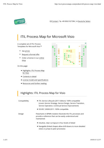
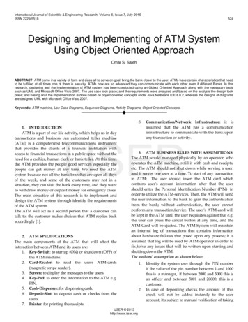
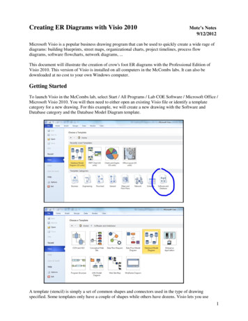
Creating ER Diagrams with Visio 2010Mote’s Notes9/12/2012Microsoft Visio is a popular business drawing program that can be used to quickly create a wide rage ofdiagrams: building blueprints, street maps, organizational charts, project timelines, process flowdiagrams, software flowcharts, network diagrams, .This document will illustrate the creation of crow's foot ER diagrams with the Professional Edition ofVisio 2010. This version of Visio is installed on all computers in the McCombs labs. It can also bedownloaded at no cost to your own Windows computer.Getting StartedTo launch Visio in the McCombs lab, select Start / All Programs / Lab COE Software / Microsoft Office /Microsoft Visio 2010. You will then need to either open an existing Visio file or identify a templatecategory for a new drawing. For this example, we will create a new drawing with the Software andDatabase category and the Database Model Diagram template.A template (stencil) is simply a set of common shapes and connectors used in the type of drawingspecified. Some templates only have a couple of shapes while others have dozens. Visio lets you use1
multiple templates on the same drawing if necessary. Only one template will be necessary to draw our ERdiagrams.Visio will then give you a blank worksheet (like graph paper) and the template containing the basicshapes and connectors for the chosen drawing type. Most crow's foot ER diagrams can be created withjust two of the seven basic database shapes and connectors: entity and relationship.2
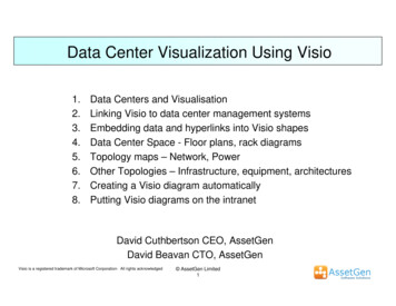
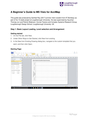
If your initial worksheet appears in the portrait orientation, you might want to rotate it to landscapeorientation to make more effective use of your rectangular screen. To do this, select the Page Setup optionfrom the Design menu tab.In addition to the worksheet orientation, Page Setup allows you to change the scaling, paper size, margins,layout and routing behavior, etc.3
EntitiesBegin creating your ER diagram by dragging the Entity (table) shape from the template to the worksheet.You can reposition it at any time. You can delete any shape by selecting it and pressing the delete key.If the drawing is too small to view, you can zoom in with the slider control in the bottom right corner ofthe Visio window. This doesn't change the actual size of the drawing when you print it; it simply allowsyou to have a close up view when you are working on it.4
Click the entity to view/edit its name, columns, primary key, secondary indices, etc.Change the default name (Table1) of the entity to its proper name (e.g., tblParent). Visio allows you tospecify different physical and conceptual names for each entity. Since the Sync Name property has beenselected, you only need to enter one new name for the table.5
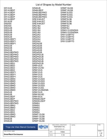
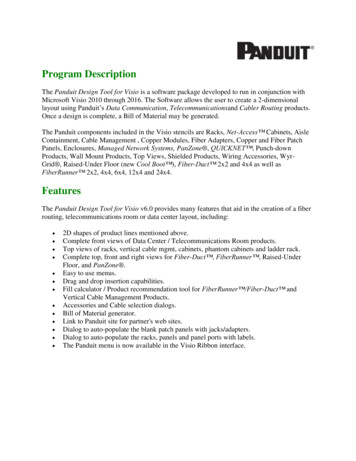
Switch to the Columns (fields) category of properties. Enter the names of the fields.Visio automatically assigns a default data type/size of ten character text to all new columns. If desired,you can change the columns to their proper data types and sizes.Indicate the appropriate Required and Primary Key (PK) properties for each field. Notice that Visioautomatically underlines the SSN key field and moves it to the top of the diagram. We will change thisfield shuffling behavior later.6
The three required fields of the table are shown in boldface and the two optional fields are shown instandard face.You can change the font size by selecting the entity then picking a size from the Home menu tab. You canalso change the font family, color, alignment, etc.7
RelationshipsFollow the same basic steps to create a second table. Notice that the tblChild table in this example has twosocial security number fields. SSN is the ID for the child and MotherSSN is the ID for the child's mother.MotherSSN will be a foreign key (pointer) to tblParent.Drag the Relationship connector from the template to a blank space in your worksheet. By default,relationships appear as simple arrows. We will change to the crow's foot style later.8
Click the end of the relationship connector with the arrowhead. Drag it over tblParent until the borderturns red.Drag the other end of the relationship connector over tblChild until it turns red.It is very important that you connect the tables in the proper direction. The arrowhead must be on the oneside (i.e., parent-side) and the tail must be on the many-side (i.e., child-side) of the relationship.Remember: In Codd's relational database model, children point to their parents. Parents do not point totheir children.It takes a sharp eye to realize that something has gone wrong. Do you see it?When the relationship was created between tblParent and tblChild, Visio assumed SSN was to be used asthe matching field in both tables. Unfortunately, that assumption is only half right. SSN in tblParent issupposed to match MotherSSN in tblChild. To correct this foreign key mistake, click the relationship.9
Highlight SSN in tblParent and MotherSSN in tblChild, then click the Associate button.Now MotherSSN correctly appears as a foreign key that links each child record to its parent.10
Fine-tuning the DrawingMany of the basic drawing style options can be accessed from Display Options in the Database menu tab.The General tab lets you select the IDEF1X or Relational symbols. It also lets you select which set ofentity names to display.The Table tab lets you select the items to display (e.g., PK, FK, secondary indices, non-key fields, datatypes). You can also elect to display the primary key fields at the top of each entity or in their actualphysical order.Select the Physical Order option in order to have the two SSN fields displayed in their original (third)positions instead of at the top of tblParent and tblChild above the horizontal lines.11
The Relationship tab lets you display the relationships as arrows or as crow's feet.Select the Crow's Feet option. Notice that the mother-child relationship is shown as mandatory on theone-side and optional on the many-side. We will see how to change this later.Create a new FatherSSN field in tblChild, then create a one-to-many relationship between SSN andFatherSSN.12
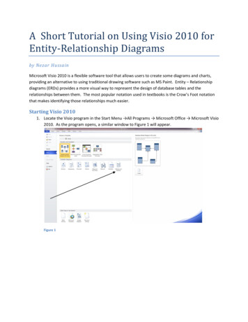
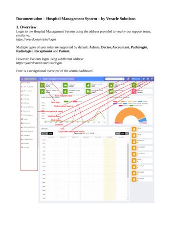
This illustrates one of the problems encountered with more complex ER diagrams. In particular, ourdrawing has two parallel relationships that appear identical. We know that one represents the motherchild relationship and the other represents the father-child relationship, but the difference isn't particularlyclear in the simple diagram.Visio offers a solution. It lets you add simple labels to individual relationships. To do this, click arelationship, then enter a descriptive name. In order to minimize unnecessary clutter in your drawing, youmight want to use short relationship labels like Mom and Dad.Open the Display Options from the Database menu tab, then select the Show Physical Name option fromthe Relationship tab.13
Now the Mom and Dad labels appear on the appropriate relationships.By default, the one-to-many relationships were created as mandatory on the one-side and optional on themany-side. You can change this on a case-by-case basis by clicking the appropriate relationship. Forinstance, you can force every tblParent record to have at least one child by changing the motherrelationship to One or More cardinality. You can force every parent to have between two and fivechildren by selecting the Range cardinality then specifying the At Least and At Most frequencies.14
Initially, the mother and father relationships were defined as mandatory on the one-side becauseMotherSSN and FatherSSN were defined as required fields. If you want to allow a child to not have afather, then de-select the Req'd checkbox for FatherSSN. Now the relationship is optional in bothdirections.Wrapping UpSelect Save or Save As from the File menu tab when you are finished with your ER diagram. Note thatVisio will use VSD as the extension for all drawing files.If you wish, you can also save your drawing as a PDF, JPG, GIF, etc. Of course, you cannot edit thesenon-VSD files at a later point, but they can be handy if you want to print your drawing on a computer thatdoes not have Visio.15
To launch Visio in the McCombs lab, select Start / All Programs / Lab COE Software / Microsoft Office / Microsoft Visio 2010. You will then need to either open an existing Visio file or identify a template category for a new drawing. For this example, we will create a new drawing with the Software and Database category and the Database Model .