Transcription
Dell EMC Networking OS10 Enterprise EditionSwitch Configuration Guide for VxRail 4.5Deploying a pair of S5148F-ON switches for a VxRail 4.5 clusterAbstractThis document provides Dell EMC Networking OS10 Enterprise Editionswitch configuration examples and topology options for a VxRail 4.5cluster deployment.March 2019Dell EMC Configuration and Deployment Guide
RevisionsRevisionsDateDescriptionMarch 2019Changed switch node-facing interface settings from “flowcontrol transmit on” to“flowcontrol transmit off” as a best practice.September 2018Initial releaseThe information in this publication is provided “as is.” Dell Inc. makes no representations or warranties of any kind with respect to the information in thispublication, and specifically disclaims implied warranties of merchantability or fitness for a particular purpose.Use, copying, and distribution of any software described in this publication requires an applicable software license. 2018 Dell Inc. or its subsidiaries. All Rights Reserved. Dell, EMC, Dell EMC and other trademarks are trademarks of Dell Inc. or its subsidiaries. Othertrademarks may be trademarks of their respective owners.Dell believes the information in this document is accurate as of its publication date. The information is subject to change without notice.2Dell EMC Networking OS10 Enterprise Edition Switch Configuration Guide for VxRail 4.5
RevisionsTable of contentsRevisions.212Introduction .51.1Supported switches and operating systems .61.2Typographical conventions .71.3Attachments .7Hardware overview .82.1Dell EMC Networking S5148F-ON .82.2Dell EMC Networking S3048-ON .82.3Dell EMC VxRail 14G nodes .82.3.1 Dell EMC VxRail P Series node .82.3.2 Dell EMC VxRail V Series node .92.3.3 Dell EMC VxRail S Series node .92.3.4 Dell EMC VxRail E Series node .92.3.5 VxRail node network adapters.93Topology options .113.1Dual switch .113.1.1 Dual switch with VLT .113.1.2 Dual switch without VLT .123.24567Single switch .13VxRail in the data center .144.1Leaf-spine network .144.2OOB management network .15Configuration planning .165.1VLANs and IP addresses .165.2VxRail network configuration table .175.3Using a jump box or laptop computer .185.4DNS and NTP servers .18Switch configuration prerequisites.206.1Check switch OS version.206.2Verify license installation .206.3Factory default configuration .21Configure switches .227.1Dual switch with VLT .227.1.1 General settings.227.1.2 Configure VLANs .233Dell EMC Networking OS10 Enterprise Edition Switch Configuration Guide for VxRail 4.5
Revisions7.1.3 Configure interfaces .247.1.4 Configure VLT.257.2Dual switch without VLT .267.2.1 General settings.267.2.2 Configure VLANs .277.2.3 Configure interfaces .287.2.4 Configure the switch interconnect .297.3Single switch .307.3.1 General settings.317.3.2 Configure VLANs .317.3.3 Configure interfaces .328Switch validation .358.1General validation commands .358.1.1 show interface status .358.1.2 show port-channel summary .358.1.3 show vlan .368.1.4 show lldp neighbors .378.1.5 show vrrp brief .388.2VLT validation commands .388.2.1 show vlt domain id .388.2.2 show vlt domain id backup-link .388.2.3 show vlt domain id mismatch.3949Deploy VxRail .40AValidated components .41A.1Dell EMC Networking Switches .41A.2VxRail P570 nodes .41A.3VxRail Appliance software .42BVxRail network adapter traffic optimization .43CTechnical resources .44DSupport and feedback .45Dell EMC Networking OS10 Enterprise Edition Switch Configuration Guide for VxRail 4.5
Introduction1IntroductionVxRail sits at the forefront of a fundamental shift in IT infrastructure consumption – away from applicationspecific, “build-your-own” infrastructure and toward virtualized, general-purpose, engineered systems. DellEMC and VMware have embraced this shift with the VxRail hyper-converged appliance. VxRail has a simple,scale-out architecture that leverages VMware vSphere and VMware vSAN to provide server virtualization andsoftware-defined storage.To take full advantage of the VxRail solution, one must carefully consider the network that not only connectsmultiple nodes into a single, cohesive cluster but also enables connectivity to the customer’s IT environment.Numerous industry studies have shown that networking is the primary source of both deployment issues andpoor performance of hyper-converged solutions. In most cases, VxRail clusters (minimum of three andmaximum of 64 nodes) connect to a pre-existing IP network at the customer site. The inclusion of dedicatedswitches for the VxRail cluster simplifies this process and avoids many of the pitfalls associated with thedeployment of a hyper-converged solution that originates in network connectivity.The audience for this document includes professional services or onsite IT personnel responsible for thedeployment of a VxRail cluster when a pair of dedicated Dell EMC Networking switches is purchased with thecluster. This document covers the process of connecting a cluster of VxRail nodes to: A pair of Dell Networking switches configured for Virtual Link Trunking (VLT). Using VLT is thepreferred topology.A pair of Dell Networking switches not configured for VLT.A single Dell Networking switch.This document provides switch topology options and configuration examples for a VxRail 4.5 cluster usingnodes built on 14th generation (14G) PowerEdge servers. Nodes in these examples use 25GbE networkadapters. Switches in this guide use Dell EMC Networking OS10 Enterprise Edition (OS10EE).5Dell EMC Networking OS10 Enterprise Edition Switch Configuration Guide for VxRail 4.5
Introduction1.1Supported switches and operating systemsThe examples provided in this deployment guide use VxRail 4.5 nodes connected to Dell EMC NetworkingS5148F-ON switches running Dell Networking OS10EE.Dell EMC Networking supports the following switch and OS combinations for VxRail 4.0 and later:Supported Dell EMC Networking switches and operating systems6Dell EMC Networking OS10 Enterprise Edition Switch Configuration Guide for VxRail 4.5
Introduction1.2Typographical conventionsThe CLI and GUI examples in this document use the following conventions:1.3Monospace TextCLI examplesUnderlined Monospace TextCLI examples that wrap the pageItalic Monospace TextVariables in CLI examplesBold Monospace TextCommands entered at the CLI prompt, or to highlight information in CLIoutputBold textGUI fields and information entered in the GUIAttachmentsThis document in .pdf format includes switch configuration file attachments. To access attachments in AdobeAcrobat Reader, click the icon in the left pane halfway down the page, then click theicon.7Dell EMC Networking OS10 Enterprise Edition Switch Configuration Guide for VxRail 4.5
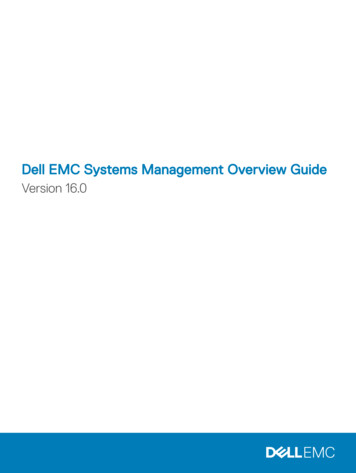
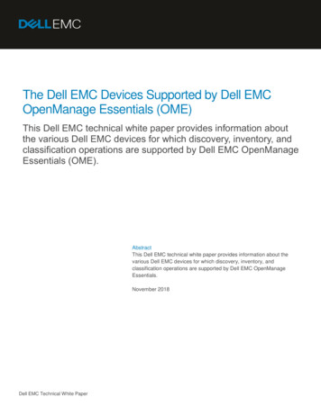
Hardware overview2Hardware overviewThis section briefly describes the hardware used to validate this deployment. Appendix A contains a completelisting of hardware and software validated for this guide.2.1Dell EMC Networking S5148F-ONThe S5148F-ON is a 1-Rack Unit (RU), multilayer switch with 48x25GbE, and 6x100GbE or 72x25GbE ports.This guide uses two S5148F-ONs as leaf switches.Dell EMC Networking S5148F-ON2.2Dell EMC Networking S3048-ONThe S3048-ON is a 1-RU switch with 48x1GbE BASE-T ports and 4x10GbE SFP ports. This guide uses oneS3048-ON switch for out-of-band (OOB) management traffic.Dell EMC Networking S3048-ON2.3Dell EMC VxRail 14G nodesCurrent Dell EMC VxRail P, V, S, and E Series nodes are built on 14th generation (14G) PowerEdge servers.2.3.1Dell EMC VxRail P Series nodeVxRail P Series nodes are ideal for CPU-intensive workloads such as databases. P Series nodes support upto 44 CPU cores, 1536GB memory, and 24TB hybrid or 46TB all-flash storage in a 2-RU form factor.Dell EMC VxRail 2-RU node (P, V, or S Series)Note: The deployment examples in this guide use a VxRail cluster consisting of four P570 nodes.8Dell EMC Networking OS10 Enterprise Edition Switch Configuration Guide for VxRail 4.5
Hardware overview2.3.2Dell EMC VxRail V Series nodeVxRail V Series nodes are graphics-ready for uses such as high-end 2D/3D visualization. V Series nodessupport up to 40 CPU cores, 1024GB memory, 3 GPUs, and 24TB hybrid or 46TB all-flash storage in a 2-RUform factor.2.3.3Dell EMC VxRail S Series nodeVxRail S Series nodes provide expanded storage capacity for collaboration, data, and analytics. S Seriesnodes support up to 36 CPU cores, 1536GB memory, and 48TB hybrid storage in a 2-RU form factor.2.3.4Dell EMC VxRail E Series nodeVxRail E Series nodes are best suited for remote office or entry workloads. E Series nodes support up to 40CPU cores, 1536GB memory, and 16TB hybrid or 30TB all-flash storage in a 1-RU form factor.Dell EMC VxRail E Series node2.3.5VxRail node network adaptersEach 14G VxRail node includes a rack server Network Daughter Card (rNDC) with one of the following portcombinations: 2x25GbE SFP28 ports2x10GbE SFP or BASE-T ports4x10GbE SFP or BASE-T ports4x1GbE BASE-T ports (for single CPU nodes only, max 8 nodes/cluster)Rear view of VxRail 2-RU node (1-RU node is similar)Note: Each of the VxRail P570 nodes in the deployment examples in this guide contains a Broadcom 57414rNDC with 2x25GbE SFP28 ports.VxRail optimizes network traffic by splitting it across rNDC uplinks and by using Network I/O control (NIOC)shares for different traffic types. See Appendix B for more information.9Dell EMC Networking OS10 Enterprise Edition Switch Configuration Guide for VxRail 4.5
Hardware overviewP, V, S, and E Series VxRail nodes also include a 1GbE BASE-T integrated Dell Remote Access Card(iDRAC) for OOB management.Note: P, V, and S Series nodes support additional network adapters in PCIe slots. See the Dell EMC VxRailNetwork Guide for more information.10Dell EMC Networking OS10 Enterprise Edition Switch Configuration Guide for VxRail 4.5
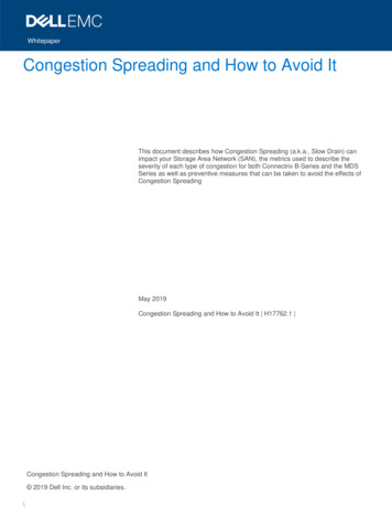
Topology options3Topology optionsVxRail may be deployed using a single or dual switch topology. Using a single switch provides the lowestinitial cost, but creates a single point of failure. A dual switch configuration helps ensure high availability byeliminating this single point of failure.A dual switch configuration may be used with or without VLT. Dell EMC recommends a dual switchconfiguration with VLT. The sections that follow explain the different options.3.1Dual switchIn a dual switch topology, each VxRail node has one or more connections to each of the two leaf switchesproviding redundancy at the NIC and switch levels. If VLT is used, the switches are connected with a VLTinterconnect (VLTi). If VLT is not used, the switches are connected with a standard LACP port channel.3.1.1Dual switch with VLTDell EMC recommends using a dual switch configuration with VLT as shown in Figure 7.S5148F-Leaf1AS5148F-Leaf1BVLTi1 2VxRail node 1100GbE VLTi connections25GbE connections1 2VxRail node 21 2VxRail node nRack 1Dual switch topology with VLTVLT synchronizes ARP, MAC tables, and IPv6 neighbors between the VLT peers and makes the switch pairappear as one logical unit to connected devices.VLT provides the following benefits: 11Provides a loop-free topology and eliminates STP-blocked portsOptimizes the use of all available uplink bandwidthGuarantees fast convergence if either a link or a device failsDell EMC Networking OS10 Enterprise Edition Switch Configuration Guide for VxRail 4.5
Topology options Provides link-level resiliencyAssures high availabilityAllows a single device to use a LAG across two upstream switchesProvides Layer 2 multipathingNote: While VxRail nodes use active and standby network adapters instead of LAGs, other servers in therack can connect to the VLT switch pair with an LACP LAG for active/active Layer 2 multipathing. For moreinformation on VLT, see the OS10 Enterprise Edition User Guide Release 10.4.1.0.3.1.2Dual switch without VLTThe configuration of a switch pair without VLT is supported, but it does not provide the advantages of VLTcovered in the previous section.The switch pair is cabled as shown in Figure 8. The links connecting the two switches are configured in anLACP port channel.S5148F-Leaf1BS5148F-Leaf1ALACP1 2VxRail node 11 2100GbE LACP connections25GbE connectionsVxRail node 21 2VxRail node nRack 1Dual switch topology without VLT12Dell EMC Networking OS10 Enterprise Edition Switch Configuration Guide for VxRail 4.5
Topology options3.2Single switchIn a single switch topology, all VxRail nodes connect to a single switch. This topology is lower initial cost, butit is not recommended as the switch becomes a single point of failure.S5148F-ON1 2VxRail node 11 225GbE connectionsVxRail node 21 2VxRail node nRack 1Single switch topology13Dell EMC Networking OS10 Enterprise Edition Switch Configuration Guide for VxRail 4.5
VxRail in the data center4VxRail in the data center4.1Leaf-spine networkDell EMC recommends using a leaf-spine network in the data center with leaf switches configured as VLTpeers. The switches and VxRail nodes covered in this guide are shown in Rack 1 in Figure 10 and areincorporated into a data center’s leaf-spine al VxRail clusters, servers,storage, etc.Additional VxRail clusters, servers,storage, etc.Rack 2Rack nL2VxRail node 1VxRail node 2VxRail node nRack 1Leaf-spine connectionsVLTi connectionsDevice connectionsLayer 2/Layer 3 boundaryDual switch topology with VLT connected to a leaf-spine networkIn Figure 10, the Layer 2/Layer 3 boundary is at the leafs, meaning traffic within each rack is switched (Layer2) and traffic between racks is routed (Layer 3). VMware Validated Design 4.3, Architecture and Designrecommends isolating vSAN traffic to its own Layer 2 network segment. Therefore, for this leaf-spinetopology, each vSAN should be contained within a single rack. Since a VxRail cluster contains a vSAN, aVxRail cluster is also contained within a single rack.Note: By default, VxRail does not enable routing of vSAN or vMotion traffic.The leaf-spine topology in Figure 10 scales to sixteen racks or more, depending on the number of portsavailable in each spine. Racks may contain additional VxRail clusters, switches, servers, storage arrays, andother devices as needed.To configure the remainder of the leaf-spine network, including spine switches, connections between leafsand spines, and routing protocols, see the Dell EMC Networking Layer 3 Leaf-Spine Deployment and BestPractices with OS10EE.14Dell EMC Networking OS10 Enterprise Edition Switch Configuration Guide for VxRail 4.5
VxRail in the data center4.2OOB management networkThe out-of-band (OOB) management network is an isolated network for remote management of servers,switches, and storage devices via their dedicated hardware management ports. It is also commonly used tocarry heartbeat messages sent between switches configured as VLT peers.For OOB management connections, one S3048-ON switch is installed in each rack as shown:OOBManagementNetworkRack 1Rack 2Rack 3Rack nS3048-ONS3048-ONS3048-ONS3048-ONLeaf Switch 1ALeaf Switch 2ALeaf Switch 3ALeaf Switch nALeaf Switch 1BLeaf Switch 2BLeaf Switch 3BLeaf Switch nBVxRail NodeCluster 1VxRail NodeCluster 1VxRail NodeCluster 1VxRail NodeCluster 1VxRail NodeCluster 2VxRail NodeCluster 2VxRail NodeCluster 2VxRail NodeCluster 2VxRail NodeCluster 3VxRail NodeCluster 3VxRail NodeCluster 3PowerEdgeServerSpine Switch 1Spine Switch 2PowerEdgeServerStorage ArrayOOB management network connectionsNote: This guide focuses on the devices in Rack 1. Devices shown in other racks are for illustration only.1GbE BASE-T ports on each S3048-ON are connected downstream to hardware management ports on eachdevice. This includes VxRail node iDRACs, PowerEdge Server iDRACs, and dedicated management ports onswitches and storage arrays.Four 10GbE SFP ports are available on each S3048-ON for use as uplinks to the OOB managementnetwork core.Note: This is not to be confused with the in-band management network which runs on the same physicalnetwork as other VxRail and end-user traffic. In-band connections are covered in Section 3.Devices on the OOB management network in this guide use the 100.67.0.0/16 IP address block.15Dell EMC Networking OS10 Enterprise Edition Switch Configuration Guide for VxRail 4.5
Configuration planning5Configuration planning5.1VLANs and IP addressesVLANs and IP addresses used for VxRail node traffic must be planned before switch configuration and VxRaildeployment can begin.VxRail node traffic is divided into four or more VLANs as shown in Table 1.VLANs used for VxRail nodesVLANPurposeManagementSingle VLAN for in-band management traffic used for VxRail node-to-node, ESXihost management, vCenter server, NTP, DNS, and VxRail management trafficvMotionSingle VLAN for virtual machine (VM) migrationvSANSingle VLAN for vSAN storage trafficVM Network(s)One or more VLANs for VM data trafficVLAN configuration and IP network addresses planned for this deployment are shown in Table 2.VLANs and IP addressesVLAN ID DescriptionNetworkGatewayVLAN Traffic1611In-Band NATagged1614VM Network A172.16.14.0/24Optional, not usedTagged1615VM Network B172.16.15.0/24Optional, not usedTaggedNote: By default, VxRail does not enable routing of vSAN or vMotion traffic.This example uses two networks for VM data traffic, VM Network A and VM Network B, with each on aseparate VLAN. The actual number of VM data networks used is based on customer requirements.16Dell EMC Networking OS10 Enterprise Edition Switch Configuration Guide for VxRail 4.5
Configuration planning5.2VxRail network configuration tableInformation provided in the VxRail network configuration table is used during VxRail deployment. The valuesused for this deployment example are shown in the right column. The VLANs and IP addresses used arebased on the information from Table 2.Note: For additional information on the VxRail network configuration table, see the Dell EMC VxRail NetworkGuide.VxRail network configuration tableRow1VxRail23SystemCategoryDescriptionValues usedManagementVLAN IDThe recommended is untagged traffic on the Native VLAN. Ifyou want the host to send only tagged frames, manuallyconfigure the VLAN on each ESXi host using DCUI, andset tagging for your management VLAN on your switchbefore you deploy VxRail.1611 (untagged)VxRail initial IPIf you cannot reach the default (192.168.10.200/24), set analternate IP address192.168.10.200Global settingsTime zone4NTP server(s)172.16.11.505DNS server(s)172.16.11.506Proxy settings78Username and passwordManagementESXi hostname prefixvxhostSeparatornoneIteratorNum 0x11Offset112Suffixnone13Domaindell.local14ESXi starting address for IP pool172.16.11.115ESXi ending address for IP pool172.16.11.40vCenter ServerLeave blank ifCustomerSupplied VCvCenter Server hostnamevxvcentervCenter Server IP addressPlatform Services Controller hostname172.16.11.100vxpscPlatform Services Controller IP address172.16.11.101CustomerSuppliedvCenter ServerLeave blank ifVxRail VCCustomer Supplied Platform ServicesController (PSC) Hostname (FQDN) Leave9101617181920212223ESXihostnames andIP addressesCustomer Supplied vCenter Server hostname (FQDN)Customer Supplied vCenter Server SSO domainadmin username/password or the newly created VxRail nonadmin username and password24New VxRail management username and password25Customer Supplied data center name26New cluster name27VxRail Manager2829Networking3031Passwords323317IP address and portvMotionVxRail hostnamevxmanVxRail IP address172.16.11.102Subnet mask255.255.255.0GatewayESXi “root” passwords. Can be different for each host startingwith Release 4.0.100.VxRail Manager and VxRail vCenter 54Dell!234P3ll!234Starting address for IP pool172.16.12.134Ending address for IP pool172.16.12.4035Subnet mask255.255.255.0Dell EMC Networking OS10 Enterprise Edition Switch Configuration Guide for VxRail 4.5
Configuration planningRowCategoryDescriptionValues usedVLAN ID1612Starting address for IP pool172.16.13.138Ending address for IP pool172.16.13.4039Subnet mask255.255.255.040VLAN ID1613VM Network name and VLAN IDVM Network A, 1614VM Network name and VLAN IDvRealize Log Insight hostnameVM Network B, 1615vxinsight44vRealize Log Insight IP address172.16.11.10345Syslog server (instead of Log Insight)3637414243vSANVMNetworks (unlimitednumber)SolutionsLoggingThis deployment uses four VxRail nodes. However, host IP address pools are configured for theManagement, vMotion, and vSAN VLANs using addresses in the .1 - .40 range in Table 3. This ensures IPaddresses are preconfigured for hosts that may be added later as the VxRail cluster grows.5.3Using a jump box or laptop computerFor VxRail deployment, VxRail Manager is accessed via the leaf switches connected to the nodes. This maybe done by connecting a laptop computer directly to a leaf or by using a jump box (also known as a jumpserver or jump host) for remote access.Reserve at least one interface on a leaf switch for this connection. This interface is configured on the in-bandmanagement VLAN during switch configuration.Note: A PowerEdge server is used as a jump box in this deployment. More
Dell EMC Configuration and Deployment Guide . Dell EMC Networking OS10 Enterprise Edition Switch Configuration Guide for VxRail 4.5 . Deploying a pair of S5148F-ON switches for a VxRail 4.5 cluster . Abstract . This document provides Dell EMC Networking OS10 Enterprise Edition switch configuration examples and topology options for a VxRail 4.5