Transcription
PERC H200.book Page 1 Tuesday, July 13, 2010 4:15 PMDell PowerEdge RAIDController (PERC) H200 and6Gbps SAS HBAUser’s Guide
PERC H200.book Page 2 Tuesday, July 13, 2010 4:15 PMNotes, Cautions, and WarningsNOTE: A NOTE indicates important information that helps you make better use ofyour computer.CAUTION: A CAUTION indicates potential damage to hardware or loss of data ifinstructions are not followed.WARNING: A WARNING indicates a potential for property damage, personalinjury, or death.Information in this publication is subject to change without notice. 2009-2010 Dell Inc. All rights reserved.Reproduction of these materials in any manner whatsoever without the written permission of Dell Inc.is strictly forbidden.Trademarks used in this text: Dell, the DELL logo, PowerEdge, and OpenManage are trademarks ofDell Inc.; Microsoft, Windows and Windows Server are either trademarks or registered trademarks ofMicrosoft Corporation in the United States and/or other countries; Novell, NetWare, and SUSE areregistered trademarks of Novell, Inc. in the United States and other countries; Red Hat and Red HatEnterprise Linux are registered trademarks of Red Hat Inc.in the United States and other countries.Other trademarks and trade names may be used in this document to refer to either the entities claimingthe marks and names or their products. Dell Inc. disclaims any proprietary interest in trademarks andtrade names other than its own.UCS-71, UCS-70, and UCSM-70July 2010Rev. A01
PERC H200.book Page 3 Tuesday, July 13, 2010 4:15 PMContents1CAUTION: Safety Instructions .SAFETY: General. . . . . . . . .9. . . . . . . . . . . . . . . . . . .9SAFETY: When Working Inside Your System. . . . . .10Protecting Against Electrostatic Discharge. . . . . .10. . . . . . . . . . . . . . . .11. . . . . . . . . . . . . . . . . . . . . . . . .13SAFETY: Battery Disposal2OverviewOperating System Support .About RAID .3. . . . . . . . . . . . . . .14. . . . . . . . . . . . . . . . . . . . . . .15RAID Levels . . . . . . . . . . . . . . . . . . . .15RAID Terminology. . . . . . . . . . . . . . . . . . . .15RAID 0 . . . . . . . . . . . . . . . . . . . . . . .15RAID 1 . . . . . . . . . . . . . . . . . . . . . . .16RAID 10. . . . . . . . . . . . . . . . . . . . . . .17PERC H200 and 6Gbps SASHBA Features . . . . . . . . . . . . . . . . . . . .LED Port Activity Feature for 6GbpsSAS HBA Only . . . . . . . . . . . . . . . . . . . . .22. . . . . . . . . . . . . . .23. . . . . . . . . . . . . . . .23Physical Disk Cache PolicyUnsupported Drives19Contents3
PERC H200.book Page 4 Tuesday, July 13, 2010 4:15 PM4Hardware Installation. . . . . . . . . . . . . .Installing the PERC H200 and 6GbpsSAS HBA Cards. . . . . . . . . . . . . . . . . . . . .Installing the PERC H200 Modular Card .5Driver Installation. . . . . . . . . . . . . . . . . . . . . . . .2831. . . . . . . . . . . . .32Creating the Driver Media. . . . . . . . . . . . .32. . . . . . . . . . .32Installing the Driver During a WindowsServer 2003 Operating System Installation . . . .33Installing the Driver During a Windows Server2008 or Windows Server 2008 R2 Installation . .34Installing a Windows Server 2003, WindowsServer 2008 or Windows Server 2008 R2 Driverfor a New RAID Controller . . . . . . . . . . . .35. . . . . . . . . . .36. . . . . . . . . . . . . . . . .37. . . . . . . . . . . . . . . . . . .37. . . . . . . . . . . . . .39Updating the Windows DriverInstalling Linux Driver .Creating a DUDCreating a DUD Using DKMSInstalling Red Hat Enterprise Linux OperatingSystem Using the DUD . . . . . . . . . . . . . .39. . . . . .40. . . . . . . . .40. . . . . . . . . . . . . . .41Installing SUSE Linux Enterprise ServerUsing the DUD . . . . . . . . . . . . .Installing the RPM Package WithDKMS Support . . . . . . . . . .Upgrading the Kernel .Contents25Installing the Windows Driver .Pre-Installation Requirements425
PERC H200.book Page 5 Tuesday, July 13, 2010 4:15 PM6PERC H200 and 6Gbps SASHBA BIOS . . . . . . . . . . . . .POST Messages. . . . . . . . . . .43. . . . . . . . . . . . . . . . . . . . .43. . . . . . . . . . . .43. . . . . . . . .44. . . . . . . . . . . . . . . . . .44BIOS Fault Code MessagesBooting With Multiple ControllersConfiguration Utility .Starting the Configuration Utility .Functions Performed. . . . . . . . .44. . . . . . . . . . . . . . . .44RAID Configuration and Management Screens .Select New Volume Type .46. . . . . . . . . . . . .47. . . . . . . . . . . . . . . .47. . . . . . . . . . . . . . . . . . . .50. . . . . . . . . . . . . . . . . .50. . . . . . . . . . . . . . . . . . . . .51Create New VolumeView VolumeManage VolumeExit Screen. . . .Performing Configuration Tasks . . . . . . . . . . . .51Creating a RAID 0 Virtual Disk. . . . . . . . . . .52Creating a RAID 1 Virtual Disk. . . . . . . . . . .53Creating a RAID 10 Virtual Disk . . . . . . . . . .54Viewing Virtual Disk Properties. . . . . . . . . .55. . . . . . . . . . . . . .56. . . . . .57. . . . . . . . . . . . . . .57. . . . . . . . . . . . . . . . .57Activating a Virtual DiskMigrating and Activating a Virtual DiskDeleting a Virtual DiskHot Spare FailoverReplacing and Rebuilding aDegraded Virtual Disk . . . . . . . . . . . . . .58. . . . . . . .58Assigning a Preferred Boot DeviceContents5
PERC H200.book Page 6 Tuesday, July 13, 2010 4:15 PM7Troubleshooting .BIOS Boot Order. . . . . . . . . . . . . . . . . . . . . . . . . . . . . . . . . . . . . .Background Activities .General Issues61. . . . . . . . . . . . . . . . . . . . . .61. . . . . . . . . . . . . .62. . . . . . . . . .63. . . . . . . . . . . . . . . . . .65Configuration Utility Error MessagesBIOS Error MessagesA Updating the Firmware. . . . . . . . . . . . .Firmware Package Update Utility . . . . . . . . . . . . . . . . . . . . . . . . . . . . . . .Online Services .737374Dell Enterprise Training. . . . . . . . .75. . . . . . . . . . . . . . . . .75Problems With Your Order . . . . . . . . . . . . . . .75. . . . . . . . . . . . . . . . . . .75. . . . .76. . . . . . . . . . . . . . . . . . . . .76Product InformationReturning Items for Warranty Repair or CreditContents71. . . . .Automated Order-Status Service .Before You Call .71. . . . . . . . . . . . . . . . . .Technical Support and Customer Service661. . . . . . . . . . . . . . . . .Physical Disk Related IssuesB Getting Help .61
PERC H200.book Page 7 Tuesday, July 13, 2010 4:15 PMC Regulatory Notices. . . . . . . . . . . . . . . . .D Corporate Contact Details(Taiwan Only) . . . . . . . . . . . . . . . . . . . . .79. . . . . . . . . . . . . . . . . . . . . . . . . . . . .81. . . . . . . . . . . . . . . . . . . . . . . . . . . . . . .91GlossaryIndex77Contents7
PERC H200.book Page 8 Tuesday, July 13, 2010 4:15 PM8Contents
PERC H200.book Page 9 Tuesday, July 13, 2010 4:15 PMCAUTION: Safety InstructionsUse the following safety guidelines to help ensure your own personal safety and to help protectyour system and working environment from potential damage.WARNING: There is a danger of a new battery exploding if it is incorrectly installed.Replace the battery only with the same or equivalent type recommended by themanufacturer. See "SAFETY: Battery Disposal" on page 11.NOTE: For complete information on U.S. Terms and Conditions of Sale, Limited Warrantiesand Returns, Export Regulations, Software License Agreement, Safety, Environmental andErgonomic Instructions, Regulatory Notices, and Recycling Information, see the Safety,Environmental and Regulatory Information, End User License Agreement, and Warranty andSupport Information that shipped with your system.SAFETY: General Observe and follow service markings. Do not service any product except as explained inyour user documentation. Opening or removing covers that are marked with the triangularsymbol with a lightning bolt may expose you to electrical shock. Components inside thesecompartments must be serviced only by a trained service technician. If any of the following conditions occur, unplug the product from the electrical outlet,and replace the part or contact your trained service provider:–The power cable, extension cable, or plug is damaged.–An object has fallen in the product.–The product has been exposed to water.–The product has been dropped or damaged.–The product does not operate correctly when you follow the operating instructions. Use the product only with approved equipment. Operate the product only from the type of external power source indicated on theelectrical ratings label. If you are not sure of the type of power source required, consultyour service provider or local power company. Handle batteries carefully. Do not disassemble, crush, puncture, short external contacts,dispose of in fire or water, or expose batteries to temperatures higher than 60 Celsius(140 Fahrenheit). Do not attempt to open or service batteries; replace batteries only withbatteries designated for the product.CAUTION: Safety Instructions9
PERC H200.book Page 10 Tuesday, July 13, 2010 4:15 PMSAFETY: When Working Inside Your SystemBefore you remove the system covers, perform the following steps in the sequence indicated.CAUTION: Except as expressly otherwise instructed in Dell documentation, only trainedservice technicians are authorized to remove the system cover and access any of thecomponents inside the system.CAUTION: To help avoid possible damage to the system board, wait 5 seconds afterturning off the system before removing a component from the system board or disconnectinga peripheral device.1 Turn off the system and any connected devices.2 Disconnect your system and devices from their power sources. To reduce the potential ofpersonal injury or shock, disconnect any telecommunication lines from the system.3 Ground yourself by touching an unpainted metal surface on the chassis before touchinganything inside the system.4 While you work, periodically touch an unpainted metal surface on the chassis to dissipate anystatic electricity that might harm internal components.In addition, take note of these safety guidelines when appropriate: When you disconnect a cable, pull on its connector or on its strain-relief loop, not on thecable itself. Some cables have a connector with locking tabs. If you are disconnecting thistype of cable, press in on the locking tabs before disconnecting the cable. As you pullconnectors apart, keep them evenly aligned to avoid bending any connector pins.Also, when you connect a cable, make sure both connectors are correctly oriented andaligned. Handle components and cards with care. Do not touch the components or contacts ona card. Hold a card by its edges or by its metal mounting bracket. Hold a component suchas a microprocessor chip by its edges, not by its pins.Protecting Against Electrostatic DischargeElectrostatic discharge (ESD) events can harm electronic components inside your system. Undercertain conditions, ESD may build up on your body or an object, such as a peripheral, and thendischarge into another object, such as your system. To prevent ESD damage, you must dischargestatic electricity from your body before you interact with any of your system’s internal electroniccomponents, such as a memory module. You can protect against ESD by touching a metalgrounded object (such as an unpainted metal surface on your system’s I/O panel) before youinteract with anything electronic. When connecting a peripheral (including handheld digitalassistants) to your system, you should always ground both yourself and the peripheral beforeconnecting it to the system. Additionally, as you work inside the system, periodically touch an I/Oconnector to remove any static charge your body may have accumulated.10CAUTION: Safety Instructions
PERC H200.book Page 11 Tuesday, July 13, 2010 4:15 PMYou can also take the following steps to prevent damage from electrostatic discharge: When unpacking a static-sensitive component from its shipping carton, do not remove thecomponent from the antistatic packing material until you are ready to install thecomponent. Just before unwrapping the antistatic package, be sure to discharge staticelectricity from your body. When transporting a sensitive component, first place it in an antistatic container orpackaging. Handle all electrostatic sensitive components in a static-safe area. If possible, use antistaticfloor pads and work bench pads.SAFETY: Battery DisposalYour system may use a nickel-metal hydride (NiMH), lithium coin-cell, and/or alithium-ion battery. The NiMH, lithium coin-cell, and lithium-ion batteries arelong-life batteries, and it is possible that you will never need to replace them.NOTE: Do not dispose of the battery along with household waste. Contact your local wastedisposal agency for the address of the nearest battery deposit site.NOTE: Your system may also include circuit cards or other components that containbatteries. These batteries too must be disposed of in a battery deposit site. For informationabout such batteries, see the documentation for the specific card or component.Taiwan Battery Recycling MarkCAUTION: Safety Instructions11
PERC H200.book Page 12 Tuesday, July 13, 2010 4:15 PM12CAUTION: Safety Instructions
PERC H200.book Page 13 Tuesday, July 13, 2010 4:15 PMOverviewThe Dell PowerEdge RAID Controller (PERC) H200 and the 6GbpsSAS HBA cards are part of the third generation of the Dell Serial-AttachedSCSI (SAS) RAID controllers. The PERC H200 and 6Gbps SAS HBA cardscomply with the T10 SAS 2.0 specification, providing upto 6 Gb/sec throughput,and improved hardware performance.The PERC H200 card has integrated RAID capabilities and enables support forDell-qualified hard drives and solid-state drives (SSD). The card also enablessupport for internal tape drives in PowerEdge systems only. The 6Gbps SAS HBAprovides support for Dell-supported external SAS tape devices.The PERC H200 and 6Gbps SAS HBA cards are all standard half-length,half-height PCI-E cards, except for the PERC H200 Integrated Modularcontroller on the blade systems.The PERC H200 and 6Gbps SAS HBA cards are supported with PCI-E x8 linkwidth. The cards can be used on platforms with PCI-E x8 and x16 connectors,and communicates with SAS devices using 2x4 mini-SAS externalconnectors. The PERC H200 Integrated Modular controller supports PCI-Ex4 link width only.Key features of the PERC H200 and 6Gbps SAS HBA cards include SAS 2.0 compliance, 6Gb/sec throughput RAID 0, RAID 1, and RAID 10 functionality Support for SSDs Support for LT03 060, LT04, and LT05 tape drives Support for full hardware Transport Layer Retry (TLR), to improvemaximum tape throughput Mini-SAS connectors PCI-E 2.0 compliant to key features Support for two global hotsparesOverview13
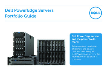
PERC H200.book Page 14 Tuesday, July 13, 2010 4:15 PMFigure 2-1.6Gbps SAS HBA Hardware Architecture1212 x4 external SAS connectors2PCI-E connectorOperating System SupportThe PERC H200 and 6Gbps SAS HBA cards support the followingoperating systems: Microsoft Windows Server 2003 family Microsoft Windows Server 2008 family, including Hyper-V Virtualization Microsoft Windows Server 2008 R2 Red Hat Enterprise Linux version 4.7, version 4.8, and version 5.3 SUSE Linux Enterprise Server version 10 Service Pack 2 (64-bit only),version 10 Service Pack 3 (64-bit only), and version 11 (64-bit only) Sun Solaris 10 (64-bit) VMware ESX 4.0 Update 1NOTE: For the latest list of supported operating systems and driver installationinstructions, see the system documentation on the Dell Support website atsupport.dell.com/manuals. For specific operating system service packrequirements, see the Drivers and Downloads section on the Dell Support websiteat support.dell.com.14Overview
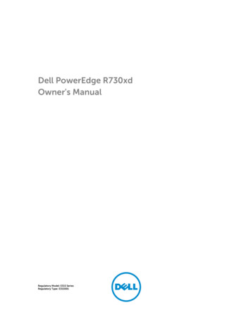
PERC H200.book Page 15 Tuesday, July 13, 2010 4:15 PMAbout RAIDRAID is a group of multiple independent physical disks that provide highperformance or better data availability by increasing the number of drivesused for saving and accessing data. A RAID disk subsystem improvesI/O performance and data availability. The physical disk group appears to thehost system as a single storage unit. Data throughput improves becausemultiple disks can be accessed simultaneously. RAID systems also improvedata storage availability and fault tolerance.RAID Levels RAID 0 uses disk striping to provide high data throughput, especially forlarge files in an environment that requires no data redundancy. RAID 1 uses disk mirroring so that data written to one physical disk issimultaneously written to another physical disk. This is good for smalldatabases or other applications that require small capacity, but completedata redundancy. RAID 10, a combination of RAID 0 and RAID 1, uses disk stripingacross mirrored disks. It provides high data throughput and completedata redundancy.CAUTION: Lost data on a RAID 0 disk cannot be recovered in the event ofa physical disk failure.RAID TerminologyRAID 0RAID 0 allows you to write data across multiple physical disks instead of justone physical disk. RAID 0 involves partitioning each physical disk storage spaceinto 64 KB stripes. These stripes are interleaved in a repeated sequentialmanner. The part of the stripe on a single physical disk is called a stripeelement.For example, in a four-disk system using only RAID 0, segment 1 is written todisk 1, segment 2 is written to disk 2, and so on. RAID 0 enhancesperformance because multiple physical disks are accessed simultaneously, butit does not provide data redundancy. Figure 2-2 shows an example of RAID 0.Overview15
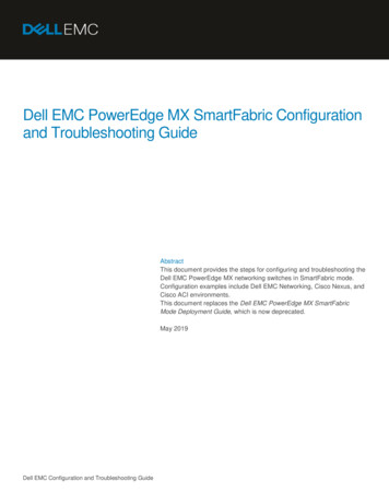
PERC H200.book Page 16 Tuesday, July 13, 2010 4:15 PMFigure 2-2.Example of RAID 0stripe element 1stripe element 5stripe element 9stripe element 2stripe element 6stripe element 10stripe element 3stripe element 7stripe element 11stripe element 4stripe element 8stripe element 12RAID 1With RAID 1, data written to one disk is simultaneously written to anotherdisk. If one disk fails, the contents of the other disk can be used to run thesystem and rebuild the failed physical disk. The primary advantage of RAID 1is that it provides 100 percent data redundancy. Because the contents of thedisk are completely written to a second disk, the system can sustain the failureof one disk. Both disks contain the same data at all times. Either physical diskcan act as the operational physical disk.NOTE: Mirrored physical disks improve read performance by read load balance.Figure 2-3.Example of RAID 1stripe element 1stripe element 2stripe element 3stripe element 416Overviewstripe element 1 duplicatedstripe element 2 duplicatedstripe element 3 duplicatedstripe element 4 duplicated
PERC H200.book Page 17 Tuesday, July 13, 2010 4:15 PMRAID 10RAID 10 requires two or more mirrored sets working together. MultipleRAID 1 sets are combined to form a single array. Data is striped across allmirrored drives. Since each drive is mirrored in RAID 10, no delay isencountered because no parity calculation is done. This RAID strategy cantolerate the loss of multiple drives as long as two drives of the same mirroredpair do not fail. RAID 10 volumes provide high data throughput andcomplete data redundancy.Figure 2-4.Example of RAID 10stripe element 1stripe element 3stripe element 5stripe element 7stripe element 1 duplicatedstripe element 3 duplicatedstripe element 5 duplicatedstripe element 7 duplicatedstripe element 2stripe element 4stripe element 6stripe element 8stripe element 2 duplicatedstripe element 4 duplicatedstripe element 6 duplicatedstripe element 8 duplicatedOverview17
PERC H200.book Page 18 Tuesday, July 13, 2010 4:15 PM18Overview
PERC H200.book Page 19 Tuesday, July 13, 2010 4:15 PMPERC H200 and 6Gbps SAS HBAFeaturesThis section provides the specifications of the Dell PowerEdge RAID Controller (PERC) H200 and 6Gbps SAS HBA cards.Table 3-1 compares the specifications of the PERC H200 Adapter andPERC H200 Integrated and PERC H200 Modular cards.Table 3-1.Specifications of PERC H200SpecificationPERC H200 AdapterPERC H200 IntegratedPERC H200 ModularSAS technologyYesYesYesSupport for x4or x8 PCI-EHost InterfaceYesYesYesHalf-Height,Half-LengthPCI AdapterHalf-Height,Half-LengthPCI AdapterCustomLSI SAS 2008LSI SAS 2008LSI SAS 2008Core Speed:533 MHzCore Speed:533 MHzCore Speed:533 MHzOperating voltage 12V, 3.3V,requirements 3.3Vaux 12V, 3.3V, 3.3Vaux 12V, 3.3V, 3.3VauxCommunication PCI-E lanesto the systemPCI-E lanesSystem dependentCommunication SAS Linksto end devicesSAS LinksSAS LinksSAS Connectors2x4 internal2x4 internalSAS connectivityrouted throughPCI-E connectorLead FreeYesYesYesForm FactorI/O Controller(IOC)PERC H200 and 6Gbps SAS HBA Features19
PERC H200.book Page 20 Tuesday, July 13, 2010 4:15 PMTable 3-1.Specifications of PERC H200 (continued)SpecificationPERC H200 AdapterPERC H200 Integrated PERC H200 Modular SupportedMicrosoft Windows Server 2003 family, Microsoftoperating systems Windows Server 2008 family, Windows Server 2008 R2, Red Hat Enterprise Linux version 4 Update 7 and later, version 5 Update 3and later, SUSE Linux Enterprise Server version 10 Service Pack 2and later (64-bit only), and version 11 Gold and later (64-bit only).Dell-compliantSAS and SATAcompatibilityYesDell supportedDell-compliantdirect connected physical disksend devicesYesYesDell-compliantphysical disksDell-compliantphysical disksSMART errorsupport portedsystemsYesYesYesHardware-basedRAIDRAID 0, RAID 1,RAID 10RAID 0, RAID 1,RAID 10RAID 0, RAID 1,RAID 10Maximumnumber ofvirtual disks222StoragemanagementsoftwareDellOpenManage Storage ServicesOpenManage Storage OpenManageServicesStorage ServicesNOTE: The management software that is supported depends on the specific platform.Support forinternal tapedriveYesNoNoSupport forGlobal HotspareYesYesYesMaximumnumber ofphysical disks1616420PERC H200 and 6Gbps SAS HBA Features
PERC H200.book Page 21 Tuesday, July 13, 2010 4:15 PMTable 3-1.Specifications of PERC H200 (continued)SpecificationPERC H200 AdapterPERC H200 IntegratedPERC H200 ModularMaximum10number ofphysical disksconfigured in asingle RAID disk104Maximumnumber ofconfigured disks(including hotspares)14414NOTE: The actual number of drives that is supported depends on the specific platformand expander support.6Gbps Expander YesSupportYesNoMaximumnumber ofHotspares222Table 3-2 lists the specifications of the 6Gbps SAS HBA.Table 3-2.Specifications of 6Gbps SAS HBASpecification6Gbps SAS HBASAS technologyYesSupport for x8, or x8 Full-SizePCI Express Host InterfaceYesForm FactorHalf-Size, Half-Length PCI AdapterI/O controller (IOC)LSI SAS 2008Core Speed533 MHzOperating voltage requirements 12V, 3.3V, 3.3VauxCommunication to the system PCI-E lanesCommunication to end devices SAS LinksConnectors2x4 Mini-SASPERC H200 and 6Gbps SAS HBA Features21
PERC H200.book Page 22 Tuesday, July 13, 2010 4:15 PMTable 3-2. Specifications of 6Gbps SAS HBASpecification6Gbps SAS HBALead FreeYesSupported operating systemsMicrosoft Windows Server 2003 family,Microsoft Windows Server 2008 family,Windows Server 2008 R2, Red Hat Enterprise Linuxversion 4 Update 7 and later, version 5 Update 3 andlater, SUSE Linux Enterprise Server version 10 ServicePack 2 and later (64-bit only), and version 11 Gold andlater (64-bit only).Dell-compliant SAS and SATA YescompatibilityDell-supported directconnected end devicesDell-supported external tape devices.Hot add or Hot remove of enddevicesYesSupport for external tape drive YesPort activity or status LEDsYesHardware-based RAIDNo22PERC H200 and 6Gbps SAS HBA Features
PERC H200.book Page 23 Tuesday, July 13, 2010 4:15 PMLED Port Activity Feature for 6Gbps SAS HBA OnlyThe 6Gbps SAS HBA controllers are equipped with port activity orstatus LEDs. The LEDs enable you to quickly determine the status ofan external SAS port. Each x4 connector has its own set of LEDs.Table 3-3 describes the color of the LEDs and corresponding SAS port state.Table 3-3.x4 Connector LEDs DescriptionLED ColorSAS Port StateOffIt means any one of the following: Power is off. Port has been reset. All links in the port are eitherdisconnected or the cable isdisconnected.GreenAll links in the port are connected andfunctional.AmberOne or more links in the port is notconnected. This is only applicablein a wide port configuration.PERC H200 and 6Gbps SAS HBA Features23
PERC H200.book Page 24 Tuesday, July 13, 2010 4:15 PMPhysical Disk Cache PolicyThe default cache policy on a physical disk is Enabled in SATA drives andDisabled on SAS drives. When physical disk caching is Enabled, disk I/Operformance is improved, but a power outage or equipment failure mightresult in data loss or corruption.NOTE: It is recommended that you use a backup power source for all Dellproduction systems.On a PERC H200 card, caching is forced to be disabled for all physical disksconfigured into a virtual disk, regardless of the drive type and default drivesettings.Unsupported DrivesDrives that are not certified by Dell are reported in the BIOS ConfigurationUtility, also known as Ctrl C .To view unsupported drives:1 In the BIOS Configuration Utility, navigate to the SAS Topology screen.2 Select the unsupported drive and press Alt D to view the DeviceProperties screen.The drive is marked as Uncertified in the Device Properties screen.Drives that are not certified by Dell are not blocked and you can use themat your own risk.24PERC H200 and 6Gbps SAS HBA Features
PERC H200.book Page 25 Tuesday, July 13, 2010 4:15 PMHardware InstallationThis chapter describes how to install the Dell PowerEdge RAID Controller (PERC) H200 and 6Gbps SAS HBA cards.Installing the PERC H200 and 6Gbps SAS HBACardsCAUTION: Many repairs may only be done by a certified service technician.You should only perform troubleshooting and simple repairs as authorized inyour product documentation, or as directed by the online or telephone service andsupport team. Damage due to servicing that is not authorized by Dell is notcovered by your warranty. Read and follow the safety instructions that camewith the product.1 Unpack the PERC H200 card or 6Gbps SAS HBA and check for damage.NOTE: Contact Dell if the controller is damaged.2 Turn off the system and attached peripherals, and disconnect the systemfrom the electrical outlet. See your system’s Hardware Owner’s Manualor the User’s Guide for more information on power supplies.3 Disconnect the system from the network and remove the cover of thesystem. See your system’s Hardware Owner’s Manual or the User’s Guidefor more information on opening the system.4 Select an appropriate PCI-E slot. If replacing a PERC H200 Adapter or6Gbps SAS HBA, remove the blank filler bracket on the back of thesystem aligned with the PCI-E slot you have selected.NOTE: For more information about your system’s PCI-E slots, see yoursystem’s Hardware Owner’s Manual.5 Align the controller to the PCI-E slot you have selected.Hardware Installation25
PERC H200.book Page 26 Tuesday, July 13, 2010 4:15 PM6 Insert the controller gently, but firmly, until the controller is firmly seatedin the PCI-E slot. See Figure 4-1.NOTE: Figure 4-1 displays the 6Gbps SAS HBA, but the installation instructionsin this section are common for the H200 Integrated, H200 Adapter and 6GbpsSAS HBA.NOTE: The H200 Integrated card may have a dedicated PCI slot. For additionaldetails, see the system’s Hardware Owner's Manual on the Dell Support website atsupport.dell.com.Figure 4-1. Installing a 6Gbps SAS HBA123261bracket screw3PCI-E slotHardware Installation26Gbps SAS HBA
PERC H200.book Page 27 Tuesday, July 13, 2010 4:15 PM7 Tighten the bracket screw, if any, or use the system’s retention clips tosecure the controller to the system’s chassis.8 For a PERC H200 card, connect the cables from the end devices or thebackplane of the system to the controller. See Figure 4-2.Figure 4-2. Connecting the Cable for PERC H2001321SAS x4 internal connector3PERC H200 Card2cable9 For the 6Gbps SAS HBA controller, connect the cable from the externalenclosure to the adapter. See Figure 4-3.NOTE: The external cable can be connected to either of the twoexternal connectors.Hardware Installation27
PERC H200.book Page 28 Tuesday, July 13, 2010 4:15 PMFigure 4-3.Connecting the Cable for 6Gbps SAS HBA1216Gbps SAS HBA2Cable from the external enclosure10 Replace the cover of the system. See your system’s Hardware Owner’sManual or the User’s Guide for more information on closing the system.11 Reconnect the power cable(s) and network cables, and then turnon the system.NOTE: Ensure that you do not connect a hard disk and tape drive to thesame PERC H200 card.NOTE: For information on connecting your PERC H200 card to a tape drive,see your system’s Hardware Owner’s Manual on the Dell Support websiteat support.dell.com/manuals.NOTE: Installing an operating system on a disk attached to the 6Gbps SAS HBAor a tape drive is not supported.28Hardware Installation
PERC H200.book Page 29 Tuesday, July 13, 2010 4:15 PMInstalling the PERC H200 Modular CardNOTE: For more information on removing and installing blade system parts,see your system’s Hardware Owner’s Manual or the User’s Guide from theDell Support website at support.dell.com.The storage controller card is located below the hard drive bays of theDell Blade system.To remove the storage controller card:1 Remove the Dell Blade system from the Blade system chassis.2 Remove the system cover of the Blade system.3 Remove the system board and place it on a stable and flat surface.4 Open the release lever to disconnect the storage controller card edgeconnector from the system board connector as illustrated in Figure 4-4.5 Lift the storage controller card straight up from the system board as illustratedin Figure 4-4.Figure 4-4. Removing and Installing the Storage Controller Card121storage controller card2release leverHardware Installation29
PERC H200.book Page 30 Tuesday, July 13, 2010 4:15 PMTo install your new storage controller card:1 Unpack
UCS-71, UCS-70, and UCSM-70 July 2010 Rev. A01 PERC H200.book Page 2 Tuesday, July 13, 2010 4:15 PM. Contents 3 Contents . and communicates with SAS devices using 2x4 mini-SAS external connectors. The PERC H200 Integrated Modular controller supports PCI-E