Transcription
AASHTO LRFD Bridge DesignSpecifications provisions forloss of prestressBrian D. Swartz, Andrew Scanlon, and Andrea J. SchokkerAnew method for estimating time-dependent lossof prestress was introduced in the 2005 interimrevisions of the American Association of StateHighway and Transportation Officials’ AASHTO LRFDBridge Design Specifications1 following the recommendations of the National Cooperative Highway ResearchProgram’s (NCHRP) report 496.2 The primary goal of theresearch documented in NCHRP report 496 was to updatethe methodology for estimating prestress loss, extendingits applicability to include high-strength concrete girders. The method that was developed (and has since beenadopted as AASHTO LRFD specifications article 5.9.5.4)is much more refined and rigorous than previous AASHTOmethods. The refinements, while in many ways making themethod more technically sound, introduce some nuancesthat can be confusing to practitioners more familiar withprevious approaches. The goal of this paper is to clarify theAASHTO LRFD specifications loss of prestress provisionsby demonstrating their foundation in basic mechanics. This paper details the time-dependent analysis method fordetermining loss of prestress in pretensioned bridge girders inthe American Association of State Highway and TransportationOfficials’ AASHTO LRFD Bridge Design Specifications. This paper aims to make the loss of prestress method morewidely understood and better applied in practice. This paper clarifies misconceptions related to transformed section properties and prestress gains.108Fall 2 0 1 2 PCI JournalThis paper follows the organization of the prestress lossprovisions currently in AASHTO. Each of the equationsappearing in article 5.9.5.4 will be described in detail,followed by a brief discussion of the shrinkage and creepmodels developed for high-strength concrete as recommended in NCHRP report 496 and currently shown in AASHTOLRFD specifications article 5.4.2. The time-dependentmaterial property models and the methods for estimatingprestress loss are independent of each other. In other words,any suitable shrinkage and creep models may be used in the
prestress loss method. Explanations of concepts that apply tomore than one equation are presented in detail following thecomprehensive description of the method. Finally, a discussion is offered to convey the authors’ perspective on thecurrent method and recommendations for improvement.four components: friction anchorage seatingMaterial property models prestressing steel relaxationUse of the AASHTO LRFD specifications prestress lossprovisions requires a method for calculating each of thefollowing material properties: elastic shortening concrete modulus of elasticity Ec concrete strain due to shrinkage εsh concrete creep strain εcr via a creep coefficient prestressing steel modulus of elasticity Ep prestressing steel relaxation fpRThe AASHTO LRFD specifications provide guidance oneach of these, with the most significant recent changesto the creep and shrinkage model. Those changes wereintroduced in the 2005 interim revisions following recommendations from NCHRP report 496. 2 The changes alsoincluded some slight modifications to the calculation ofconcrete elastic modulus and steel relaxation.Detailed information related to the AASHTO LRFD specifications material property model for high-strength concrete,along with a basic definition of the concrete creep coefficientused in the prestress loss provisions, is available in appendixA. Further documentation on the high-strength concretemodel is provided by Tadros et al.2 and Al-Omaishi et al.3Friction and anchorage seating are primarily of concern forposttensioned construction, although precasters must beaware of these two components as part of the pretensioningprocess. Precasters must also be aware of the relaxationlosses that occur between jacking and transfer. While someprecasters overjack to compensate for friction and seating losses, many do not overjack to counteract relaxationlosses before transfer. Designers should ensure that thesteel stress assumed just before transfer is realistic giventhe precasting environment and relaxation losses that occurduring fabrication. Guidelines for estimating relaxationlosses before transfer have historically been part of AASHTO LRFD specifications, but they are no longer providedas of the 2005 interim revisions. Relaxation before transferis not insignificant. In fact, approximately 1/4 of the totalrelaxation loss happens during the first day that the strandis held in tension as calculated by the intrinsic relaxationequation developed by Magura et al.4 Because the equation for relaxation before transfer is no longer included byAASHTO, Eq. (5.9.5.4.4b-2) is reproduced from the 20045AASHTO LRFD specifications here for convenience. Itapplies only to low-relaxation strands. f pR log(24t ) f pj 0.55 f pj 40 f py (AASHTO5.9.5.4.4b-2)Loss of prestresswhereIn the current AASHTO LRFD specifications methodology,loss of prestress is calculated in three stages:t time in days from stressing to transfer at transferfpj initial stress in the tendon after anchorage seating between transfer and the time of deck placementfpy specified yield strength of prestressing steel between the time of deck placement and final timeElastic shortening losses occur as the concrete respondselastically, and instantaneously, to the compressive loadtransferred from the bonded prestressing. The designer canconsider this effect in two different ways:The introduction of time of deck placement in the 2005interim revisions was a significant change from the previous method. The calculations required for each stage arediscussed in detail in the following paragraphs.Losses at transferLosses relative to the initial jacking stress immediatelyafter transfer of prestress to the concrete can be split into The elastic shortening loss of prestress—the difference in strand tension just after transfer and just before transfer—can be calculated explicitly. The loss ofprestress can be determined iteratively using AASHTO LRFD specifications Eq. (5.9.5.2.3a-1) or directlyusing Eq. (C5.9.5.2.3a-1). Stresses in the concrete arePCI Journal Fa l l 2012109
then determined by applying the effective prestressforce after transfer (the prestressing force before transfer minus the elastic shortening loss) to the net sectionconcrete properties. The use of gross section propertiesis typically an acceptable simplification. Superposition is applied for creep strains resultingfrom different stress increments Relationships between stress and strain in concreteand steel are prescribed.If only the concrete stresses need to be known and acalculation of effective prestressing force immediately aftertransfer is not needed, the use of transformed section properties may provide a more direct solution. In this case, theconcrete stresses can be found by applying the prestressingforce before transfer (not calculating any elastic shorteninglosses explicitly) to the transformed section properties. Theelastic shortening losses are accounted for implicitly by useof transformed section properties.The prestress loss method in the AASHTO LRFD specifications is split into two different periods: before andafter deck placement. In both periods, concrete shrinkage,concrete creep, and prestressing relaxation are considered.In this paper, the effects of differential deck shrinkage willbe treated separately to avoid the confusion that may follow if prestress gains due to deck shrinkage are combinedand superimposed incorrectly with prestress losses due tocreep, shrinkage, and relaxation.To calculate effective prestress and concrete stresses aftertransfer, a time-dependent analysis that considers shrinkageand creep of concrete and relaxation of prestressing steel isrequired.For both shrinkage and creep of concrete, the equations forchange in prestress are founded on Hooke’s law appliedto the prestressing steel, which is assumed linear elasticat all times. All equations are the product of the change inconcrete strain at the centroid of the prestressing strandsand the elastic modulus of prestressing steel. An effort wasmade to make the fundamental Hooke’s law relationshipreadily apparent in this paper by reformatting equations. Time-dependent loss of prestressThe time-dependent analysis method for estimating lossof prestress is independent of the material property modelused. No assumptions inherent in the time-dependentanalysis method impose concrete material characteristics.Therefore, the prestress loss method in the AASHTOLRFD specifications is not specific to high-strength concrete. Rather, it is a time-dependent analysis approach for aconcrete girder with bonded prestressing steel that references the concrete material property models in the AASHTO LRFD specifications developed for high-strengthconcrete. Any other suitable material property model couldbe used with the time-dependent analysis approach.Loss of prestress is calculated by tracing the change instrain in the prestressing steel that occurs with time dueto concrete strains caused by elastic, creep, and shrinkage deformations, along with losses due to relaxation. Theanalysis is based on strain compatibility and equilibrium inthe cross section at any time along with prescribed stressstrain relationships for steel and concrete. The time-dependent analysis approach is more straightforward than thecomplex equations in the AASHTO LRFD specificationssuggest. The basic assumptions inherent in the time-dependent analysis method are as follows:110 Pure beam behavior; that is, plane sections remain plane. Strain compatibility; that is, perfect bond between theconcrete and prestressing steel. Therefore the changein strain in the prestressing steel is equal to the changein strain in the surrounding concrete. As required for equilibrium, internal forces equalexternal forces.Fall 2 0 1 2 PCI JournalConcrete shrinkage before deck placementThe prestress loss due to shrinkage fpSR is given byAASHTO LRFD specifications Eq. (5.9.5.4.2a-1). f pSR ε bid E p K id(AASHTO 5.9.5.4.2a-1)whereεbid shrinkage strain of girder concrete between time oftransfer or end of curing and time of deck placementKid transformed section coefficient that accounts fortime-dependent interaction between concrete and bondedsteel in section being considered for period between transfer and deck placementThe terms in Eq. (5.9.5.4.2a-1) can be regrouped as shownin Eq. (1). f pSR E p ( ε bid K id )(1)Hooke’s law is clearly evident in Eq. (1). The concrete strainat the centroid of the prestressing steel is the product εbidKid.The Kid term is an adjustment to the free shrinkage strain ofconcrete εbid during this time to account for the time-dependent interaction between concrete and bonded steel, whichprovides some internal restraint against shrinkage. It arisesfrom considerations of strain compatibility and equilibriumon the cross section. Kid is discussed in detail later in thispaper. In addition, a derivation of the equation is provided inappendix B. The subscripts b, i, and d in the shrinkage strain
term represent beam (girder), initial time (transfer or start ofcuring), and deck placement time td.Concrete creep before deck placement The prestress loss due to creep fpCR is given by AASHTO LRFDspecifications Eq. (5.9.5.4.2b-1). f pCR EpEcif cgpψ b ( td , ti ) K id(AASHTO5.9.5.4.2b-1)loss of prestress due to relaxation is small and varies overa small range. Therefore, the specifications recommendassuming a total relaxation from transfer to final time of2.4 ksi (16.5 MPa), with half of that assumed to occurbefore deck placement fpR1.Girder concrete shrinkage after deck placement The equation for shrinkage losses after deckplacement fpSD mirrors that for losses before deck placement and is given by AASHTO LRFD specificationsEq. (5.9.5.4.3a-1). f pSD ε bdf E p K df (AASHTO 5.9.5.4.3a-1)whereEci modulus of elasticity of concrete at transferwherefcgp concrete stress at centroid of prestressing tendonsdue to the prestressing force immediately aftertransfer and self-weight of the member at sectionof maximum momentεbdf shrinkage strain of girder concrete after deck placementψb(td,ti) creep coefficient for girder concrete at the time tdof deck placement due to loading applied at thetime at transfer tiThe terms in Eq. (5.9.5.4.2b-1) can be regrouped as shownin Eq. (2). f pCR f cgp E p ψ b ( td , ti ) K id Eci (2)Hooke’s law is again seen in Eq. (2) with the term f cgp ψ b ( td , ti ) K id Eci as the concrete strain due to creep at the centroid of theprestressing steel. The termf cgpEciis the elastic strain in the concrete at the prestressing centroid due to stresses applied at transfer. The product of thiselastic strain and the girder creep coefficient at the time ofdeck placement td due to stresses applied at time ti results inthe creep strain in the concrete at the centroid of prestressing. As with the shrinkage strain, the transformed section coefficient Kid is used to represent the internal restraint offeredby the bonded prestressing steel against concrete creep.Kdf transformed section coefficient that accounts fortime-dependent interaction between concrete andbonded steel in section being considered after deckplacementThe terms in Eq. (5.9.5.4.3a-1) can be regrouped as shownin Eq. (3). f pSD E p ( ε bdf K df(3)The concrete strain at the centroid of the prestressing steelover this period is the product εbdfKdf. Kdf is a transformedsection coefficient analogous to Kid, except that it is developed for use with the properties of the full composite(girder plus deck) cross section. The shrinkage strain fromafter deck placement εbdf is calculated most readily whenrecognizing that it is the difference between final shrinkagestrain and that at the time of deck placement (Eq. [4]).ε bdf ε bif ε bid(4)whereεbif shrinkage strain of girder concrete between time oftransfer or end of curing and final timeConcrete creep after deck placement Theequation for creep losses after deck placement fpCD isthe sum of creep effects due to stresses applied at transferand stresses applied after transfer. It is given by AASHTOLRFD specifications Eq. (5.9.5.4.3b-1). f pCD Prestressing steel relaxation before deckplacement The AASHTO LRFD specifications provideguidance for a detailed calculation of prestressing steelrelaxation, but when low-relaxation strands are used the)EpEcif cgp ψ b ( t f , ti ) ψ b ( td , ti ) K dfEp f cd ψ b ( t f , td ) K df(AASHTO 5.9.5.4.3b-1)Ec PCI Journal Fa l l 2012111
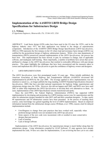
Figure 1. Schematic summary of the components affecting prestress losses due to creep. Note: Ec modulus of elasticity of concrete at 28 days; Eci modulus ofelasticity of concrete at transfer; fcgp concrete stress at centroid of prestressing tendons due to prestressing force immediately after transfer and self-weight ofmember at section of maximum moment; td age of girder concrete at time of deck placement; tf age of girder concrete at end of time-dependent analysis; ti ageof girder concrete at time of prestress transfer; fcd change in concrete stress at centroid of prestressing strands due to time-dependent loss of prestress betweentransfer and deck placement, combined with deck weight and superimposed loads; ψb(td,ti) creep coefficient for girder concrete at time td of deck placement due toloading applied at time ti of transfer; ψb(tf,td) creep coefficient for girder concrete at final time tf due to loading applied at time td of deck placement; ψb(tf,ti) creepcoefficient for girder concrete at final time tf due to loading applied at time of transfer.whereψb(tf,ti) creep coefficient for girder concrete at final timetf due to loading applied at the time ti of transfer fcd change in concrete stress at centroid of prestressing strands due to time-dependent loss ofprestress between transfer and deck placementcombined with deck weight and superimposedloadsψb(tf,td) creep coefficient for girder concrete at final timetf due to loading applied at time td of deck placementThe terms in Eq. (5.9.5.4.3b-1) can be regrouped as shownin Eq. (5).112Fall 2 0 1 2 PCI Journal f cgp f pCD E p ψ b ( t f , ti ) ψ b ( td , ti ) K df Eci f E p cd ψ b ( t f , td ) K df Ec (5)The first term accounts for the creep effects, due to theinitial prestressing, that continue after deck placement.This is calculated as the difference between the finalcreep effects and those already considered at the time ofdeck placement in Eq. (2). The term [ψb(tf,ti) – ψb(td,ti)] isnot equal to ψb(tf,td) because the creep function is drivenlargely by the time when the stress changed. The secondterm in Eq. (5) will generally be opposite in sign relativeto the first. The initial stress at transfer fcgp will typicallybe compression, while the changes in stress due to deckweight, superimposed dead load, and loss of prestress willtypically be tensile stress increments. Figure 1 clarifies the
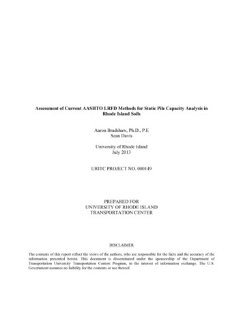
PdeckDeckPdeckGirderElevationSectionFigure 2. Conceptual model of the effect that deck-girder differential shrinkage has on the composite cross section. Note: Pdeck effective force due to deck shrinkage applied to composite section at centroid of deck.superposition of the effects. Again, the transformed sectioncoefficient Kdf is used to model the restraint of creep bythe bonded prestressing steel. The time-dependent loss ofprestress is shown to occur instantaneously for clarity ofthe graphic. In reality, it would occur gradually.Prestressing steel relaxation after deck placement If a total loss of prestress due to relaxation of 2.4 ksi(16.5 MPa) is assumed, as recommended by the AASHTOLRFD specifications, half of that value should be takenbetween deck placement and final time fpR2.tensile stress increment, too. A further discussion of elasticgains is provided later in this paper.An explanation of the article 5.9.5.4.3d equations relatedto shrinkage of deck concrete is warranted. First, theprestress gain due to deck shrinkage fpSS is calculated byAASHTO LRFD specifications Eq. (5.9.5.4.3d-1). f pSS EpEc f cdf K df 1 0.7ψ b ( t f , td ) (AASHTO5.9.5.4.3d-1)Shrinkage of the deck concretewhereStarting with the 2005 interim revisions, the AASHTOLRFD specifications method for estimating loss of prestress recognized the interaction between a cast-in-placedeck and a precast concrete girder when they are compositely connected. The shrinkage differential exists primarilybecause much of the total girder concrete shrinkage occursbefore the system is made composite. Therefore, while thegirder and deck behave compositely, the deck has greaterpotential shrinkage. Strain compatibility at the deck-girderinterface, however, requires that the two elements behaveas one unit; therefore, an internal redistribution of stressesis necessary.The effect of differential shrinkage can be modeled as aneffective force at the centroid of the deck (Fig. 2).In typical construction, the deck is above the neutral axisof the composite section and the centroid of the prestressing steel is below the neutral axis at the critical section.The effective compressive force due to differential shrinkage causes a tensile strain on the opposite face (bottom)of the girder. Assuming strain compatibility between theprestressing steel and the surrounding concrete, the tensilestrain leads to an increase in the effective force in the prestressing steel. The AASHTO LRFD specifications methodcalls this a prestressing gain. This prestressing gain,however, does not increase the compressive stress in thesurrounding concrete. Rather, the concrete experiences a fcdf change in concrete stress at centroid of prestressingstrands due to shrinkage of deck concreteThe terms in AASHTO Eq. (5.9.5.4.3d-1) can be regrouped as shown in Eq. (6). f pSS f cdf K Ep df Ec 1 0.7ψ ( t , t ) bfd (6)The term in the outer parentheses in Eq. (6) is the strain atthe prestressing steel centroid due to deck shrinkage. Thestrain is found through division of the stress change bythe age-adjusted effective modulus (rather than the elasticmodulus of concrete) because the effective force due todeck shrinkage builds up over time and is partially relievedby creep. A detailed description of age-adjusted effectivemodulus is provided later in this paper.The AASHTO LRFD specifications recommend calculating the stress change caused by the effective deck shrinkage force at the centroid of the prestressing steel usingPCI Journal Fa l l 2012113
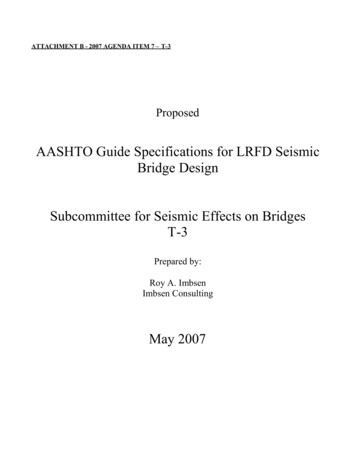
Eq. (5.9.5.4.3d-2), which is split into its components inEq. (7) and (8) for clarity. 1 e pc ed f cdf Pdeck Ic AcAl-Omaishi et al.,6 calculates extreme bottom fiber concretestress fcbSS using the effective force defined in Eq. (8). K df (9)wherewherePdeck effective force due to deck shrinkage applied tocomposite section at centroid of deck; Pdeck is defined for the purposes of this paper only and is not avariable used in AASHTO LRFD specificationsybc eccentricity of concrete extreme bottom fiber withrespect to centroid of composite cross sectionAc area of composite cross sectionepc e ccentricity of prestressing force with respectto centroid of composite section, positive wherecentroid of prestressing steel is below centroid ofcomposite sectioned eccentricity of deck with respect to gross compositesection, positive where deck is above girderIc moment of inertia of composite cross sectionThe effective force due to deck shrinkage can be calculatedas the product of shrinkage strain, elastic modulus, andeffective deck area (Eq. [8]). Because the gradual buildupof stress will be partially relieved by simultaneous creepof the deck concrete, an age-adjusted effective modulus isused in place of the concrete elastic modulus. Ecd Pdeck ε ddf Ad 1 0.7ψ d ( t f , td ) (8)whereεddf shrinkage strain of deck concrete between timeof deck placement or end of deck curing andfinal timeEcd modulus of elasticity of deck concreteψd(tf,td) creep coefficient for deck concrete at final time tfdue to loading applied at time td of deck placementAd effective cross-sectional area of composite deckconcreteThe AASHTO LRFD specifications guide the user tocalculate a stress change at the centroid of the prestressingsteel and the prestressing gain due to deck shrinkage but stopshort of providing a prescriptive equation to calculate concrete stress at the extreme fiber. Equation (9), published by114 1 y e f cbSS Pdeck bc dIc Ac(7)Fall 2 0 1 2 PCI JournalMaintaining a consistent sign convention for Eq. (7) and(9) is a challenge. In typical construction, Pdeck will be aneffective compression force and fcbSS will be a tensilestress increment in the extreme bottom concrete fiber.The effective force Pdeck, will be present on the compositecross section even if the deck concrete is cracked becausethe force will be transferred by reinforcement across thecracks and will eventually be carried into the girder via thecomposite connection.Transformed sectioncoefficients Kid and KdfThe transformed section coefficients represent the factthat steel restrains the creep and shrinkage of concrete.Because the two materials are bonded, the differences intime-dependent behavior lead to an internal redistributionof stress. In addition, the difference in elastic responsebetween steel and concrete must be considered in the stressredistribution.Consider shrinkage as an example. Figure 3 shows εsh asthe shrinkage expected of a concrete specimen that has norestraint against shortening (that is, no reinforcement). Suchan idealized type of specimen was used in developing themodel used to predict shrinkage strains. In a prestressedconcrete girder, however, there is restraint against shrinkage because the prestressing steel bonded to the concretedoes not shrink. Because strain compatibility must besatisfied, equilibrium requires a redistribution of stresses toaccommodate the differences in time-dependent and elasticbehavior of the two materials. In Fig. 3, εres is used to denotethe amount by which the free shrinkage is reduced at thelevel of the prestressing centroid by bonded steel. The netshortening at the centroid of prestressing is εnet. The transformed section coefficient is derived to quantify the effect ofthe prestressing steel’s restraint. It can be thought of as thesimple ratio given in Eq. (10).K id ε netε sh(10)Kid and Kdf represent the same phenomenon. Kid is derived
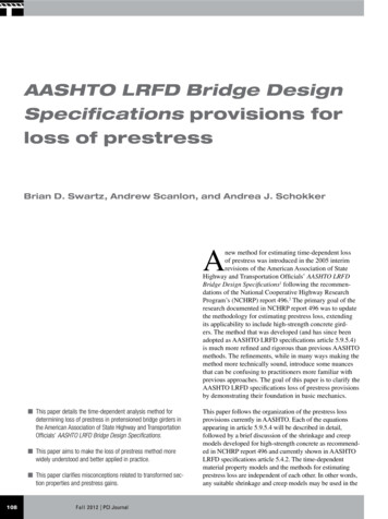
AneApStrain datumFree (unrestrained) shrinkageShortening strainResultant strain distribution,considering restraint frombonded prestressing steelεnetεresεshGirder sectionGirder elevationStrain distributionFigure 3. Bonded prestressing steel partially restrains the free shrinkage strain inherent to the concrete. The effect is represented mathematically by the transformedsection coefficient. Note: An area of net cross section; Ap area of prestressing steel; e eccentricity between the centroid of the girder concrete and the centroidof the prestressing steel; εnet net shrinkage strain of section at centroid of prestressing steel considering shrinkage of concrete and restraint against shrinkage frombonded prestressing steel; εres portion of free shrinkage of concrete effectively restrained by bonded prestressing steel at centroid of prestressing steel;εsh concrete strain due to shrinkage.with respect to the girder only and is used for calculationsbefore deck placement, while Kdf is derived for the girder-deckcomposite system. A detailed derivation is in appendix B.whereEc,effAge-adjusted effective modulusThe AASHTO LRFD specifications account for the creepof concrete by using an age-adjusted effective modulus insome instances. The method approximates the principleof creep superposition attributed to McHenry7 for a timevarying stress history. Figure 4 shows the general relationship between elastic modulus, effective modulus, andage-adjusted effective modulus. When a change in stressin concrete fc is applied instantaneously, the short-termstrain can be calculated according to the elastic modulus Ecfor the concrete. If the stress is maintained, the strain willincrease gradually as concrete creeps (from point A to Bin Fig. 4). The net behavior of the concrete can be approximated by defining an effective elastic modulus (Eq. [11])to describe the cumulative stress-strain behavior from theorigin to point B.Ec , effEc 1 ψ ( t , ti ) effective modulus of elasticity of concrete usedto describe the response of concrete to an instantaneous stress increment considering both elasticand creep effectsψ(t,ti) creep coefficient for concrete at time t due tostresses applied at time of a stress change tiIf the stress change is not instantaneous, the creep responseof concrete is slightly less. Figure 4 shows the differenceschematically, where the stress change has been splitinto three equal increments (rather than a truly gradualincrease) for the purpose of clarity in the graphic. If thestress builds over time, the total creep strain is less thanwhen the same stress change is instantaneous. Equation (11) is adjusted slightly to yield Eq. (12) to representan age-adjusted effective modulus of concrete Ec,AAEM.Ec , AAEM EcEc 1 χ ψ ( t , ti ) 1 0.7 ψ ( t , ti ) (12)(11)whereχ aging coefficientPCI Journal Fa l l 2012115
Figure 4. Schematic definition of an effective modulus and age-adjusted effective modulus as used to account for the creep response of concrete. Note: Ec modulusof elasticity of concrete; Ec,AAEM age-adjusted effective elastic modulus of concrete used to describe response of concrete to gradual stress increment considering both elastic and creep effects; Ec,eff effective modulus of elasticity of concrete used to describe the response of concrete to an instantaneous stress incrementconsidering both elastic and creep effects.The aging coefficient χ was first proposed by Trost8,9 in1967, then refined by Bazant10 and Dilger.11 The AASHTOLRFD specifications adopt a constant value of 0.7 for χ. Adescription of the method is also available in Collins andMitchell.12after jacking. Therefore, the tension is less than at the timeof jacking. This loss of stress in the prestressing steel dueto shortening of the concrete at transfer results in less precompression of the concrete. This point will be contrastedwith the idea of an elastic gain.Elastic losses and gainsAn analogy to reinforced (nonprestressed) concrete helpsto clarify the concept. When a reinforced concrete beamis loaded (Fig. 5), tension stresses and eventually cracking would be expected on the bottom face of a simplysupported beam. As load is applied to the beam, the steelundergoes an elongation and therefore takes on a tensileforce. As a result of the applied load, the steel experiencesa gain in tension. This force would not be considered tobe precompressing the concrete in this region or acting toresist the formation of cracks. The tension gain in the steelfollows an elongation that is also experienced by the surrounding concrete, rendering a tensile stress increment inthe concrete as well as the steel.Prestress loss occurs when the strain in the steel decreasesto match the shortening of concrete at the same level as thesteel. The application of load, however, such as the deckweight at time of deck placement, causes an elongation inthe prestressing steel and a corresponding increase in steelstress. The application of load also causes an increment oftensile stress in the concrete at the level of the steel. Use ofthe term prestress gain to describe this elastic response toload causes confusion. The following discussion attemptsto clarify the matter.The elastic shortening loss at transfer is well understood,and th
Highway and Transportation Officials' AASHTO LRFD Bridge Design Specifications1 following the recommen-dations of the National Cooperative Highway Research Program's (NCHRP) report 496.2 The primary goal of the . LRFD specifications is not specific to high-strength con-crete. Rather, it is a time-dependent analysis approach for a .