Transcription
ATTACHMENT B - 2007 AGENDA ITEM 7 – T-3ProposedAASHTO Guide Specifications for LRFD SeismicBridge DesignSubcommittee for Seismic Effects on BridgesT-3Prepared by:Roy A. ImbsenImbsen ConsultingMay 2007
SECTION 1: INTRODUCTIONTABLE OF CONTENTSTO BE UPDATED BY AASHTO PUBLICATIONS1.1 BACKGROUND . 1-11.2 PROJECT ORGANIZATION . 1-31.2.1 Technical Review Team. 1-31.2.2 Project Direction from AASHTO T-3 . 1-41.2.3 Technical Assistance Agreement Between AASHTO and USGS. 1-51.3 FLOW Charts. 1-61-i
SECTION 1INTRODUCTION1.1 BACKGROUNDC1.1The AASHTO Guide Specifications for LRFD SeismicBridge Design is established in accordance with theNCHRP 20-07/Task 193 Task 6 Report. Task 6 containsfive (5) Sections corresponding to Tasks 1 to 5 as follows:SECTION 1 includes a review of the pertinentdocuments and information that were available.SECTION 2 presents the justification for the 1000year return period (which is approximately equivalent to a7% probability of exceedance in 75 years) asrecommended for the seismic design of highway bridges.SECTION 3 includes a description of how the “noanalysis” zone is expanded and how this expansion isincorporated into the displacement based approach.SECTION 4 describes the two alternative approachesavailable for the design of highway bridges with steelsuperstructures and concludes with a recommendation touse a force based approach for steel superstructures.SECTION 5 describes the recommended procedurefor liquefaction design to be used for highway bridges.This aspect of the design is influenced by therecommended design event and the no analysis zonecovered in Tasks 2 and 3, respectively. Therecommendations proposed are made taking into accountthe outcome of these two tasks for Seismic DesignCategory D.The following recommendations are documented:This commentary is included to provide additionalinformation to clarify and explain the technical basis forthe specifications provided in the Guide Specifications forLRFD Seismic Bridge Design. These specifications are forthe design of new bridgesThe term “shall” denotes a requirement forcompliance with these Specifications.The term “should” indicates a strong preference for agiven criterion.The term “may” indicates a criterion that is usable, butother local and suitably documented, verified, andapproved criterion may also be used in a manner consistentwith the LRFD approach to bridge design.The term “recommended” is used to give guidancebased on past experiences. Seismic design is a developingfield of engineering, which has not been uniformly appliedto all bridge types and thus the experiences gained to dateon only a particular type are included as recommendations.Task 2xAdopt the 7% in 75 years design event fordevelopment of a design spectrum.xEnsure sufficient conservatism (1.5 safety factor)for minimum support length requirement. Thisconservatism is needed to accommodate the fullcapacity of the plastic hinging mechanism of thebridge system. This conservatism shall beembedded in the specifications to addressunseating vulnerability. At a minimum it isrecommended to embed this safety factor for sitesoutside of California.xPartition Seismic Design Categories (SDC’s) intofour categories and proceed with the developmentof analytical bounds using the 7% in 75 yearsdesign event.1-1
1-2AASHTO GUIDE SPECIFICATIONS FOR LRFD SEISMIC BRIDGE DESIGNTask 3Establish four Seismic Design Categories with thefollowing requirements:xSDC Aa. No Displacement Capacity Check Neededb. No Capacity Design Requiredc. SDC A Minimum RequirementsxSDC Bd. Implicit Displacement Capacity CheckRequired (i.e., use a Closed Form SolutionFormula)e. No Capacity Design Requiredf. SDC B Level of DetailingxSDC Ca. Implicit Displacement Capacity CheckRequiredb. Capacity Design Requiredc. SDC C Level of DetailingxSDC Dd. Pushover Analysis Requirede. Capacity Design Requiredf. SDC D Level of DetailingTask 4Recommended the following for SDC C & D:xAdopt AISC LRFD Specifications for design ofsingle-angle members and members with stitchwelds.xAllow for three types of a bridge structuralsystem as adopted in SCDOT Specifications.Type 1 – Design a ductile substructure withan essentially elastic superstructure.Type 2 – Design an essentially elasticsubstructure with a ductile superstructure.Type 3 – Design an elastic superstructure andsubstructure with a fusing mechanism at theinterface between the superstructure and thesubstructure.xAdopt a force reduction factor of 3 for design ofnormal end cross-frame.xAdopt NCHRP 12-49 for design of “Ductile EndDiaphragm” where a force reduction factorgreater than 3 is desired.
SECTION 1: INTRODUCTIONTask 5The following list highlights the main proposedliquefaction design requirements:xLiquefaction design requirements are applicableto SDC D.xLiquefaction design requirements are dependenton the mean magnitude for the 7% Probability ofExceedance in 75-year event and the normalizedStandard Penetration Test (SPT) blow count[(N1)60 ].xIf liquefaction occurs, then the bridge shall bedesigned and analyzed for the Liquefied andNon-Liquefied configurations.Detailed design requirements and recommendationsfor lateral flow have not yet reached a level ofdevelopment suitable for inclusion in this document.However, limited information and guidance on lateral flowis provided.1.2 PROJECT ORGANIZATIONThe NCHRP Project was organized to assist theAASHTO T-3 Subcommittee for Seismic Design ofBridges to complete another step towards producingLRFD seismic design provisions for inclusion into theAASHTO LRFD Bridge Design Specifications. The T-3Subcommittee defined very specific tasks as described inArticle 1.1 above that it envisioned were needed tosupplement the existing completed efforts (i.e., AASHTODivision I-A, NCHRP 12-49 Guidelines, SCDOTSpecifications, Caltrans Seismic Design Criteria, NYDOTSeismic Intensity Maps and ATC-32) to yield aspecification for AASHTO which can be implemented.The tasks have now been completed by TRC/Imbsen &Associates, Inc. under the direction of the T-3Subcommittee and the assistance of their Board ofReviewers to yield a stand-alone Guide Specification thatcan be evaluated by AASHTO and considered for adoptingin 2007. This project was completed by Imbsen Consultingunder a subcontract with TRC/Imbsen & Associates, Inc.1.2.1 Technical Review TeamThe final stages for completing the GuideSpecifications contained herein encompassed two primarytasks. Several states across the U.S. performed trial bridgedesigns using preliminary drafts. The trial design bridgeconfigurations and soil types employed were typical foreach of the participating states. After completion of thesetrial designs, a technical team was formed whichcooperatively addressed questions, concerns and technicalissues in order to bring the Guide Specifications into their1-3
1-4AASHTO GUIDE SPECIFICATIONS FOR LRFD SEISMIC BRIDGE DESIGNfinal published form.The states who performed the trial designs n StateThe members of the technical review team were:xxxxxxxxxxxMark Mahan, CA DOT (Team Leader)Roy A. Imbsen, Imbsen ConsultingElmer Marx, AK DOT & PFJay Quiogue, CA DOTChris Unanwa, CA DOTFadel Alameddine, CA DOTChyuan-Shen Lee, WA State DOTStephanie Brandenberger, MT DOTDaniel Tobias, IL DOTDerrell Manceaux, FHWALee Marsh, Berger/Abam1.2.2 Project Direction from AASHTO T-3The T-3 Working Group that defined the projectobjectives and directed the project include:xxxxxxxxRick Land, CA (Past chair)Harry Capers, NJ (Past Co-chair)Richard Pratt, AK (Current chair)Kevin Thompson, CA (Current Co-chair)Ralph Anderson, ILJugesh Kapur, WAEd Wasserman, TNPaul Liles, GAThe project team members and reviewers thatparticipated in the NCHRP 20-07/193 include:xxxxxxxxRoger Borcherdt, USGSPo Lam, Earth Mechanics, Inc.Ed V. Leyendecker, USGSLee Marsh, Berger/AbamRandy Cannon, Site BlauveltGeorge Lee, MCEER, ChairGeoff Martin, MCEERJoe Penzien, HSRC, EQ V-team
SECTION 1: INTRODUCTIONxxxxxxxxxxxxxxxxxxxJohn Kulicki, HSRCLes Youd, BYUJoe Wang, Parsons, EQ V-teamLucero Mesa, SCDOT V-teamDerrell Manceaux, FHWAPeter W. Osborn, FHWAAlexander K. Bardow, Mass. HighwayStephanie Brandenberger, Montana DOTBruce Johnson, Oregon DOTMichael Keever, Calif. DOTJerry O’Connor, MCEERRoland Nimis, FHWAW. Phil Yen, FHWAFiras Ibrhim, FHWAShyam Gupta, MODOTElmer E. Marx, Alaska DOT & PFWilliam Crawford, Nevada DOTJugesh Kapur, Washington State DOTJohn Jordan, Indiana DOT1.2.3 Technical Assistance Agreement BetweenAASHTO and USGSUnder the agreement the USGS prepared two types ofproducts for use by AASHTO. The first product was a setof paper maps of selected seismic design parameters for a7% probability of exceedance in 75 years. The secondproduct was a ground motion software tool to simplifydetermination of the seismic design parameters.These guidelines use spectral response accelerationwith a 7% probability of exceedance in 75 years as thebasis of the seismic design requirements. As part of theNational Earthquake Hazards Reduction Program, the U.S.Geological Survey’s National Seismic Hazards MappingProject prepares seismic hazard maps of different groundmotion parameters with different probabilities ofexceedance. However maps were not prepared for theprobability level required for use by these guidelines.These maps were prepared by the U.S. Geological Surveyunder a separate Technical Assistance Agreement with theAmerican Association ofState Highway andTransportation Officials (AASHTO), Inc. for use byAASHTO and in particular the Highway Subcommittee onBridges and Structures.MapsThe set of paper maps covered the fifty states of theU.S. and Puerto Rico. Some regional maps were alsoincluded in order to improve resolution of contours. Mapsof the conterminous 48 states were based on USGS dataused to prepare maps for a 2002 update. Alaska was basedon USGS data used to prepare a map for a 2006 update.Hawaii was based on USGS data used to prepare 1998maps. Puerto Rico was based on USGS data used toprepare 2003 maps.1-5
1-6AASHTO GUIDE SPECIFICATIONS FOR LRFD SEISMIC BRIDGE DESIGNThe maps included in the map package were preparedin consultation with the Subcommittee on Bridges andStructures. The package included a series of maps thatprovide:xthe peak horizontalcoefficient, PGAxa short period (0.2 sec) value of spectralacceleration coefficient, Ssxa longer period (1.0 sec) value of spectralacceleration coefficient, S1groundaccelerationThe maps are for spectral accelerations for a referenceSite Class B.Ground Motion ToolThe ground motion software tool was packaged on aCD-ROM for installation on a PC using a Windows-basedoperating system. The software includes features allowingthe user to calculate the mapped spectral responseaccelerations as described below:xPGA, Ss , and S1: Determination of the parametersPGA, Ss, and S1 by latitude-longitude or zip codefrom the USGS data.xDesign values of PGA, Ss, and S1: Modificationof PGA, Ss , and S1 by the site factors to obtaindesign values. These are calculated using themapped parameters and the site coefficients for aspecified site class.In addition to calculation of the basic parameters, theCD allows the user to obtain the following additionalinformation for a specified site:xCalculation of a response spectrum: The user cancalculate response spectra for spectral responseaccelerations and spectral displacements usingdesign values of PGA, Ss , and S1. In addition tothe numerical data the tools include graphicdisplays of the data. Both graphics and data canbe saved to files.xMaps: The CD also include the 7% in 75 yearmaps in PDF format. A map viewer is includedthat allows the user to click on a map name froma list and display the map.1.3 FLOW CHARTSIt is envisioned that the flow charts herein will providethe engineer with a simple reference to direct the designprocess needed for each of the four Seismic Design
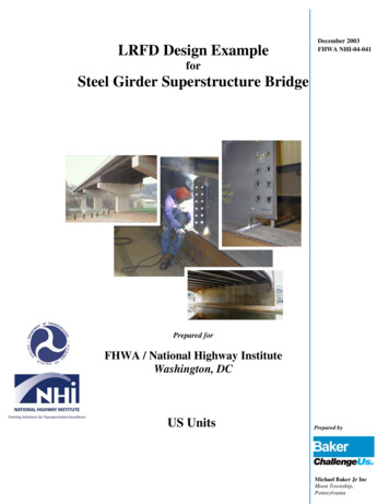
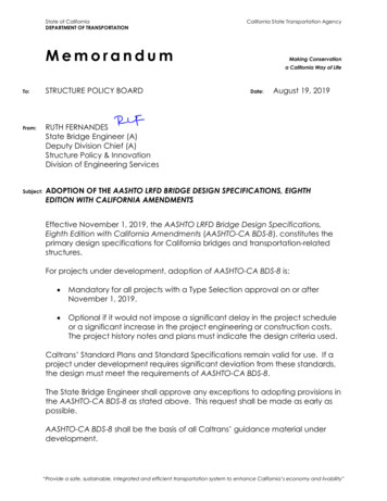
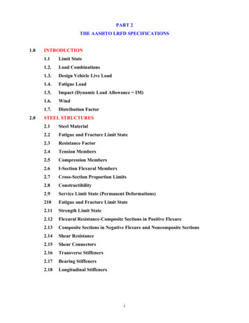
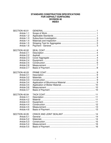
SECTION 1: INTRODUCTIONCategories (SDC).Flow charts outlining the steps in the seismic designprocedures implicit in these specifications are given inFigures 1a to 6.The Guide Specifications were developed to allowthree Global Seismic Design Strategies based on thecharacteristics of the bridge system, which include:Type 1 -Design a ductile substructure with anessentially elastic superstructure.Type 2 -Design an essentially elastic substructure with a ductile superstructure.Type 3 -Design an elastic superstructure andsubstructure with a fusing mechanism atthe interface between the superstructureand the substructure.The flow chart in Figure 1a guides the designer on theapplicability of the specifications and the breadth of thedesign procedure dealing with a single span bridge versusa multi-span bridge and a bridge in Seismic DesignCategory A versus a bridge in Seismic Design Category B,C, or D.Figure 1b shows the core flow chart of proceduresoutlined for bridges in SDC B, C, and D. Figure 2 outlinesthe demand analysis. Figure 3 directs the designer todetermine displacement capacity. Figure 4 shows themodeling procedure. Figures 5a & 5b establish memberdetailing requirements based on the type of the structurechosen for seismic resistance. Figure 6 shows thefoundation design.1-7
1-8AASHTO GUIDE SPECIFICATIONS FOR LRFD SEISMIC BRIDGE DESIGNPRELIMINARY DESIGN BRIDGETYPE SELECTION AND DESIGNFOR SERVICE LOADSAPPLICABILITY OFSPECIFICATIONSARTICLE 3.1YESTEMPORARYBRIDGEARTICLE 3.6NOPERFORMANCE CRITERIAARTICLE 3.2FOUNDATION INVESTIGATIONARTICLE 6.2EARTHQUAKE RESISTING SYSTEMS (ERS)REQUIREMENTS FOR SDC C & DARTICLE 3.3DETERMINE DESIGN RESPONSE SPECTRUMARTICLE 3.4DETERMINE SEISMIC DESIGN CATEGORY (SDC)ARTICLE 3.5YESSDC ADETERMINE DESIGN FORCESNOARTICLE 4.6YESSINGLE SPANBRIDGEDETERMINE MINIMUMSUPPORT LENGTHARTICLE 4.12DETERMINE DESIGN FORCESNOARTICLE 4.5SEISMIC DESIGN CATEGORY B, C, DFOUNDATION DESIGNSee Figure 1.3-1BFigure 1.3-6DESIGN COMPLETEFigure 1.3-1a Seismic Design Procedure Flow Chart.DETERMINE MINIMUMSUPPORT LENGTHARTICLE 4.12DESIGN COMPLETE
SECTION 1: INTRODUCTION1-9(Continued From Figure 1.3-1A)NoSDC CYesSDC DYesYesDISPLACEMENTDEMAND ANALYSISDISPLACEMENTDEMAND ANALYSISDISPLACEMENTDEMAND ANALYSISFigure 1.3-2Figure 1.3-2Figure ACEMENTCAPACITYArticle 4.8.1'CFigure 1.3-3'C t ' D'DNoYesSATISFY SUPPORTREQUIREMENTSSUPPORT LENGTH'CFigure 1.3-3'C t ' D'DArticle 4.8.1'DNoYesSATISFY SUPPORTREQUIREMENTSSUPPORT LENGTH'CFigure 1.3-3ADJUST BRIDGECHARACTERISTICS'C t ' DNoYesSATISFY SUPPORTREQUIREMENTSSUPPORT LENGTHARTICLE 4.12ARTICLE 4.12ARTICLE 4.12SHEAR KEYSHEAR KEYSHEAR KEYARTICLE 4.14ARTICLE 4.14ARTICLE 4.14CAPACITY DESIGNCAPACITY DESIGNFOUNDATION DESIGNFOUNDATION DESIGNFOUNDATION DESIGNFigure 1.3-6Figure 1.3-6Figure 1.3-6SDC C DETAILINGSDC D DETAILINGFigure 1.3-5Figure 1.3-5COMPLETECOMPLETESDC B DETAILINGFigure 1.3-5COMPLETEFigure 1.3-1b Seismic Design Procedure Flow Chart.DEPE NDS ON ADJUSTMENTSNoSDC B
1-10AASHTO GUIDE SPECIFICATIONS FOR LRFD SEISMIC BRIDGE DESIGNDISPLACEMENTDEMAND ANALYSIS'DSDC B, C, DSEISMIC DESIGN PROPORTIONINGRECOMMENDATIONSARTICLE 4.1DETERMINE ANALYSIS PROCEDUREARTICLE 4.2YESSDC DNOCONSIDER VERTICALGROUND MOTION EFFECTSARTICLE 4.7.2SELECT HORIZONTAL AXESFOR GROUND MOTIONSARTICLE 4.3.1DAMPING CONSIDERATIONARTICLE 4.3.2SHORT PERIOD STRUCTURESCONSIDERATIONARTICLE 4.3.3ANALYTICAL MODELING AND PROCEDURES(See Figure1.3-4)RETURN TOFigure 1.3-1BFigure 1.3-2 Demand Analysis Flow Chart.
SECTION 1: INTRODUCTION1-11DETERMINEDISPLACEMENT CAPACITY'CSDC B, C, AND DDETERMINE'CARTICLE 4.8NOYESSDC DSDC B & CDETERMINE ' C - IMPLICITSDC DDETERMINE ' C - PUSHOVERARTICLE 4.8.1ARTICLE 4.8.2NOSDC BYESSDC C&DP 'YESCAPACITYARTICLE 4.11.5RETURN TONOFigure 1.3-1BADJUST BRIDGECHARACTERISTICSSEE ARTICLE 4.11.5RETURN TOFigure 1.3-1BFigure 1.3-3 Displacement Capacity Flow Chart.
1-12AASHTO GUIDE SPECIFICATIONS FOR LRFD SEISMIC BRIDGE DESIGNDETERMINE SEISMIC DISPLACEMENTDEMANDS FOR SDC B, C, DSECTION 5NOSDC C or DYESDEFINE BRIDGE ERSARTICLE 5.1.1ARTICLE 3.3SELECT ANALYTICALPROCEDURESARTICLE 5.4PROCEDURE 1: ESAARTICLE 5.4.2PROCEDURE 2: EDAARTICLE 5.4.3PROCEDURE 3: NONLINEAR TIMEHISTORYARTICLE 5.4.4SATISFY MATHEMATICAL MODELINGREQUIREMENTS FOR PROCEDURE 2ARTICLE 5.5EFFECTIVE SECTION PROPERTIESARTICLE 5.6ABUTMENT MODELINGARTICLE 5.2FOUNDATION MODELINGARTICLE 5.3CONDUCT DEMAND ANALYSISARTICLE 5.1.2COMBINE ORTHOGONAL DISPLACEMENTS(i.e., LOADS CASES 1 & 2)ARTICLE 4.4DETERMINE DISPLACEMENTDEMANDS ALONGMEMBER LOCAL AXISARTICLE 4.8RETURN TOSee Figure 1.3-2Figure 1.3-4 Modeling Procedure Flow Chart.
SECTION 1: INTRODUCTION1-13Note:1) Type 1 considers concrete substructure2) Type 1* considers steel substructureTYPE 1TYPE 1*DUCTILE MOMENT RESISTINGFRAMES AND SINGLE COLUMNSTRUCTURES FOR SDC C AND Dyy3) Type 1** considers concrete filled steel pipessubstructureTYPE 1DUCTILE SUBSTRUCTUREESSENTIALLY ELASTICSUPERSTRUCTURETYPE 1**CONCRETE FILLED STEEL PIPESFOR SDC C AND DARTICLE 7.6ARTICLE 7.5COLUMN REQUIREMNTSFOR SDC C AND DSATISFY MEMBER DUCTILITYREQUIREMENTS FOR SDC DCOMBINED AXIAL COMPRESSIONAND FLEXUREARTICLE 4.9ARTICLE 7.6.1DETERMINE FLEXURE ANDSHEAR DEMANDSFLEXURAL STRENGTHARTICLE 8.3ARTICLE 7.6.2SATISFY REQUIREMENTS FORCAPACITY PROTECTED MEMBERSFOR SDC C AND DBEAMS AND CONNECTIONSARTICLE 7.5.1BEAM REQUIREMNTSFOR SDC C AND DARTICLE 7.5.2PANEL ZONES AND CONNECTIONSFOR SDC C AND DARTICLE 8.9ARTICLE 7.5.3SATISFY REQUIREMENTS FORDUCTILE MEMBERS DESIGNFOR SDC C AND DARTICLE 8.7SATISFY LATERAL ANDLONGITUDINAL REINFORCEMENTREQUIREMENTSARTICLES 8.6 & 8.8SUPERSTRUCTURE DESIGN FORLONGITUDINAL DIRECTIONFOR SDC C AND DARTICLE 8.10SUPERSTRUCTURE DESIGN FORTRANSVERSE DIRECTIONINTEGRAL BENT CAPSFOR SDC C AND DARTICLE 8.11NON-INTEGRAL BENT CAPFOR SDC C AND DARTICLE 8.12SUPERSTRUCTURE JOINT DESIGNFOR SDC C AND DARTICLE 8.13COLUMN FLARES FOR SDC C AND DARTICLE 8.14COLUMN SHEAR KEY DESIGNFOR SDC C AND DARTICLE 8.15RETURN TOFigure 1.3-1BFigure 1.3-5a Detailing Procedure Flow Chart.ARTICLE 7.6.3
1-14AASHTO GUIDE SPECIFICATIONS FOR LRFD SEISMIC BRIDGE DESIGNTYPE 2 & 3TYPE 2TYPE 3ESSENTIALLY ELASTICSUBSTRUCTUREWITHDUCTILE STEELSUPERSTRUCTUREESSENTIALLY ELASTICSUPERSTRUCTUREANDELASTIC SUBSTRUCTUREWITHFUSING MECHANISM AT INTERFACEBETWEEN SUPERSTRUCTURE ANDSUBSTRUCTUREUSE REDUCTION FACTORSARTICLE 7.2ARTICLE 7.2ISOLATION DEVICESSATISFY MEMBER REQUIREMENTSFOR SDC C AND DARTICLE 7.8ARTICLE 7.4FIXED AND EXPANSION BEARINGSARTICLE 7.9SATISFY CONNECTIONREQUIREMENTS FOR SDC C AND DARTICLE 7.7SATISFY BEARING REQUIREMENTSARTICLE 7.9RETURN TOFigure 1.3-1BNote: Type 2 and Type 3 considers concrete orsteel substructureFigure 1.3-5b Detailing Procedure Flow Chart.
SECTION 1: INTRODUCTION1-15FOUNDATION DESIGNSPREAD FOOTING DESIGNARTICLE 6.3CONCRETE PILES FOR SDC C&DARTICLE 8.16PILE CAP FOUNDATION DESIGNARTICLE 6.4DRILLED SHAFTARTICLE 6.5ABUTMENT DESIGNARTICLE 6.7RETURN TOFigure 1.3-1BFigure 1.3-6 Foundation Design Flow Chart.
SECTION 2: DEFINITIONS AND NOTATIONTABLE OF CONTENTSTO BE UPDATED BY AASHTO PUBLICATIONS2.1 DEFINITIONS. 12.2 NOTATION. 32-i
SECTION 2DEFINITIONS AND NOTATION2.1 DEFINITIONSCapacity Design – A method of component design that allows the designer to prevent damage in certain componentsby making them strong enough to resist loads that are generated when adjacent components reach their overstrengthcapacity.Capacity Protected Element – Part of the structure that is either connected to a critical element or within its load pathand that is prevented from yielding by virtue of having the critical member limit the maximum force that can betransmitted to the capacity protected element.Collateral Seismic Hazard – Seismic hazards other than direct ground shaking such as liquefaction, fault rupture, etc.Complete Quadratic Combination (CQC) – A statistical rule for combining modal responses from an earthquake loadapplied in a single direction to obtain the maximum response due to this earthquake load.Critical or Ductile Elements – Parts of the structure that are expected to absorb energy, undergo significant inelasticdeformations while maintaining their strength and stability.Damage Level – A measure of seismic performance based on the amount of damage expected after one of the designearthquakes.Displacement Capacity Verification – A design and analysis procedure that requires the designer to verify that his orher structure has sufficient displacement capacity. It generally involves a non-linear static (i.e. “pushover”) analysis.Ductile Substructure Elements – See Critical or Ductile ElementsEarthquake Resisting Element (ERE) – The individual components, such as columns, connections, bearings, joints,foundation, and abutments, that together constitute the Earthquake Resisting System (ERS).Earthquake Resisting System (ERS) – A system that provides a reliable and uninterrupted load path for transmittingseismically induced forces into the ground and sufficient means of energy dissipation and/or restraint to reliablycontrol seismically induced displacements.Life Safety Performance Level – The minimum acceptable level of seismic performance allowed by this specification.It is intended to protect human life during and following a rare earthquake.Liquefaction – Seismically induced loss of shear strength in loose, cohesionless soil that results from a build up of porewater pressure as the soil tries to consolidate when exposed to seismic vibrations.Liquefaction-Induced Lateral Flow – Lateral displacement of relatively flat slopes that occurs under the combinationof gravity load and excess pore water pressure (without inertial loading from earthquake). Lateral flow often occursafter the cessation of earthquake loading.Liquefaction-Induced Lateral Spreading – Incremental displacement of a slope that occurs from the combined effectsof pore water pressure buildup, inertial loads from the earthquake, and gravity loads.Minimum Support Width – The minimum prescribed width of a bearing seat that is required to be provided in a newbridge designed according to these specifications.Nominal Resistance – Resistance of a member, connection or structure based on the expected yield strength (Fye ) orother specified material properties, and the nominal dimensions and details of the final section(s) chosen, calculatedwith all material resistance factors taken as 1.0.Operational Performance Level – A higher level of seismic performance that may be selected by a bridge owner whowishes to have immediate service and minimal damage following a rare earthquake.2-1
2-2AASHTO GUIDE SPECIFICATION FOR LRFD SEISMIC BRIDGE DESIGNOverstrength Capacity – The maximum expected force or moment that can be developed in a yielding structuralelement assuming overstrength material properties and large strains and associated stresses.Performance Criteria – The levels of performance in terms of post earthquake service and damage that are expected toresult from specified earthquake loadings if bridges are designed according to this specification.Plastic Hinge – The region of a structural component, usually a column or a pier in bridge structures, that undergoesflexural yielding and plastic rotation while still retaining sufficient flexural strength.Pushover Analysis – See Displacement Capacity VerificationPlastic Hinge Zone – Those regions of structural components that are subject to potential plastification and thus shallbe detailed accordingly.Response Modification Factor (R-Factor) – Factors used to modify the element demands from an elastic analysis toaccount for ductile behavior and obtain design demands.Seismic Design Category (SDC) – one of four Seismic Design Categories (SDC), A through D, based on the onesecond period design spectral acceleration for the Life Safety Design EarthquakeService Level – A measure of seismic performance based on the expected level of service that the bridge is capable ofproviding after one of the design earthquakes.Site Class – One of six classifications used to characterize the effect of the soil conditions at a site on ground motion.Tributary Weight – The portion of the weight of the superstructure that would act on a pier participating in the ERS ifthe superstructure between participating piers consisted of simply supported spans. A portion of the weight of the pieritself may also be included in the tributary weight.
SECTION 2: DEFINITIONS AND N OTATION2-32.2 NOTATIONThe following symbols and definitions apply to these Guide Specifications:AAc2 cross sectional area of member (in. ) (7.5.2)area of the concrete core (in.2 ) (C7.6) (7.6.1) (7.6.2)Acapbot area of bent cap bottom flexural steel (in. ) (8.13.4.2.3)top area of bent cap top flexural steel (in. ) (8.13.4.2.3)AeAewAg AggAjhAjhftg effective area of the cross section for shear resistance (in. 2) (8.6.2) (8.6.4) (8.6.9)2cross sectional area of pier wall (in. ) (5.6.2)22gross area of section along the plane resisting tension (in. ); gross area of member cross section (in. ) (7.7.6)(8.6.2) (8.7.2) (8.8.1) (8.8.2)gross area of gusset plate (in.2) (7.7.9)effective horizontal joint area (in.) (8.13.2)effective horizontal area at mid-depth of the footing assuming a 45o spread away from the boundary of theAcap222AjvAlAnAs Asj bar column in all directions as shown in Figure 6.4.5-1 (in. ) (6.4.5)effective vertical joint area (in.) (8.13.2)area of longitudinal reinforcement in member (in.2 ) (8.8.1) (8.8.2)2net area of section along the plane resisting tension (in. ) (7.7.6)2area of the steel pipe (in. ); effective peak ground acceleration coefficient (3.4.1) (4.5) (4.12.1) (5.2.4.1)(6.7.1) (C7.6)area of vertical j-dowels hooked around the longitudinal top deck steel required at moment resisting joints forjhs integral cap of bent with a skew angle 20º (in. ) (8.13.4.2.4)2cross sectional area of horizontal stirrups required at moment resisting joints (in. ) (8.13.4.2.2)Asjl cross sectional area of required additional longitudinal cap beam reinforcement (in. ) (8.13.5.1.3)Asjv cross sectional area of vertical stirrups required at moment resisting joints (in.2 ) (8.13.4.2.1)Asjvi cross sectional area of vertical stirrup required inside the joint region (in.2) (8.13.5.1.2)Asjvo cross sectional area of vertical stirrup required outside the joint region (in.2) (8.13.5.1.1)sf total longitudinal (horizontal) side face reinforcement in the bent cap required at moment resisting joints2AAs22(in. ) (8.13.4.2.3)area of spiral or hoop reinforcement (in.2) (8.6.2) (8.6.3)total area of column reinforcement anchored in the joint (in. 2) (8.13.3) (8.13.4.2.1) (8.13.4.2.2) (8.13.4.2.4)(8.13.5.1.1) (8.13.5.1.2) (8.13.5.1.3)2gross area of section along the plane resisting tension in block shear failure mode (in. ) (7.7.6)2net area of section along the plane resisting tension in block shear failure mode (in. ) (7.7.6)cross sectional area of shear reinforcement in the direction of loading (in.2) (8.6.2) (8.6.3) (8.6.9)2gross area of section along the plane resisting shear in block shear failure mode (in. ) (7.7.6)2net area of section along the plane resisting shear in block shear failure mode (in. ) (7.7.6)width of footing measured normal to the direction of loading (ft.) (6.3.4) (6.3.6)diameter or width of column or wall measured normal to the direction of loading (in.) (6.3.6) (6.4.5)thickness of the bent cap (in.) (8.11) (8.13.2)effective width of the superstructure or bent cap for resisting longitudinal seismic moment (in.) (8.10) (8.11)effective width of footing (in.) (6.4.5)AspAst AtgAtnAvAvgAvnBBcBcapBeffBeffftg Bob beffb/tC(pilei) column diameter or width measured parallel to the direction of displacement under consideration (ft.) (4.8.1)width of unstiffened or stiffened element (in.); width of column or wall in direction of bending (in.) (7.4.2)(8.6.2) (8.6.9)effective width of the footing used to calculate the nominal moment capacity of the footing (ft.) (6.3.6)width-thickness ratio of unstiffened or stiffened element (7.4.2)thcompression force in “i ” pile (kip) (6.4.2)cx(i)cy(i) distance from neutral axis of pile group to “i ” row of piles measured parallel to the “x” axis (ft.) (6.4.2)thdistance from neutral axis of pile group to “i ” row of piles measured parallel to the “y” axis (ft.) (6.4.2)th
2-4AASHTO GUIDE SPECIFICATION FOR LRFD SEISMIC BRIDGE DESIGND D’D/CD/tD* Dc DcjDc,maxDftgDgDsd dbldiEEcEcIeffEsFaFpgaFuFvFwFy Fyefcc distance from active fault (miles); diameter of HSS tube (in.); outside diameter of steel pipe (in.); diameter ofcolumn or pile (in.) (3.4.3) (3.4.4) (7.4.2) (7.6.2) (8.16.1)diameter of spiral or hoop (in.) (8.6.2) (8.6.3)displacement demand to capacity ratio (3.5)diameter to thickness ratio of a steel pipe (7.4.2) (C7.6.1)diameter of circular shafts or cross section dimension in direction under consideration for oblong shafts (in.)(4.11.6)diameter or depth of column in direction of loading (ft. or in.) (6.3.2) (C6.3.6) (8.8.6) (8.10) (8.13.2)(8.13.
AASHTO T-3 Subcommittee for Seismic Designof Bridges to complete another step towards producing LRFD seismic design provisions for inclusion into the AASHTO LRFD Bridge Design Specifications.TheT-3 Subcommittee defined very specific tasks as described in Article 1.1 above that it envisioned were needed to